
Related Manuals for Hubbell ME


Summary of Contents for Hubbell ME
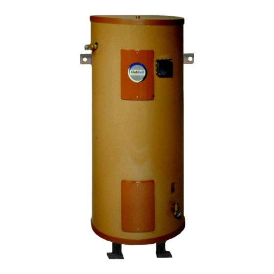
- Page 1 OPERATING AND MAINTENANCE MANUAL FOR MARINE ELECTRIC WATER HEATER ELECTRIC HEATER COMPANY BASE MODEL “ ME ”...
- Page 2 HUBBELL ELECTRIC HEATER COMPANY P.O. BOX 288 STRATFORD, CT 06615 PHONE: (203) 378-2659 FAX: (203) 378-3593 INTERNET: http://www.hubbellheaters.com/ -- IMPORTANT -- Always reference the full model number and serial number when calling the factory. WARNING / CAUTION 1. Tank is to be completely filled with water and all air is to be vented before energizing.
-
Page 3: Table Of Contents
SECTION TITLE PAGE No. GENERAL DESCRIPTION AND CONSTRUCTION INSTALLATION SCHEDULED MAINTENANCE AND OPERATION TROUBLESHOOTING SERVICING AND REPLACEMENT OF PARTS MISCELANEOUS CHARTS AND FORMULAS ABS TYPE APPROVAL PROGRAM... -
Page 4: General Description And Construction
SECTION I - GENERAL DESCRIPTION AND CONSTRUCTION GENERAL DESCRIPTION This book describes a packaged electric water heater, approved by ABS Americas (A Division of the American Bureau of Shipping) and the USCG (United States Coast Guard), which is a stationary, self contained unit and is designed and constructed specifically for marine applications on board a surface vessel. - Page 5 TEMPERATURE HIGH LIMIT SWITCH As a safety device, either a surface mounted high temperature cut-off switch with manual reset, factory set at 190° F, or an immersion high temperature cut-off switch with manual reset, factory set at 180° F, is provided. In the event of an over-temperature condition, the thermostat will disengage the power from the system.
-
Page 6: Installation
SECTION II – INSTALLATION WARNING / CAUTION DO NOT TURN ON THE ELECTRIC POWER SUPPLY to this equipment until heater is completely filled with water and all air has been released. If the heater is NOT filled with water when the power is turned on, the heating elements will burn out. For protection against excessive pressures and temperatures, local codes require the installation of a temperature-and-pressure (T&P) relief valve certified by a nationally recognized laboratory that maintains periodic inspection of production of listed equipment of... - Page 7 Mounting Dimensions Tank Overall Bolt Bulkhead Gallon Diameter Diameter Circle Mounting Capacity “A” “B” “C” Dimension “D” None None None 18 3/4 22 3/4 PIPING INSTALLATION NOTE: The most effective means for preventing deterioration from accelerated corrosion due to galvanic and stray current is the installation of dielectric fittings/unions. The installation of these fittings is the responsibility of the installing contractor.
-
Page 8: Scheduled Maintenance And Operation
FINAL CHECKS 1. Check all connections for tightness. 2. Ensure that all the above steps are completed 3. After the water is heated for the first time, monitor the water temperature as described in Section III, Quarterly Inspection. SECTION III - SCHEDULED MAINTENANCE AND OPERATION WARNING / CAUTION Before performing any maintenance procedure, make certain power supply is OFF and... -
Page 9: Troubleshooting
SECTION IV – TROUBLESHOOTING Symptom Probable Cause Corrective Action / Remedy No hot water Circuit breaker tripped at Reset circuit breaker. source. High limit switch tripped. Reset high limit switch. Loose wires. Tighten wires. Torque screws per torque chart included in Section VI. Heating element inoperable. -
Page 10: Vservicing And Replacement Of Parts
SECTION V - SERVICING & REPLACEMENT OF PARTS WARNING / CAUTION Before servicing or replacing any part make sure to turn the power supply switch to the OFF position. SURFACE TEMPERATURE HIGH LIMIT CUT-OFF 1. Disconnect power from unit. 2. Remove access cover. 3. - Page 11 Reset Switch 4. Disconnect the two (2) 14 gauge wires. Wires Capillary Tubes 5. Remove capillary tube and bulb from thermowell 6. Remove two (2) mounting screws. Mounting Screws 7. Remove control and install new high limit switch by performing above steps in reverse order.
- Page 12 Tank Flange Wires 7. Remove the 3/8-16 nuts. 8. Withdraw element assembly and remove gasket. Gasket Element Assembly Nuts 9. Install new gasket and insert new heating element. 10. Rewire element according to type of unit as shown below. 11. Fill tank and check around gasket for any leaks.
- Page 13 Single Element Operation 3 Ø Open Delta Wiring for Simultaneous Operation...
- Page 14 Interlocked for Non-Simultaneous Operation Non-Interlocked for Simultaneous Operation...
- Page 15 SURFACE MOUNTED THERMOSTAT 1. Disconnect power from unit. 2. Remove access cover and locate thermostat. 3. Disconnect the two (2) or three (3) 14 gauge wires and jumpers, as required. Control Wires 4. Remove two (2) mounting screws and disconnect from high limit cut-off, if required. Mounting Screws 5.
- Page 16 4. Disconnect the two (2) or three (3) 14 gauge wires, as required. Wires Capillary Tube 5. Remove capillary tube and bulb from thermowell. 6. Remove two (2) mounting screws. Mounting Screws 7. Replace thermostat using reverse procedure. (Note: Be sure to place capillary tube into slot in base prior to installing cover.)
- Page 17 RELIEF VALVE 1. Disconnect power from unit. 2. Shut off incoming water supply. 3. Lift test lever on relief valve to relieve pressure in tank. 4. Disconnect overflow piping. 5. Unscrew relief valve, remove assembly and replace with new one. 6.
-
Page 18: Miscelaneous Charts And Formulas
SECTION VI – MISCELLANEOUS CHARTS AND FORMULAS ELEMENT CHART Power (Watts) Element Immersion Resistance Element Part # 120V 208V 240V 277V 480V Length (Ohms) CH-FO-358 ---- 3500 ---- ---- ---- 11 3/8" 12.36 CH-FO-408 ---- 4000 ---- ---- ---- 11 3/8" 10.82 CH-FO-508 ----... - Page 19 TORQUE VALUES SILICON ALUMINUM 18-8 S/S BRASS 316 S/S MONEL BOLT SIZE BRONZE 2024-T4 IN.-LBS. IN.-LBS. IN.-LBS. IN.-LBS. IN.-LBS. IN.-LBS. 4-40 4-48 5-40 5-44 6-32 10.1 6-40 12.1 11.2 12.7 12.3 8-32 19.8 16.2 18.4 10.8 20.7 20.2 8-36 22.0 18.0 20.4 12.0...
-
Page 20: Abs Type Approval Program
SECTION VII – ABS TYPE APPROVAL PROGRAM... - Page 23 NOTES...
- Page 24 P.O. BOX 288 STRATFORD, CT 06615-0288 PHONE: (203) 378-2659 FAX: (203) 378-3593 INTERNET: http://www.hubbellheaters.com/...
Need help?
Do you have a question about the ME and is the answer not in the manual?
Questions and answers