Advertisement
Quick Links
INSTALLATION, SERVICING & OPERATING
"ULTRA" SERIES
OVERHEAD RADIANT PLAQUE HEATER
Ultra 7
Ultra 14
Ultra 21
Ultra 28
Ultra 42
Chapel Lane, Claydon, Ipswich
Tel: 01473 830551 Fax: 01473 832055
INSTRUCTIONS
MODELS
Ultra 7/3.5 - HI/LO
Ultra 14/7
Ultra 21/10.5- HI/LO
Ultra 28/14 - HI/LO
Ultra 42/21 - HI/LO
Gas Fired Products (UK) Ltd
Suffolk IP6 0JL, England
E-mail:
Info@spaceray.co.uk
www.spaceray.co.uk
- HI/LO
Advertisement

Subscribe to Our Youtube Channel
Related Manuals for Space-Ray Ultra 7


Summary of Contents for Space-Ray Ultra 7
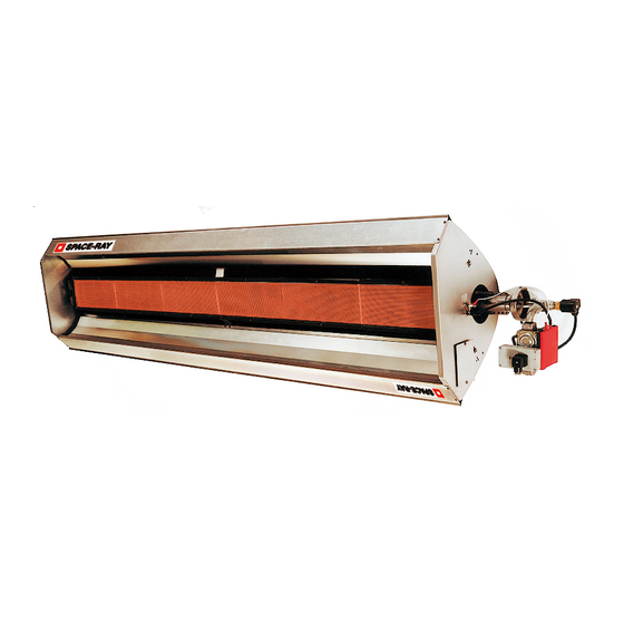
- Page 1 INSTALLATION, SERVICING & OPERATING INSTRUCTIONS "ULTRA" SERIES OVERHEAD RADIANT PLAQUE HEATER MODELS Ultra 7 Ultra 7/3.5 - HI/LO Ultra 14 Ultra 14/7 - HI/LO Ultra 21 Ultra 21/10.5- HI/LO Ultra 28 Ultra 28/14 - HI/LO Ultra 42 Ultra 42/21 - HI/LO...
-
Page 3: Table Of Contents
Ventilation 10 - 11 Assembly 11 - 12 Assembly Burner Assy to Basic Body Assy 11 - 12 Ultra 7, 14, 21, 28, 42 Ultra 7/3.5, 14/7, 21/10.5, 28/14, 42/21 Commissioning 13 - 14 Ignition Shut Down Checking Gas Pressure... -
Page 4: Technical Data
INSTALLATION , SERVICING & OPERATING INSTRUCTIONS 1.TECHNICAL DATA Table 1 MODEL Ultra 7-N Ultra 7-L Heat Input 6.66 kW (Hs) 6.0 kW (Hi) Appliance Type Appliance Cat. Adjusted for 2H G20 20 mbar 3P G31 50 mbar Setting Pressure 19.0 mbar 50.0 mbar... - Page 5 Table 4 MODEL Ultra 28-N Ultra 28-L Heat Input 26.64 kW (Hs) 24.0 kW (Hi) Appliance Type Appliance Cat. Adjusted for 2H G20 20 mbar 3P G31 50 mbar Setting Pressure 18.2 mbar 50.0 mbar Injector 2 x Ø2.55mm 2 x Ø1.75mm Orifice Plate Ø52 Ø52...
- Page 6 Table 6 MODEL Ultra 7/3.5 (HI/LO) - N Ultra 7/3.5 (HI/LO) - L Heat Input 6.66 kW/3.33 kW (Hs) 6.0 kW/3.0 kW (Hi) Appliance Type Appliance Cat. Adjusted for 2H G20 20 mbar 3P G31 50 mbar Setting Pressure 19.0 mbar 50.0 mbar...
- Page 7 Table 9 MODEL Ultra 28/14 (HI/LO) - N Ultra 28/14 (HI/LO) - L Heat Input 26.64 kW/13.33 kW (Hs) 24.0 kW/12.0 kW (Hi) Appliance Type Appliance Cat. Adjusted for 2H G20 20 mbar 3P G31 50 mbar Setting Pressure 18.2 mbar 50.0 mbar Injector 2 x Ø2.55mm...
-
Page 8: Un-Packing
UN-PACKING The appliance is supplied in a carton, broken down into two sub-assemblies, ie Basic Body Assembly and Burner Assembly. Where an Orifice Plate is required, it will be found, together with Qty 4- M5x6 set screws (for securing the Burner Assembly to the Basic Body Assembly) packed with the Burner Assembly. - Page 9 3.1.6 Minimum clearance from combustibles. Table 11 MODEL HORIZONTAL ABOVE BELOW SIDE FRONT BACK FRONT BACK Ultra 7 & 7/3.5 1000 1340 Ultra 14 & 14/7 1000 1000 2000 1000 2840 1255 Ultra 21 & 21/10.5 1365 1365 2480 1090...
- Page 10 HEATER 2 Fig. 3 3.3.3 Ultra 7/3.5 - 42/21 (Hi/Lo): Three core and earth PVC covered flexible supply cable (0.5mm - to National or Local standard specification) must be used, with connections made as shown in Fig. 4. Page 8 of 20...
- Page 11 ULTRA 7/3.5, 14/7, 21/10.5, 28/14 & 42/21 Hi/Lo SINGLE HEATER PER THEMOSTAT. BLACK GREEN / YELLOW BLUE BROWN THERMOSTAT 1 SWITCH THERMOSTAT 1 SWITCH THERMOSTAT 2 SWITCH THERMOSTAT 2 SWITCH HEATER 1 HEATER 2 MULTIPLE HEATERS PER THEMOSTAT. THERMOSTAT 2...
- Page 12 3.3.5 Internal Wiring Diagram L1 N ULTRA 7/3.5, 14/7, 21/10.5, 28/14 & 42/21 Hi/Lo 4 PIN SOCKET & PLUG BASE WIRING COLOUR CODES BK = BLACK BL = BLUE BR = BROWN G/Y = GREEN & YELLOW Y = YELLOW...
- Page 13 3.4.1.2 Ventilation by Mechanical Evacuation Ventilation by mechanical evacuation is sufficient if 10m /h of exhaust air per kW of operating heat input are ventilated out of the installation room. The air/products of combustion mixture must be evacuated above the radiant heaters using fan(s). It shall only be possible to operate the radiant heaters whilst the exhaust airflow is proven.
- Page 14 External fuse required - 3 amp. See section 3.3 for electrical supply requirements. Ultra 7/3.5, 14/7, 21/10.5, 28/14, 42/21 (HI/LO) 4.3.1 The appliance should be raised and suspended from chains or drop rods, or from brackets fixed to vertical surfaces which have been previously installed in accordance with Section 3.1.
-
Page 15: Commissioning
If the appliance has a thermostat fitted in the electrical supply circuit, ensure that it is set high enough to demand heat. Ultra HI/LO (e.g. Ultra 7/3.5): ensure that the second thermostat (T2 - see Fig. 4) is set high enough to call for heat also. - Page 16 (see Data Label, affixed to the appliance adjacent to the Controls. Category 2H: gas type G20 (natural): setting pressure - Ultra 7 & Ultra 7/3.5 - 19.0mbar Ultra 14 & Ultra 14/7 - 18.8mbar...
-
Page 17: Servicing
SERVICING It is essential that at least once a year, preferably before the heating season, the appliance is serviced by a qualified person. In exceptionally dirty conditions, such as may occur in a foundry, more frequent servicing may be desirable. IMPORTANT: 1. -
Page 18: Auxiliary Controls
6.5.2 To remove any dirt accumulated on the inside surface of the ceramic plaque, direct a supply of compressed air into the plenum chamber via the venturi. IMPORTANT: DO NOT DIRECT COMPRESSED AIR AT THE CERAMIC PLAQUE SURFACE AS IT MAY DAMAGE THE CERAMIC TILES. -
Page 19: Operating Instructions
Emitter Assembly (ceramic tiles) 7.6.1 In the unlikely event that a ceramic tile is damaged and requires replacement, contact Space-Ray at the address shown on the front cover of this manual. Replacement Parts List The following is a list of replacement parts which may be required during the life of the appliance. -
Page 20: Fault Finding Chart
Check Gas & Electricity supplies turned 'ON' 9. FAULT FINDING CHART Set Thermostat to 'MAX' Has Burner flame established Check 230V present at Ignition Control & circuit continuity 230V at Ignition Control & YES Check gas Supply pressure at circuit continuity correct control valve test point 'IN' Rectify electricity supply or Gas Supply pressure in... - Page 21 NOTES: Page 19 of 20...
- Page 22 09/03 GB IE 525S Page 20 of 20...
Need help?
Do you have a question about the Ultra 7 and is the answer not in the manual?
Questions and answers