Table of Contents
Advertisement
Quick Links
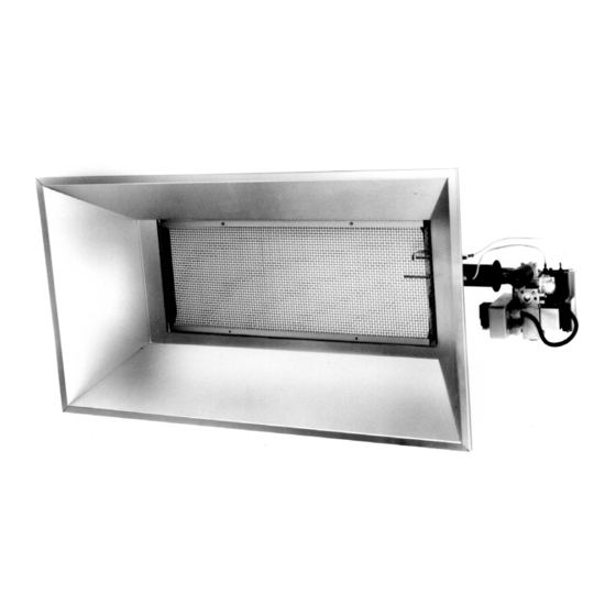
Overhead Radiant Plaque Heaters
INSTALLATION, SERVICING AND OPERATING
INSTRUCTIONS
SRP (DBI) SRP (PILOT) SERIES
MODELS:
SRP 08, SRP15, SRP 22, SRP30, SRP 30 Hi/Lo
Gas Fired Products (UK) Ltd
Chapel Lane, Claydon, Ipswich
Suffolk IP6 0JL, England
Tel: 01473 830551 Fax: 01473 832055
E-mail:
Info@spaceray.co.uk
www.spaceray.co.uk
Advertisement
Table of Contents

Related Manuals for Space-Ray SRP 08


Summary of Contents for Space-Ray SRP 08
- Page 1 Overhead Radiant Plaque Heaters INSTALLATION, SERVICING AND OPERATING INSTRUCTIONS SRP (DBI) SRP (PILOT) SERIES MODELS: SRP 08, SRP15, SRP 22, SRP30, SRP 30 Hi/Lo Gas Fired Products (UK) Ltd Chapel Lane, Claydon, Ipswich Suffolk IP6 0JL, England Tel: 01473 830551 Fax: 01473 832055 E-mail: Info@spaceray.co.uk...
-
Page 3: Table Of Contents
INSTALLATION, SERVICING AND OPERATING INSTRUCTIONS Before installation, check that the local distribution conditions, nature of gas and pressure, and adjustment of appliance are compatible. INDEX Section Title Page Technical Data 2 - 4 Un-Packing Installation 5 - 10 Suspension 5 - 6 Gas Supply 6 - 7 Electrical Supply... -
Page 4: Technical Data
INSTALLATION, SERVICING & OPERATING INSTRUCTIONS Technical Data Table 1 MODEL SRP08-N Heat Input 7.6kW (Hs) 6.84kW (Hi) Appliance Type Appliance Cat. Adjusted for 2H G20 20mbar Setting Pressure 12.0mbar Injector Ø2.2mm Pre-Injector None Electrical Supply 230v~50Hz 25W Fuse Externally Dimensions L = 0.645m W = 0.428m H= 0.325m Weight 6.0kg... - Page 5 Table 4 MODEL SRP30-N SRP30-L Heat Input 30.4kW (Hs) 27.36kW (Hi) 30.0kW (Hs) 27kW (Hi) Appliance Type Appliance Cat Adjusted for 2H G20 20mbar 3+ G30/31 29/37mbar Setting Pressure 12.0mbar None Injector 2 x Ø3.1mm 2 x Ø1.9mm Pre-Injector None None Electrical Supply 230V ~ 50Hz 25W...
- Page 6 Table 6 MODEL SRP08 (PILOT)-N Heat Input 7.6kW (Hs) 6.84kW (Hi) Appliance Type Appliance Cat Adjusted for 2H G20 20mbar Setting Pressure 12.0mbar Injector Ø2.2mm Pilot Injector TJ020 Dimensions L = 0.615m W = 0.428 H = 0.325m Weight 6.0kg Gas Connection Rc - ½...
-
Page 7: Un-Packing
UN-PACKING The appliance is supplied in a carton, assembled complete and ready for installation. Any optional equipment supplied is packed inside the carton also. INSTALLATION Not withstanding their limited scope, the appliance should be installed in accordance with the relevant provisions of any National Gas Safety (Installation and Use Regulations). -
Page 8: Gas Supply
3.1.6 Minimum clearance from combustibles. Above Above Front Front Back Back 45° max Below Below Above Side Side Fig. 2 MODEL HORIZONTAL ABOVE BELOW SIDE FRONT BACK FRONT BACK SRP08 610mm 610mm 865mm 205mm 915mm 1220mm 610mm SRP15 915mm 915mm 1830mm 305mm 915mm... -
Page 9: Electrical Supply
Three core and earth PVC covered flexible supply cable (0.5mm - to National or Local standard specification) must be used, with connections made as shown in Fig. 4. SRP 08, 15, 22 & 30 SINGLE HEATER PER THERMOSTAT GREEN/YELLOW BLUE... - Page 10 N.B. In the event of an electrical fault after installation of the appliance, preliminary system checks are required to be carried out, i.e. earth continuity, polarity and resistance to earth. 3.3.4 Internal Wiring Diagram (Honeywell Controls) SRP 08, 15, 22 & 30 WIRING COLOUR CODES BK = BLACK BL = BLUE BR = BROWN G/Y = GREEN &...
- Page 11 Hi/Lo OPERATION VENTURI CONTROL VALVE Fig. 6 3.3.5 Internal Wiring Diagram (S.I.T. Controls) SRP 08, 15, 22 & 30 S.I.T. (0.537.008) IGNITION CONTROL - 4262535 12 11 10 9 12 WAY 0.2 PITCH KK CONNECTOR 4262107 BL (HT) WIRING COLOUR CODES...
- Page 12 SRP 30 Hi/Lo S.I.T. (0.537.008) IGNITION CONTROL - 4262535 12 WAY 0.2 PITCH KK CONNECTOR 4262107 BL (HT) BY-PASS VALVE WIRING COLOUR CODES (SRP 30 Hi/Lo) BK = BLACK BL = BLUE BR = BROWN G/Y = GREEN & YELLOW GR = GREY 4 PIN BASE PLUG TERMINAL BLOCK...
-
Page 13: Ventilation
3.4.1.2 Ventilation by Mechanical Evacuation Ventilation by mechanical evacuation is sufficient if 10m /h of exhaust air peer kW of operating heat input ³ are ventilated out of the installation room. The air/products of combustion mixture must be evacuated above the radiant heaters using fan(s). It shall only be possible to operate the radiant heaters whilst the exhaust airflow is proven. -
Page 14: Direct Burner Spark Ignition-Srp30 Hi/Lo
SRP30 Hi/Lo (Direct Burner Spark Ignition) 4.2.1 The appliance should be raised and suspended from chains or drop rods, or from brackets fixed to vertical surfaces that have been previously installed in accordance with Section 3.1. - Suspension. 4.2.2 Connect the gas supply in accordance with Section 3.2. - Gas supply, of these Installation Instructions. 4.2.3 Using three core and earth flexible supply cable as specified in section 3.3.3, suitable for 230v ~ 50Hz 25W supply, connect the 4 pin electrical socket provided (fitted to junction box, attached to the Control valve) as... -
Page 15: Commissioning
Commissioning It is essential that all new pipework installations are purged and tested for sounding using a suitable leak detection fluid prior to attempting to ignite any appliance. This work should be carried out in accordance with National or Local Regulations. N.B. -
Page 16: Flame Supervision
5.1.3.1.2 Ignite the appliance burner by switching on the electrical supply to the appliance and check that the manometer reading is as stated below, for the gas type the appliance is adjusted for (see Data Label affixed to the appliance reflector, below the control valve). Category 2H: gas type G20 (natural): supply pressure 20mbar (nom) 17mbar (min) -
Page 17: Shut Down
5.2.1.3 Press slightly and turn the control knob counter clockwise to the PILOT position, depress the control knob and ignite the pilot by passing a lighted taper through the hole in the pilot housing assembly (venting of air may take place prior to flow of pilot gases). -
Page 18: Flame Supervision
5.2.3.2.2 Ignite the appliance burner from the pilot burner flame by pressing and turning the control valve operating knob counter clockwise to the 'ON' position. Check that the manometer reading is as stated below, for the gas type the appliances is adjusted for (see Data Label, affixed to the appliance reflector, below the control valve. SRP08/SRP15 Category 2H: gas type G20 (natural): setting pressure 12.0mbar... -
Page 19: Flame Sensor Probe
Flame Sensor Probe 6.2.1 Disconnect the grey flame sensor lead from the sensor probe by gently pulling the connector, using pliers. 6.2.2 Unscrew the two M4 screws, securing the sensor probe to the flue collar assembly and withdraw the probe. 6.2.3 Remove any foreign matter from the sensor rod and check the condition of the ceramic insulator. -
Page 20: Pilot Burner Frame (Standing Pilot Ignition)
6.7.4 The appliance may now be disconnected from the suspension means and carefully lowered to the ground. See section 7.15 for detailed instructions concerning replacement of the emitter assembly. 6.7.5 Carefully brush any foreign material from the back of the emitter (ceramic tile) assembly, using a soft brush. Clean the inside of the plenum body also. -
Page 21: Ignition Control
Ignition Control (Honeywell S4565P 2024) 7.3.1 Disconnect both the grey flame sensor lead and black HT ignition lead from the ignition control. 7.3.2 Unscrew the screw securing the red cover to the ignition control and remove the cover. 7.3.3 Unscrew the two screws securing the cable clamp to the ignition control and remove the cable clamp. 7.3.4 Disconnect the 10 way Molex electrical connector from the ignition control and gently pull the ignition control from the gas control valve. -
Page 22: Thermocouple (Pilot Ignition)
7.9.1 Disconnect the thermopile leads and any ON/OFF switch/room thermostat leads from the millivolt controller of the gas control valve (connections marked TH and TP - see Fig. 9). 7.9.2 Unscrew the thermocouple nut securing the thermocouple to the control valve and remove the thermocouple. 7.9.3 Disconnect the gas supply pipe from the control valve inlet port. -
Page 23: Emitter Assembly
7.14.4 When assembling a replacement reverberatory screen, ensure that it is positioned on the cross support, at the controls end to prevent shorting of the flame sensor. 7.15 Emitter Assembly 7.15.1 Having disconnected the electrical and gas supplies from the appliance and lowered the appliance to the ground, (see sections 6.7.3 and 6.7.4) place the appliance on a work bench and carry out the following instructions. -
Page 24: Standing Pilot Ignition Models
8.1.5 Failure to ignite will result in the ignition controller going to "Lockout" condition. 8.1.6 If 'Lockout' occurs, switch off the electrical supply to the appliance, wait for 10 seconds before switching on the electrical supply to the appliance to repeat the ignition sequence. 8.1.7 If the appliance fails to ignite after a second sequence, switch off the electricity supply to the appliance and call the service engineer. - Page 25 NOTES: Page 23 of 24...
- Page 26 07/05 GB IE (ES PT) 484S Page 24 of 24...
Need help?
Do you have a question about the SRP 08 and is the answer not in the manual?
Questions and answers