Flavel Kenilworth HE Installation, Maintenance & User Instructions
Hide thumbs
Also See for Kenilworth HE:
- Installation, maintenance & user instructions (64 pages) ,
- Installation, maintenance & user instructions (90 pages)
Table of Contents
Advertisement
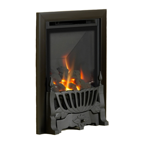
Kenilworth HE,
Linear HE &
Diamond HE
INSET LIVE FUEL EFFECT GAS FIRE
Installation, Maintenance & User Instructions
Hand these instructions to the user
Model No's FHKC**MN2, FHKC**SN2, FHKC**RN2, FHLC**MN2,
FHLP**MN2, FHDC**RN2 & FHDP**RN2 are only for use on Natural
Gas (G20) at a supply pressure of 20 mbar in G.B. / I.E.
** denotes trim and fret variant
Advertisement
Table of Contents

Related Manuals for Flavel Kenilworth HE


Summary of Contents for Flavel Kenilworth HE
- Page 1 Kenilworth HE, Linear HE & Diamond HE INSET LIVE FUEL EFFECT GAS FIRE Installation, Maintenance & User Instructions Hand these instructions to the user Model No’s FHKC**MN2, FHKC**SN2, FHKC**RN2, FHLC**MN2, FHLP**MN2, FHDC**RN2 & FHDP**RN2 are only for use on Natural Gas (G20) at a supply pressure of 20 mbar in G.B.
-
Page 2: Table Of Contents
CONTENTS Section 1 Information and Requirements PAGE Appliance Information Conditions of Installation Flue and chimney suitability Fireplace / surround suitability Shelf position Chimney inspection Fire place opening / catchment space Fitting to Metal Flue Boxes Fitting to Pre-Cast Flues Spillage Monitoring System 1.10 Wall / Hearth Mounting Section 2... -
Page 3: Information And Requirements
SECTION 1 INFORMATION AND REQUIREMENTS APPLIANCE INFORMATION Model FHKC**M/S/RN2 (Kenilworth) FHLC/P**MN2 (Linear) FHDC/P**RN2 (Diamond) Gas Type Main injectors (2 off) Size 130 Pilot Type Copreci 21100 / 141 (MC) Copreci 21100 / 162 (SC & RC) Max. Gross Heat Input : 4.5 kW Min. -
Page 4: Conditions Of Installation
INSTALLATION REQUIREMENTS CONDITIONS OF INSTALLATION It is the law that all gas appliances are installed only by a Registered Installer, in accordance with these installation instructions and the Gas Safety (Installation and Use) Regulations 1998 as amended. Failure to install appliances correctly could lead to prosecution. -
Page 5: Fireplace / Surround Suitability
FIREPLACE / SURROUND SUITABILITY The fire must only be installed on a hearth it must not be installed directly onto carpet or other combustible floor materials. The fire is suitable for fitting to non-combustible fire place surrounds and proprietary fire place surrounds with a temperature rating of at least 150 o c. -
Page 6: Fire Place Opening / Catchment Space
Check the chimney pot / terminal and general condition of the brickwork or masonry. If the chimney or flue is in poor condition or if there is no up-draught do not proceed with the installation. If there is a history of down-draught conditions with the chimney / flue, a tested and certificated flue terminal or cowl suitable for the relevant flue type should be considered. -
Page 7: Fitting To Metal Flue Boxes
Table A - Installation Depth Requirements for a Flavel Kenilworth HE / Linear HE / Diamond HE being installed into a brick built chimney, requiring 12.0 litres of debris collection volume (fig. 2) When installing this product into a brick built chimney, there must be a minimum depth available of 200mm available for the collection of debris behind the firebox when installed. -
Page 8: Fitting To Pre-Cast Flues
FITTING TO PRE-CAST FLUES When installing this appliance into pre-cast flues, always ensure that the spigot restrictor baffle has been removed. To install the fire box in to pre-cast flue starter blocks, there must be at least 180mm from the mounting face of the fire to the rear of the pre-cast flue starter block to allow sufficient space for debris collection. -
Page 9: Wall / Hearth Mounting
1.10 WALL / HEARTH MOUNTING This appliance must be fitted on a flat, non-combustible base of minimum thickness 12mm. In addition, a non-combustible hearth or physical barrier should be provided in front of the fire. With “hole in the wall” type installations, where it may be desirable not to fit a hearth panel or physical barrier, the product may be installed in accordance with Document J of the building regulations so that every part of the flame or incandescent material is at least 225mm above the floor level. -
Page 10: Installation Of Fire
SECTION 2 INSTALLATION OF FIRE UNPACKING THE FIRE Carefully lift the fire out of the carton. Remove the loose item packaging carefully from the front of the appliance. Check the contents as listed :- Packing Check List 1off Fire box / burner assembly 1off Boxed ceramic base, front ceramic rail and 7 coals or 13 pebbles (4 off “FR”pebbles 7 off “L”... - Page 11 For all models proceed as follows :- Remove the top glass retaining cover from the product. It is secured via the two screws as indicated. See fig. 6 below. Fig. 6 2 off securing screws Remove the left and right hand side glass securing brackets from the product.
- Page 12 Lift the glass panel forwards and clear from the firebox, taking care not to damage the glass panel. See fig. 8 below Fig. 8 Remove the burner heat shield, which is retained by 2 off screws as shown below in fig. 9 Fig.
- Page 13 For all Manual Control models proceed as follows :- Remove the two off screws from the left and right hand burner mounting brackets, plus the two screws from the base of the control panel as shown below in Fig. 10, this will allow removal of the complete burner unit from the firebox.
- Page 14 For all Slide Control models proceed as follows :- Remove the burner. To allow burner removal, the control lever operating cable must be removed. The control lever operating cable can be seen running across the base of the fire, below the burner. To release the cable, unscrew the cable securing screw located in the centre of the aluminium operating arm and pull the cable out from its fixing hole.
- Page 15 Continue for all models as follows :- Whilst the fire box is still in position, decide which side the gas supply is to enter the fire from. If concealed pipe work is required plan the pipe run to enter the fire box through one of the openings in the sides or rear of the fire box below the fuelbed support panel and connect to the isolating / inlet elbow.
- Page 16 IMPORTANT : Sealing of the Gas Unused Gas Pipe Inlet Apertures In line with current regulations, it is imperative that the gas supply inlet aper- tures that are not utilised during the installation are sealed with the foil tape as supplied. Failure to seal these inlet apertures could lead to flame reversal, which in turn will damage the burner and control systems of the product.
- Page 17 The preferred method of fixing which is suitable for almost all situations is the cable fixing method which is described in the following section in detail. To fit using the preferred cable method proceed as follows- Mark out and drill 4 off No 14 (6mm) holes in the back face of the fire opening in the positions shown below in fig.
- Page 18 Fig. 18 Evenly tighten the tensioning nuts to tension both cables and pull the fire snugly against the wall. Do not overtighten, it is only necessary to pull the seal up against the sealing face of the wall, it does not need to be compressed.
-
Page 19: Gas Tightness And Inlet Pressure (Mc Models)
The other firebox fixing method is as follows :- In installations where the cable method is not suitable (e.g. loose masonary in rear of fire opening) the firebox can be secured to the fire surround using four screws and wall plugs provided. Below (fig. 19) is a diagram to indicate the hole centre positions available on the firebox to facilitate the screw fixing to the fireplace / surround. -
Page 20: Gas Tightness And Inlet Pressure (Sc Models)
GAS TIGHTNESS AND INLET PRESSURE (SLIDE CONTROL MODELS). Remove the pressure test point screw from the pressure test point and fit a manometer. Turn on the main gas supply and carry out a gas tightness test. Depress the control lever to the position marked pilot. Hold down the control lever for a few seconds to purge the pipe work. -
Page 21: Assembling Fuel Bed And Commissioning
SECTION 3 ASSEMBLING FUEL BED AND COMMISSIONING ASSEMBLING THE CERAMICS AND FUEL BED - COAL MODELS Place the ribbed ceramic fuelbed base on top of the fuelbed support and pull fully forwards to the burner. Make sure that the fuelbed base is located centrally in the fire box. - Page 22 Position the front ceramic coal support onto the burner support as shown below in Fig. 22 Fig. 22 Positioning of front ceramic coal support onto burner support Fit the front row left hand coal as shown below in Fig. 23 Fig.
- Page 23 Fit the front row left hand side central coal as shown below in Fig. 24. Fig. 24 Fit the front row right hand side central coal as shown below in Fig. 25. Fig. 25...
- Page 24 Fit the front row right hand coal as shown below in Fig. 26 Fig. 26 Fit the rear row of 3 coals as shown below in Fig. 27 Fig. 27 The exact position and fit of the coals may be very finely adjusted to give the most pleasing and random appearance.
- Page 25 Warning : Use only the coals supplied with the fire. When replacing the coals remove the old coals and discard them. Fit a complete set of coals of the correct type. Do not fit additional coals or any coals other than a genuine replacement set. To ensure that the release of fibres from these R.C.F (Refractory Ceramic Fibre) articles is kept to a minimum, during installation and servicing we recommend that you use a HEPA filtered vacuum to remove any dust...
-
Page 26: 3.1 Assembling The Ceramics And Fuel Bed - Pebble Models
3.1 ASSEMBLING THE CERAMICS AND FUEL BED - PEBBLE MODELS Place the ribbed ceramic fuelbed base on top of the fuelbed support and pull fully forwards to the burner. Make sure that the fuelbed base is located centrally in the fire box. Ensure that the fuelbed base fit fully down onto the fuel bed support and is not lodged on the burner. - Page 27 Position the front ceramic pebble support onto the burner support as shown below in Fig. 30 Fig. 30 Positioning of front ceramic pebble support onto burner support Fit four of the specially shaped pebbles as shown below in fig 31. Ensure that the cut-out in the rear face of the pebbles is positioned as indicated.
- Page 28 Select three of the large pebbles and position on the three central ribs in the fuelbed as indicated in Fig. 32 below. Fig. 32 3 off large pebbles Select the two small pebbles and arrange along the second row of the fuelbed.
- Page 29 Select the four remaining large pebbles and position as shown along the rear of the fuel-bed base in fig. 34 below. Fig. 34 4 off large coals Do a final check that the pebbles are layed out as shown below in Fig.
-
Page 30: Lighting The Appliance (Manual Control Model)
Warning : Use only the pebbles supplied with the fire. When replacing the pebbles remove the old pebbles and discard them. Fit a complete set of pebbles of the correct type. Do not fit additional pebbles or any pebbles other than a genuine replacement set. To ensure that the release of fibres from these R.C.F (Refractory Ceramic Fibre) articles is kept to a minimum, during installation and servicing we recommend that you use a HEPA filtered vacuum to remove any dust... -
Page 31: Lighting The Appliance (Slide Control Model)
Slightly depress the control knob and turn to the pilot position, the main burner will go out but the pilot will remain lit. Slightly depress the control knob and turn to the off position, the pilot will now be extinguished. WARNING : If the fire goes out for any reason or is turned off and it isnecessary to re-light the fire it is important to allow the fire to cool for 3 minutes before attempting to re-light it. -
Page 32: Connecting The Battery Pack (Remote Control Model)
CONNECTING THE BATTERY PACK (Remote Control Models) To prevent un-necessary battery drain, the battery pack that is used to provide the remote control function for this product is disconnected at the factory. Prior to attempting to light the product, can the installer please ensure that the battery pack is re-connected as shown in section b), &... -
Page 33: Fixing The Infra-Red Eye
FIXING THE INFRARED SENSOR IN POSITION (Remote Control Models) Due to the large amount of different fascia’s that can be supplied with these fires, the infrared sensor is supplied from the factory attached to a self adhesive pad. This pad can therefore be attached to the hearth or fascia (Diamond HE models) in a position to suit the form of the fret or contemporary trim assembly that is chosen with the product. -
Page 34: Lighting The Appliance (Remote Control Model)
LIGHTING THE APPLIANCE (Remote Control Models) The Remote control handset generates an infrared signal, which will be received by the sensor situated at the front right of your fire, behind the black controls cover. This infrared signal requires direct line of sight from the handset to the sensor on the fire to ensure good operation. -
Page 35: Fitting The Trim / Fret (Kalahari Models)
FITTING THE TRIMS & FRETS (Kenilworth Models) Fit the outer trim assembly to the firebox with the magnets provided. Remove the fret & ashpan cover from the packaging. Place fret up to the front radiused burner heat shield Place ashpan cover under fret assembly and centralise. NOTE : Some models in this range are not supplied with a fret from the factory, therefore please consult your local retailer for fitting... -
Page 36: Checking For Clearance Of Combustion Products
3.11 CHECKING FOR CLEARANCE OF COMBUSTION PRODUCTS Close all doors and windows in the room. Light the fire and allow to run for approximately 5 minutes on high position. After approximately 5 minutes hold a smoke match just inside and below the centre of the lower front edge of the top of the fire as shown at the bottom of the page in Fig. -
Page 37: Section 4
MAINTENANCE Servicing Notes Servicing should be carried out annually by a competent person such as a registered engineer. This is a condition of the Flavel extended guarantee schemes. The service should include changing the oxypilot as a condition of the guarantee and visually checking the chimney and fire opening for accumulations of debris and a smoke test to check for a positive up-draught in the chimney. -
Page 38: Removal Of The Piezo Igniter (Manual Control Models)
Removing the Piezo Igniter (MC models) 4.2.1 Remove the burner assembly as in section 4.1 4.2.2 Disconnect the ignition lead from the piezo and unscrew the retaining nut on the rear of the control panel. Withdraw the piezo from the front of the control panel. Reassemble in reverse order and carry out a gas tightness test. - Page 39 4.4.4 Re-assemble in reverse order and carry out a gas tightness test. Refit the burner heat shield then refit the coals / pebbles referring to section 3 for the correct coal layout. Refit the glass panel and glass panel retaining trims. The fender and ash pan cover or fascia can now be re-positioned.
-
Page 40: Removal Of The Burner Assembly (Slide Control Models)
Slide Control Fires - For Diagrams refer to section 2 Removal of the burner assembly (SC models) 4.5.1 Prepare the work area (lay down dust sheets etc,) 4.5.2 Remove the trim. Lift the fender and ash pan cover out of the way and put them in a safe location. -
Page 41: Replacing The Battery (Slide Control Models)
that the left hand micro-switch operates the igniter and that the control valve spindle is fully depressed. Move the control lever upwards to the “off” position and check that the right hand (cut-off) micro-switch operates. Check that the control lever operates smoothly and safely. Refit the burner heat shield then refit the coals / pebbles referring to section 3 for the correct coal / pebble layout. -
Page 42: Replacing The Control Cable (Slide Control Models)
correct coal layout. 4.8.4 Refit the glass panel and glass panel retaining (Cont.) trims. The fender and ash pan cover or fascia can now be re-positioned. Replacing the Control Cable (SC models) 4.9.1 The control lever operating cable Fig. 41 can be seen running across the base of the fire, below the burner. -
Page 43: Removal Of The Burner Assembly (Remote Control Models)
4.9.6 It is now necessary to correctly tension the operating cable. To do this, first set the control lever to the horizontal (central position), this is the position which creates maximum tension in the operating cable. Pull the free end of the operating cable through the operating arm until it is finger tight and secure with screw into operating arm (do not over tighten). -
Page 44: Removing The Oxy-Pilot Assembly (Remote Control Models)
5.2.2 Remove the burner assembly as described in section 5.1. 5.2.3 Disconnect pilot, main and injector pipes and disconnect the wiring loom thermocouple and ignition wire, the valve can then be removed. Re-assemble in reverse order, refit the burner heat shield then refit the coals referring to section 3 for the correct coal layout. - Page 45 PARTS SHORTLIST Replacement of parts must be carried out by a competent person such as a registered gas installer. The part numbers of the replaceable parts are as follows, these are available from your local stockist, whose details may be found on the BFM Europe website, address as per rear page.
- Page 46 SECTION SIX - USER INSTRUCTIONS 6.1 INSTALLATION INFORMATION CONDITIONS OF INSTALLATION It is the law that all gas appliances are installed only by a competent (e.g. Registered) Installer, in accordance with the installation instructions and the Gas Safety (Installation and Use) Regulations 1998. Failure to install appliances correctly could lead to prosecution.
- Page 47 ABOUT YOUR NEW KENILWORTH / LINEAR / DIAMOND HE (High Efficiency) The Flavel High Efficiency coal / pebble effect gas fire incorporates a unique and highly developed fuel bed which gives the realism of a loose coal / pebble layout combined with realistic flames and glow.
-
Page 48: Operating The Fire (Mc Models)
6.2.1 OPERATING THE FIRE (MANUAL CONTROL MODELS) The controls are located behind the ashpan cover which is situated behind the Ashpan / Fender. The controls, comprise a control valve to adjust the gas flow and a push button piezo igniter. There is also a flame adjuster which slides from left to right on coal models only. -
Page 49: Operating The Fire (Rc Models)
6.2.2 OPERATING THE FIRE (REMOTE CONTROL MODELS) The Remote control handset generates an infrared signal, which will be received by the sensor situated at the front right of your fire, behind the black controls cover. This infrared signal requires direct line of sight from the handset to the sensor on the fire to ensure good operation. -
Page 50: Remote Handset Malfunction
6.2.3 TURNING THE PRODUCT OFF IN THE UNLIKELY EVENT OF A REMOTE HANDSET MALFUNCTION. In the unlikely event of the remote control handset malfunctioning (or if lost or broken) after the appliance has been turned on, the fire can be turned off via the emergency shut off switch on the control panel. -
Page 51: Operating The Fire (Sc Models)
6.2.4 OPERATING THE FIRE (SLIDE CONTROL MODELS) The controls comprise a control lever, to turn the fire on and off and adjust the gas rate. The control lever is located at the top right hand side of the fire. Depressing the control lever fully operates the igniter and lights the pilot flame and ignition rate gas. -
Page 52: Re-Assembling The Ceramics And Fuel Bed (Coal Models)
RE-ASSEMBLING THE CERAMICS AND FUEL BED - COAL MODELS NOTE : The position of the fuel-bed components are critical to the performance of the product. Therefore please ensure that the fuel-bed components are positioned as described in the following section prior to requesting a service call due to soot build up, poor flame pattern etc. - Page 53 Position the front ceramic coal support onto the burner support as shown below in Fig. 5 Fig. 5 Positioning of front ceramic coal support onto burner support Fit the front row left hand coal as shown below in Fig. 6 Fig.
- Page 54 Fit the front row left hand side central coal as shown below in Fig. 7. Fig. 7 Fit the front row right hand side central coal as shown below in Fig. 8 Fig. 8...
- Page 55 Fit the front row right hand coal as shown below in Fig. 9 Fig. 9 Fit the rear row of 3 coals as shown below in Fig. 10 Fig. 10 The exact position and fit of the coals may be very finely adjusted to give the most pleasing and random appearance.
- Page 56 Warning : Use only the coals supplied with the fire. When replacing the coals remove the old coals and discard them. Fit a complete set of coals of the correct type. Do not fit additional coals or any coals other than a genuine replacement set. To ensure that the release of fibres from these R.C.F (Refractory Ceramic Fibre) articles is kept to a minimum, during installation and servicing we recommend that you use a HEPA filtered vacuum to remove any dust...
-
Page 57: Re-Assembling The Ceramics And Fuel Bed (Pebble Models)
RE-ASSEMBLING THE CERAMICS AND FUEL BED - PEBBLE MODELS Remove the glass panel and retaining trims as detailed on page 11 & 12. Place the ribbed ceramic fuelbed base on top of the fuelbed support and pull fully forwards to the burner. Make sure that the fuelbed base is located centrally in the fire box. - Page 58 Position the front ceramic pebble support onto the burner support as shown below in Fig. 13 Fig. 13 Positioning of front ceramic pebble support onto burner support Fit four of the specially shaped pebbles as shown below in fig. 14 Ensure that the cut-out in the rear face of the pebbles is positioned as indicated.
- Page 59 Select three of the large pebbles and position on the three central ribs in the fuelbed as indicated in Fig. 15 below. Fig. 15 3 off large pebbles Select the two small pebbles and arrange along the second row of the fuelbed.
- Page 60 Select the four remaining large pebbles and position as shown along the rear of the fuel-bed base in fig. 17 below. Fig. 17 4 off large coals Do a final check that the pebbles are layed out as shown below in Fig.
-
Page 61: Cleaning The Fire
Warning : Use only the pebbles supplied with the fire. When replacing the pebbles remove the old pebbles and discard them. Fit a complete set of pebbles of the correct type. Do not fit additional pebbles or any pebbles other than a genuine replacement set. To ensure that the release of fibres from these R.C.F (Refractory Ceramic Fibre) articles is kept to a minimum, during installation and servicing we recommend that you use a HEPA filtered vacuum to remove any dust... -
Page 62: Removal & Re-Fitting The Trim / Fret / Fascia
To clean the glass panel, please remove it from the product as described in pages 10-11. Use a clean damp cloth and ceramic glass cleaner to remove any stains or deposits frm the glass panel. Do not using scouring pads as this may scratch the surface finish of the glass panel. - Page 63 Due to our policy of continual improvement and development the exact accuracy of illustrations and descriptions contained in this book cannot be guaranteed Part No. B-124970 Issue 4 BFM Europe Ltd. Trentham Lakes Stoke-on-Trent Staffordshire ST4 4TJ www.bfm-europe.com Telephone - General Enquiries : (01782) 339000 Telephone - Service : (0844) 7700169 or (01782) 339008...
Need help?
Do you have a question about the Kenilworth HE and is the answer not in the manual?
Questions and answers