Table of Contents
Advertisement
Quick Links
Download this manual
See also:
Owner's Manual
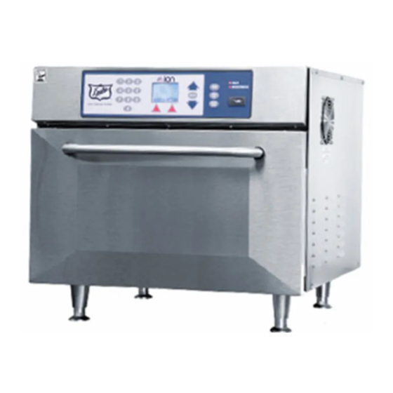
SPEED OVEN
MODEL
RCO
Please read this manual completely before attempting
This document is prepared for trained Duke service technicians. It is not to be used by anyone not
properly qualified to perform these procedures.
This Service Manual is not all encompassing. If you have not been trained on servicing this product,
be sure to read the manual completely before attempting servicing. Be sure all necessary tools,
test equipment, and skills are available. Those procedures for which you do not have the proper
skills and test equipment must be performed only by a qualified Duke trained service technician.
This manual is Copyright © 2011 Duke Manufacturing Co. All rights reserved.
Reproduction without written permission is prohibited. Duke is a registered
to install, operate or service this equipment
trademark of the Duke Manufacturing Co.
Duke Manufacturing Co.
2305 N. Broadway
St. Louis, MO 63102
Phone: 314-231-1130
Toll Free: 1-800-735-3853
Fax: 314-231-5074
www.dukemfg.com
Service Manual
1
2
3
TIME
4
5
6
TEMP
SELECT
FAN
7
8
9
MICRO
WAVE
10
HEAT
MICROWAVE
P/N 168939B
Advertisement
Table of Contents

Related Manuals for Duke RCO


Summary of Contents for Duke RCO
- Page 1 Please read this manual completely before attempting to install, operate or service this equipment This document is prepared for trained Duke service technicians. It is not to be used by anyone not properly qualified to perform these procedures. This Service Manual is not all encompassing. If you have not been trained on servicing this product, be sure to read the manual completely before attempting servicing.
-
Page 2: Important Warning And Safety Information
Service Manual for RCO Speed Oven IMPORTANT WARNING AND SAFETY INFORMATION THIS MANUAL HAS BEEN PREPARED FOR PERSONNEL QUALIFIED TO INSTALL ELECTRICAL EQUIPMENT, WHO SHOULD PERFORM THE INITIAL FIELD STARTUP AND ADJUSTMENTS OF THE EQUIPMENT COVERED BY THIS MANUAL. READ THIS MANUAL THOROUGHLY BEFORE OPERATING, INSTALLING OR PERFORMING MAINTENANCE ON THE EQUIPMENT. - Page 3 Service Manual for RCO Speed Oven FDA CODE OF FEDERAL REGULATIONS PRECAUTIONS TO BE OBSERVED BEFORE AND DURING SERVICING: TO AVOID POSSIBLE EXPOSURE TO EXCESSIVE MICROWAVE ENERGY: A. Do not operate or allow the oven to be operated with the door open.
-
Page 4: Table Of Contents
Service Manual for RCO Speed Oven TABLE OF CONTENTS INSTALLATION .........................6 UNPACKING.......................6 RADIO INTERFERENCE ...................6 OVEN PLACEMENT....................6 ELECTRICAL REQUIREMENTS ................6 GROUNDING INSTRUCTIONS .................6 TOOLS ........................7 SPECIFICATIONS ......................7 REMOVAL AND REPLACEMENT OF COMPONENTS ............8 Electrical LOCKOUT/TAGOUT Procedure ..............8 COVERS AND PANELS .....................8 Top Panel ......................8... - Page 5 Service Manual for RCO Speed Oven SYSTEM AND COMPONENT TESTING ................30 GENERAL SYSTEM TEST ..................30 Introduction .......................30 Oven Operating Statistics ..................30 Screen Displays ....................30 FAN TEST .........................31 CLEAR COUNTS .....................32 MICROWAVE LEAKAGE TEST ................32 COMPONENT TESTING ....................33 DISCHARGING THE HIGH VOLTAGE SYSTEM .............33 Function ......................33...
-
Page 6: Installation
OVEN PLACEMENT • The fuse used in this oven is Ferraz Shawmut OTM30 Fuse (Duke PN: 168120, 250 VAC, 30 A). • Do not install the oven next to or above source of heat, such as pizza oven or deep fat fryer. -
Page 7: Tools
Service Manual for RCO Speed Oven SPECIFICATIONS • The plug must be connected to a properly installed and grounded outlet. MODEL RCO (SINGLE PHASE – 208 – 240VAC 60Hz) • DO NOT change the unit’s cord. If the cord is too Input Power short an additional grounded outlet must be installed. Operating Voltage 208VAC to 240VAC, 60Hz • This oven must be connected to a separate circuit (Plug & Play) -
Page 8: Removal And Replacement Of Components
Service Manual for RCO Speed Oven REMOVAL AND REPLACEMENT OF COMPONENTS ELECTRICAL LOCKOUT/TAGOUT Top Panel PROCEDURE Before performing any service that involves electrical connection or disconnection Before performing any service that and/or exposure to electrical components, involves electrical connection or disconnection... -
Page 9: Rear Heater Cover
Service Manual for RCO Speed Oven The oven is equipped with two circulating fans mounted Removing the Louvered Rear Service Panel provides on the rear panel. An exhaust vent cover is mounted access to the High Voltage components. over each fan. These must be removed to gain access 1. -
Page 10: Exhaust Fan Replacement
Service Manual for RCO Speed Oven Exhaust Fan Replacement cooling for the electrical compartment. If not operating, the line fuse should be checked. Inspect all wiring 1. Remove the unit from its power source and follow between the fuse holder and the fan. Test the motor the proper Lockout/Tagout procedures. -
Page 11: Right Side Cooling Fan
Service Manual for RCO Speed Oven 8. Reverse this procedure to install a new Tangential 4. Remove the screws and nuts that secure the Blower assembly. Cooling Fan to the right side panel. Retain for use later. 9. Restore the unit to service and check for proper operation. -
Page 12: Monitor Relay
Service Manual for RCO Speed Oven 1. Remove the unit from its power source and follow magnetron system, or a combination of failures of the the proper Lockout/Tagout procedures. controller PCB, the Primary Door Switch, and the Secondary Door Switch are sources of Monitor circuit activation and 2. -
Page 13: Line Fuse
Service Manual for RCO Speed Oven LINE FUSE Before performing any service that Voltage involves electrical connection or disconnection Relay and/or exposure to electrical components, always follow the Electrical LOCKOUT/TAGOUT Procedure. Disconnect all circuits. Failure to comply can cause property damage, injury or death. -
Page 14: Control Box Assembly
Service Manual for RCO Speed Oven 3. Remove the fuse. Mounting 4. Perform a continuity test on the fuse. Screws 5. Replace the faulty fuse. 6. Restore the unit to its power source. 7. Ensure the unit is operating correctly. -
Page 15: Signal Transformer
Service Manual for RCO Speed Oven 5. Adjust the controller forward and backwards so that the trailing edge of the EMI shield contacts the back edge of the door. Signal Transformer Controller Controller Screw Shield Location of Signal Transformer Door... -
Page 16: Thermal Cutouts
Service Manual for RCO Speed Oven and panels. Monitor Switch 9. Restore power to the unit. 10. Perform a Microwave Leakage Test (as described Primary on page 32) to validate proper functionality. Interlock Switch THERMAL CUTOUTS Before performing any service that... -
Page 17: Heating Elements
Service Manual for RCO Speed Oven Thermal Cutout Replacement Testing Procedures 1. Remove the unit from its power source and follow Disconnect the wires from the Heating Elements. Test the proper Lockout/Tagout procedures. both elements using an Ohm meter. Each element should read from 18.14 to 21.01Ω. -
Page 18: Door Replacement
Service Manual for RCO Speed Oven 8. Remove the defective Heating Element. CAUTION: If the oven has been in use, the oven door may be hot. Allow door and oven cavity to cool before beginning this procedure. Heating Elements Arrestor... -
Page 19: Inverter
Service Manual for RCO Speed Oven 3. Lift and pull the door gently out of the hinge receiver 1. Remove the unit from its power source and follow brackets. Be careful not to bend the brackets. the proper Lockout/Tagout procedures. -
Page 20: Magnetron Cooling Fan
Service Manual for RCO Speed Oven 10. Restore the unit to its power source and ensure FAILURE TO INSTALL THE that it is operating correctly. BLOWER MOTORS PROPERLY WILL CAUSE THE OVEN TO OVERHEAT AND BECOME A FIRE HAZARD. MAGNETRON COOLING FAN 1. -
Page 21: Magnetron Thermal Switches
Service Manual for RCO Speed Oven Operational Testing housings may be hot. The Magnetron Cooling Fan operates constantly when the oven is connected to its power source. It provides cooling for both the Magnetrons and the High Voltage components. If not operating, the line fuse should be checked. -
Page 22: Magnetron
Service Manual for RCO Speed Oven Magnetrons Magnetron Location Thermal Switch Connection 5. Remove the faulty switch. Operational Testing 6. Install the replacement Thermal Switch. The right and left Mag circuits use identical components and wiring. Each Mag circuit has a dedicated 2.4KV 7. -
Page 23: High Voltage (Hv) Transformers
Service Manual for RCO Speed Oven has not been discharged. Magnetron 6. Tag and disconnect both Magnetrons and Magnetron Thermal Switches wiring. 7. Remove the Magnetron mounting nuts and the defective Magnetron. Make note of the Magnetron Chassis GND orientation before removing it. - Page 24 Service Manual for RCO Speed Oven rear of the unit behind the Magnetron Blower Assembly. Tap Relay NO = 208,††NC = 240 24Vdc COIL – Secondary Interlock Sw. Left Primary Interlock Sw. 30A†Fuse Monitor Bottom Right Relay High Voltage Monitor...
-
Page 25: High Voltage (Hv) Capacitors
Service Manual for RCO Speed Oven Always make sure a load is in the oven cavity before activating the microwave circuit. 17. Remove the unit from its power source and reattach all panels and covers. 18. Restore power to the unit. - Page 26 Service Manual for RCO Speed Oven The primaries of the Mag transformers have 208V or HV Capacitor Replacement 240V taps auto-selected by the controller PCB, based 1. Remove the unit from its power source and follow on sensed line supply voltage to the oven through the the proper Lockout/Tagout procedures.
-
Page 27: High Voltage (Hv) Diodes
Service Manual for RCO Speed Oven HIGH VOLTAGE (HV) DIODES The Monitor circuit detects failures in the Mag circuits from the output of the Mag SSR to the Monitor Door Switch to the Monitor Relay coil. The Monitor circuit Before performing any service that... -
Page 28: Waveguides
Service Manual for RCO Speed Oven 5. Tag and disconnect the Magnetron and Magnetron retains a 2.5kV DC charge after the oven has been disconnected from its power source. Thermal Switch wiring. The capacitor must be properly discharged 6. Remove the HV assembly. - Page 29 Service Manual for RCO Speed Oven 10. Use a slender tool to pry the Waveguide Mounting Waveguide Brackets away from the Waveguide, remove the Mounting Bracket Brackets and discard them. Magnetron on Left Side Removed Waveguide Removed 7. Remove the Waveguide Mounting Brackets.
-
Page 30: System And Component Testing
Service Manual for RCO Speed Oven SYSTEM AND COMPONENT TESTING GENERAL SYSTEM TEST Screen 3: • The error screen shows the reported errors for each error condition Introduction The systems control of the oven can be set up for •... -
Page 31: Fan Test
Service Manual for RCO Speed Oven primary side fails and is in a non-conducting condition Magnetron Test Screen (including the interlock system). If the door is slightly The screen allows the operation of the magnetrons ajar, the primary and secondary interlock switches will momentarily (i.e. -
Page 32: Clear Counts
Check for radiation leakage after servicing. If the leakage exceeds 4mW/cm², REMOVE OVEN FROM 3. Place the beaker in the center of oven. OPERATION / SERVICE, and contact Duke Service Note: Water must be replaced every 30 seconds to immediately. After repairing or replacing any radiation prevent boiling. -
Page 33: Component Testing
Service Manual for RCO Speed Oven COMPONENT TESTING DISCHARGING THE HIGH VOLTAGE SYSTEM READ THE INSTRUCTIONS ON THIS PAGE CAREFULLY, BEFORE YOU PROCEED. Function In all common microwave systems utilizing a magnetron, DUE TO THE HIGH VOLTAGE, the microwave energy is generated by a magnetron IT IS POSSIBLE TO RECEIVE AN ELECTRIC vacuum tube. -
Page 34: Power Transformer Test
Service Manual for RCO Speed Oven Power Transformer Test b. High Voltage Secondary Winding (Anode tap to ground) 65.00 ± 5% Ω. THE HIGH POTENTIALS AT THE c. Filament Winding (Anode tap to Filament/ SECONDARY WINDING OF THE TRANSFORMER Anode tap less than 1Ω. ARE EXTREMELY DANGEROUS. NEVER MAKE ANY 5. -
Page 35: Monitor Relay
Service Manual for RCO Speed Oven Test Procedure HIGH VOLTAGE CAPACITOR MUST BE DISCHARGED BEFORE PERFORMING 1. Remove the oven from its power source. THIS PROCEDURE. WAIT AT LEAST FIVE 2. Remove the top panel to gain access to the monitor (5) MINUTES AFTER SHUTDOWN OF HIGH relay. -
Page 36: Monitor Circuit Test
Service Manual for RCO Speed Oven 6. Disconnect BLK L1 from the Line Supply side of the Fuse Block. 7. Connect the Test Fuse Jumper Harness between the Fuse Block and wire BLK L1. 8. With the door closed, reconnect the oven to its... - Page 37 Service Manual for RCO Speed Oven 10. Rewire to the original configuration: a. Disconnect the meter test leads. b. Reconnect WHT 97 to Terminal Block ‘L2.’ c. Reconnect WHT 98 to the Mag SSR “T1” and verify BLK M1 connection. d. Reconnect WHT 99 COM 1 and BLU 85 COM 2 to the Voltage Relay contacts.
-
Page 38: Adjustments
Service Manual for RCO Speed Oven ADJUSTMENTS DOOR INTERLOCK ADJUSTMENT Monitor Switch The Speed Oven will not operate unless the interlock switches are properly engaged. Primary Interlock Never make any attempt to Switch mechanically or electrically override the interlock circuit. -
Page 39: Inverter Programming
Service Manual for RCO Speed Oven 1. Disconnect oven from power source and allow inverter capacitors to discharge completely. Switch Mounting 2. Remove top panel to access the inverters. Bracket 3. Open the oven door and leave door open during entire programming process. -
Page 40: Inverter Settings
Service Manual for RCO Speed Oven Inverter Settings NAME DESCRIPTION SETTING SETTING/RANGE Initialization Access Level Selects which parameters are A1-01 0: Operation Only Selection available via the digital operator. Resets all parameters to factory Initialize A1-03 default settings. (Initializes the 0: No initialize Parameters drive then returns A1-03 to 0) - Page 41 Service Manual for RCO Speed Oven NAME DESCRIPTION SETTING SETTING/RANGE Timing Acceleration Sets the time to accelerate from 0 C1-01 10.0 Time 1 to maximum frequency. Deceleration Sets the time to decelerate from C1-02 10.0 Time 1 maximum frequency to 0.
- Page 42 Service Manual for RCO Speed Oven NAME DESCRIPTION SETTING SETTING/RANGE Carrier Frequency Sets the upper limit for the carrier C6-03 10.0 10.0 1.0 to 15.0 kHz Upper Limit frequency. Carrier Frequency Sets the lower limit for the carrier C6-04 10.0 10.0 1.0 to 15.0 kHz Lower Limit frequency.
- Page 43 Service Manual for RCO Speed Oven NAME DESCRIPTION SETTING SETTING/RANGE Motor Input Voltage This parameter must be set to the E1-01 155 to 255 V Parameters Setting power supply voltage. V/f Pattern F: Custom V/f. E1-04 through E1-10 E1-03 000F...
- Page 44 Service Manual for RCO Speed Oven NAME DESCRIPTION SETTING SETTING/RANGE 0: 0 to +10 V (lower limit) Terminal A1 1: 0 to +10 V (no lower limit) H3-01 Signal Level Sets the input level for terminal A1. 2: 4 to 20 mA Selection 3: 0 to 20 mA Terminal A1 Gain Sets the level of the input value H3-03 100.0...
- Page 45 Service Manual for RCO Speed Oven NAME DESCRIPTION SETTING SETTING/RANGE Protection Sets the motor thermal overload Function protection (oL1) based on the cooling capacity of the motor. 0: Disabled Motor Overload NOTICE: When multiple motors 1: Standard Fan Cooled L1-01...
- Page 46 Service Manual for RCO Speed Oven NAME DESCRIPTION SETTING SETTING/RANGE 0: Disabled – Drive runs at a set frequency. A heavy load may cause the drive to trip on an oC or oL fault. 1: Decel Time 1 – The drive will Selects the Stall Prevention decelerate at Decel Time 1 (C1-02) method to use to prevent drive...
- Page 47 Service Manual for RCO Speed Oven NAME DESCRIPTION SETTING SETTING/RANGE Selects the detection of input Input Phase current phase loss, power supply 0: Disabled L8-05 Loss Protection voltage imbalance or main circuit 1: Enabled Selection electrolytic capacitor deterioration. 0: Fan On-Run Mode – Fan will operate only when the drive is...
- Page 48 Service Manual for RCO Speed Oven NAME DESCRIPTION SETTING SETTING/RANGE 0: COPY SELECT (no function) 1: INV ==> OP READ – Changes some parameter default All parameters are copied from settings depending on the region. the drive to the LED operator This parameter controls the 2: OP ==> INV WRITE –...
-
Page 49: Maintenance
CAUTION: Never use acid-based or chloride- CAUTION: When cleaning the Duke Speed Oven containing cleaning solutions, which will interior, use only the recommended break down the protective film. - Page 50 2. Remove the oven rack. The rack can be washed 1. Remove cooking rack. in the sink. 2. DO NOT use Duke Oven Shield on the glass 3. Wipe out any large food particles, crumbs and/or waveguide covers on the sides of the cavity interior.
-
Page 51: Troubleshooting
Service Manual for RCO Speed Oven TROUBLESHOOTING SYMPTOM CAUSE REMEDY Oven does not operate (no function Incoming power supply Check main circuit breaker. at all) Verify rating/power of supply connection. Verify that oven is properly connected to supply. Fuse failure Check and replace defective fuse. - Page 52 Service Manual for RCO Speed Oven SYMPTOM CAUSE REMEDY Oven does not operate HV diode shorted/open (permanently Verify magnetron operation in service (no or intermittent magnetrons) no output) screen. WARNING: DISCHARGE HV CAPACITORS BEFORE SERVICING HV SYSTEM. Measure diode and verify diode wiring logic.
- Page 53 Service Manual for RCO Speed Oven SYMPTOM CAUSE REMEDY Magnetrons permanently active as Magnetron SSR permanently active Replace shorted SSR. soon as door is closed. (shorted). Convection blower(s) does/do not Motor damaged and overheating Verify that convection blowers properly operate supplied.
-
Page 54: Electrical Schematic
Service Manual for RCO Speed Oven ELECTRICAL SCHEMATIC RCO WIRING DIAGRAM 208/240 V~ 60 Hz 1Ø PN 168941 REV.A 168941 REV. A USB Module Controller PCB 1 2 3 4 5 6 1 2 7 8 10 2 3 4 5 6 10... -
Page 55: Customer Assistance
Service Manual for RCO Speed Oven CUSTOMER ASSISTANCE To aid in reporting this unit in case of loss or theft, please record below the model number and serial number located on the unit. We also suggest you record all the information listed and retain for future reference. - Page 56 Devon - UK EX5 1EW Tel: +44 (0) 1395 234140 FAX: +44 (0) 1395 234154 Asia Office Duke Food Service Equipment (shanghai) Company Limited 1F, Building #17-2, 658 Nong Jin Zhong Road Shanghai, China 200335 Tel: +86 21 6876 9272...
Need help?
Do you have a question about the RCO and is the answer not in the manual?
Questions and answers