Table of Contents
Advertisement
Quick Links
Download this manual
See also:
User Manual
A2 Flight Control System
User Manual
V 1.00
2013.09.04 Revision
For Firmware V1.00 & Assistant Software V1.00
Thank you for purchasing DJI products. Please strictly follow these steps to mount and connect this system on your
aircraft, install the PC Assistant Software on your computer, as well as installing the DJI Assistant App on your
mobile device.
www.dji.com
Please regularly check the web page of corresponding products on our website
, which is
updated regularly. Product information, technical updates and manual corrections will be available on this website.
Due to unforeseen changes or product upgrades, the information contained in this manual is subject to change
without notice.
* This manual is for basic assembly and configuration; you can obtain more details and advanced instructions when
using the Assistant Software. To assure you have the latest information, please visit our website and download the
latest manual and current software version.
If you have any problems that you cannot solve during usage, please contact your authorized dealer.
©2013 DJI Innovations. All Rights Reserved.
1
Advertisement
Table of Contents

Subscribe to Our Youtube Channel
Related Manuals for dji A2 Flight Control System


Summary of Contents for dji A2 Flight Control System
- Page 1 Assistant Software. To assure you have the latest information, please visit our website and download the latest manual and current software version. If you have any problems that you cannot solve during usage, please contact your authorized dealer. ©2013 DJI Innovations. All Rights Reserved.
-
Page 2: Table Of Contents
PC A ....................29 HANNEL APPING NSTRUCTIONS FOR SSISTANT OFTWARE Recommended Mapping for Futaba Transmitter (Mode 2) User ..................30 ..........................30 ETTINGS OF GAIN VALUES FOR EFERENCE DISCLAIMER ......................................31 TRADEMARK ......................................31 ©2013 DJI Innovations. All Rights Reserved. -
Page 3: Introduction
GPS Bracket Double side sticky pads. Equipment Prepared by Users Aircraft (Take Quad-rotor for example: Transmitter Others Red is nose, and Black is rear) (Take Mode2 for example) Battery DJI D-BUS Adapter Mobile Device ©2013 DJI Innovations. All Rights Reserved. -
Page 4: System Introduction
System Introduction The A2 flight control system uses the Control Unit at its core, which is connected with the IMU, GPS-COMPASS PRO、LED-BT-I、PMU and ESCs to complete the system. The system can achieve the height-lock and position-lock functions by using the IMU and the GPS, to control the aircraft. -
Page 5: Assembly And Configuration
Octo-rotor V The direction of the arrow in diagram indicates the rotation direction of the motor/propeller. For coaxial propellers: Blue propeller is at TOP; propeller is at Bottom. Otherwise all propellers are at top. ©2013 DJI Innovations. All Rights Reserved. -
Page 6: Hardware Connection Diagram
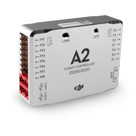
Controller Unit The Control Unit is the core component of the A2 flight control system: M1~M8 are used to connect to the ESCs of the aircraft. The built-in Receiver DR16 is based on DJI DESST technology, which can be used with the Futaba FASST series and DJI DESST series Transmitter. - Page 7 90-degree angle. DO NOT bend or wind them. Receiver System The A2 flight control system can use its own built-in Receiver, and also can support external receivers. Whatever type of Receiver is used, please make sure that the Receiver and Transmitter is linked correctly before use.
- Page 8 “i” stop and then power cycle the system. · At the “i”stop, the D-BUS ADAPTER is converting the PWM signal from traditional receiver to S-BUS signal. Receiver DSM2 Satellite Receiver ©2013 DJI Innovations. All Rights Reserved...
- Page 9 Check the double faced adhesive tape regularly to make sure that the IMU is fixed firmly. There is a CAN-Bus connector, which can be used to connect to the GPS-COMPASS PRO or other DJI product. ©2013 DJI Innovations. All Rights Reserved...
- Page 10 Please always keep the compass module away from magnet fields. Otherwise it may damage the compass module and lead the aircraft to work abnormally or even be out of control. 10 | ©2013 DJI Innovations. All Rights Reserved...
- Page 11 Communicating Indicator of autopilot system Antenna of Bluetooth Mounting Requirements: Mount in a good position to make sure the LED is visible during flying. Antenna of Bluetooth should be unobscured. 11 | ©2013 DJI Innovations. All Rights Reserved...
-
Page 12: Software Installation And Configuration
Configure the A2 flight control system in the Assistant software please adheres to this section. Users are required to configure every item in “Basic” page when use the A2 flight control system for the first time. 1.2.1 Install Driver and Assistant Software 1. -
Page 13: Configuration Checking
Advanced configuration, users can configure it according to their requirements after reading the ○ ⑦~ manual. ○ Check the Channel Map between the Transmitter and A2 flight control system. 13 | ©2013 DJI Innovations. All Rights Reserved... -
Page 14: Compass Calibration
Mechanical structures of the aircraft has changed Drifting during flying Evident drifts occurred in flight such as the aircraft doesn’t fly straight Attitude errors LED often blinks error indicator when the aircraft turns around. 14 | ©2013 DJI Innovations. All Rights Reserved... -
Page 15: Basic Flying
Good GPS signal GPS signal bad *Default is Manual, users can set to ATTI.1 in Assistant software. The biggest difference between ATTI.1 and ATTI.2 is that they are working differently in the protection situations. 15 | ©2013 DJI Innovations. All Rights Reserved... -
Page 16: Flying Environment Requirements
IMU and GPS-COMPASS PRO firmly mounted In addition, check the following items to make sure the system can work. The Transmitter battery is fully charged. The aircraft battery is fully charged. Do not over load the aircraft. 16 | ©2013 DJI Innovations. All Rights Reserved... -
Page 17: Power On And Check
The throttle sticks is under 10% for more than 3secs after motors start. The throttle sticks is under 10% for more than 3secs after landing. The throttle sticks is under 10% for more than 3secs and the inclined angle of aircraft exceeds 70°。 17 | ©2013 DJI Innovations. All Rights Reserved... -
Page 18: Basic Flying Test
When both roll and pitch sticks are at midpoint: GPS mode: the aircraft will be stabilized and locked in horizontal Pitch position. ATTI 1/ATTI 2 mode: the aircraft Stick will be stabilized but unlocked in horizontal position. 18 | ©2013 DJI Innovations. All Rights Reserved... - Page 19 Moreover, you may come across the following abnormal situation, please carry out the operation below. Compass data is abnormal; the LED blinks yellow and green alternatively. Please re-calibrate the Compass. IMU data is abnormal, the LED blinks four green. Please contact your dealer. 19 | ©2013 DJI Innovations. All Rights Reserved...
-
Page 20: Protection Functions Setting
It is recommended to set the Go Home switch in the Assistant software. Users are suggested to enter Failsafe and go home by using the Go Home switch rather than turning off the Transmitter in 20 | ©2013 DJI Innovations. All Rights Reserved... -
Page 21: Low Voltage Protection
Please pay attention to the LED alert of low voltage and make sure the power is enough for go home and landing. Insufficient power reserve will cause the aircraft to crash and other consequences. 21 | ©2013 DJI Innovations. All Rights Reserved... -
Page 22: Advanced Functions
Transmitter to set as IOC switch, which is used to select the different IOC modes and manually record the Forward direction, HP and POI recording. Below are the three options of IOC switch setting which may be configured in the Assistant software. Switch positions 22 | ©2013 DJI Innovations. All Rights Reserved... - Page 23 Please study the following diagram then make a IOC flying test. IOC LED indicator blinks ( (2) means stick(s) not at the midpoint) Flying direction Forward direction Route Auxiliary line 23 | ©2013 DJI Innovations. All Rights Reserved...
- Page 24 During HL flying if one of the following conditions occur, the flight control system will exit HL and enter into CL: the aircraft is within of 10m from HP; the control mode is changed to ATTI 1 or ATTI2; <6(LED 24 | ©2013 DJI Innovations. All Rights Reserved...
-
Page 25: Gimbal Function
Select Course lock or home lock mode for flying the aircraft into a safe area to land when the aircraft is far away or the attitude can’t be recognized. 25 | ©2013 DJI Innovations. All Rights Reserved... -
Page 26: Appendix
(3), please hover or land the aircraft and wait for the white LED to go off. When the LED blinks (3), it is not recommended to fly. When the LED blinks (4), please contact your dealer. 26 | ©2013 DJI Innovations. All Rights Reserved... -
Page 27: Specifications
Hovering Accuracy (In GPS Mode) Vertical: ± 0.5m Horizontal: ± 1.5m Maximum Wind Resistance <8m/s (17.9mph / 28.8km/h) Max Yaw Angular Velocity 150deg/s Max Tilt Angle 35° Ascent / Descent 6m/s 27 | ©2013 DJI Innovations. All Rights Reserved... -
Page 28: Faq
The A2 can be used with other DJI products such as iOSD Mark II, Z15, S800 EVO and 2.4G Data Link (Coming soon) etc. The following diagram is the connection for your reference. 2S~6S Battery 2S~6S Battery Coming soon 28 | ©2013 DJI Innovations. All Rights Reserved... -
Page 29: Channel Mapping Instructions For Pc Assistant Software
Receiver channel. If you enable the Gimbal function Unit) of Controller Unit, unmapped. in Assistant Software, then the F3/F2 are used for gimbal control. Even D3/D2 are mapped to Receiver channels, the output signal from the corresponding 29 | ©2013 DJI Innovations. All Rights Reserved... -
Page 30: Recommended Mapping For Futaba Transmitter (Mode 2) User
Motor Propeller Battery Weight Pitch Roll Pitch Roll Vertical F450 DJI-2212 DJI-30A DJI-8 Inch 3S-2200 890 g F550 DJI-2212 DJI-30A DJI-8 Inch 4S-3300 1530 g S800 EVO+Z15 DJI-4114 DJI-40A DJI-15Inch 6S-15000 7000g 30 | ©2013 DJI Innovations. All Rights Reserved... -
Page 31: Disclaimer
This product and manual are copyrighted by DJI Innovations with all rights reserved. No part of this product or manual shall be reproduced in any form without the prior written consent or authorization of DJI Innovations. No patent liability is assumed with respect to the use of the product or information contained herein.
Need help?
Do you have a question about the A2 Flight Control System and is the answer not in the manual?
Questions and answers