Table of Contents
Advertisement
Quick Links
Uncontrolled if printed
A i r p l a n e I n f o r m a t i o n M a n u a l
1 0 0 S E R I E S A I R C R A F T
WA R N I N G / N O T I C E
At the time of issuance, this information manual was an exact
duplicate of the flight information contained within the Pilot's
Operating Handbook and FAA Approved Airplane Flight Manual.
The information contained within this manual is to be used for
general purposes only and may NOT substitute for the official Pilot's
Operating Handbook. The information within this manual was
current as of the date listed below, and is for reference only.
DO NOT USE THIS MANUAL FOR
FLIGHT OPERATIONS
Q U E S T A I R C R A F T C O M PA N Y
1 2 0 0 T u r b i n e D r i v e
S a n d p o i n t , I D 8 3 8 6 4
P h o n e : ( 2 0 8 ) 2 6 3 - 1111
F a x : ( 2 0 8 ) 2 6 3 - 1 5 11
w w w . q u e s t a i r c r a f t . c o m
( D O C U M E N T N O : A M 9 0 1 . 2 0 1 )
Rev i s i o n 16
Fe b r u a r y 2 015
PREFACE-1
Advertisement
Chapters
Table of Contents

Summary of Contents for Kodiak 100 Series
- Page 1 Uncontrolled if printed A i r p l a n e I n f o r m a t i o n M a n u a l ( D O C U M E N T N O : A M 9 0 1 . 2 0 1 ) 1 0 0 S E R I E S A I R C R A F T WA R N I N G / N O T I C E At the time of issuance, this information manual was an exact...
- Page 2 Uncontrolled if printed 1 0 0 S E R I E S This Page Intentionally Left Blank PREFACE- 2 P i l o t ’s O p e r a t i n g H a n d b o o k D O N OT U S E FO R FL I G H T O PE R AT I O N S...
- Page 3 Uncontrolled if printed 1 0 0 S E R I E S Table of Sections CONTENTS SECTION GENERAL ........................ 1 LIMITATIONS ......................2 EMERGENCY PROCEDURES ................3 ABNORMAL PROCEDURES ................3A NORMAL PROCEDURES ..................4 PERFORMANCE ...................... 5 WEIGHT AND BALANCE ..................6 AIRPLANE &...
- Page 4 Uncontrolled if printed 1 0 0 S E R I E S 1 0 0 S E R I E S This Page Intentionally Left Blank PREFACE- 4 P i l o t ’s O p e r a t i n g H a n d b o o k D O N OT U S E FO R FL I G H T O PE R AT I O N S...
-
Page 5: Table Of Contents
Uncontrolled if printed S e c t i o n 1 G E N E R A L 1 0 0 S E R I E S SECTION 1 GENERAL Table of Contents CONTENTS PAGE GENERAL ......................1-3 INTRODUCTION ....................1-3 THREE VIEW DRAWING ..................1-3 DESCRIPTIVE DATA ....................1-5 ENGINE ......................1-5 PROPELLER ......................1-5... - Page 6 Uncontrolled if printed S e c t i o n 1 G E N E R A L 1 0 0 S E R I E S This Page Intentionally Left Blank 1- 2 P i l o t ’s O p e r a t i n g H a n d b o o k D O N OT U S E FO R FL I G H T O PE R AT I O N S...
-
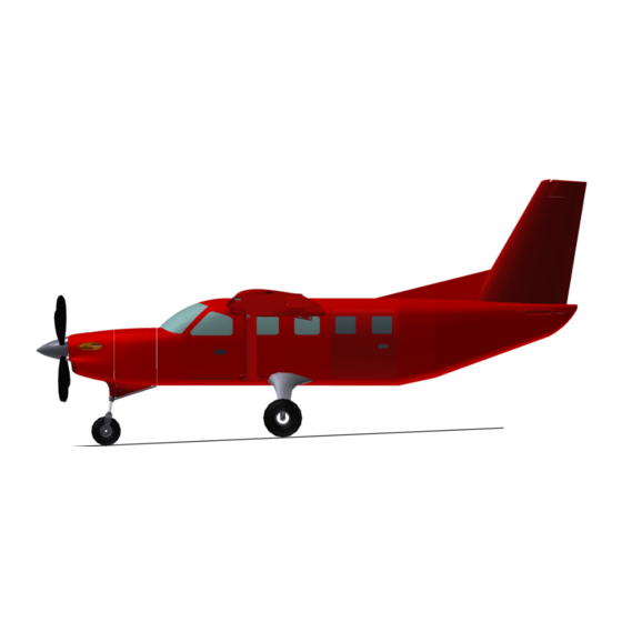
Page 7: General
English version will control. 1-3 THREE VIEW DRAWING See Figure 1-1 for a general arrangement drawing of the KODIAK 100. P i l o t ’s O p e r a t i n g H a n d b o o k... - Page 8 Uncontrolled if printed S e c t i o n 1 G E N E R A L 1 0 0 S E R I E S 33.8 ft 45.0 ft Wing Area: 240 sq.ft. Minimum Turning Radius: 152 in (Main Landing Gear to Nose Landing Gear) Max.
-
Page 9: Descriptive Data
Uncontrolled if printed S e c t i o n 1 G E N E R A L 1 0 0 S E R I E S 1-4 DESCRIPTIVE DATA ENGINE Number of Engines: 1 Engine Manufacturer: Pratt & Whitney Canada Engine Model Number: PT6A-34 Engine Type: The PT6A series engine is a free power, two-shaft turbine engine. -
Page 10: Fuel
1 0 0 S E R I E S FUEL The following fuels and fuel additives are FAA approved for use on the KODIAK 100, subject to the limitations and requirements given in “Section 2” of this manual. Issuing Authority Approved Fuel Grade Freezing Point °C (°F) -
Page 11: Oil
Uncontrolled if printed S e c t i o n 1 G E N E R A L 1 0 0 S E R I E S Oil Grade (Specification): Engine oil must conform to the current revision of Pratt & Whitney Canada “Service Bulletin No. 1001.” Refer to “Section 8” of this manual for a listing of approved oils. -
Page 12: Cabin, Cargo, And Entry Dimensions
Uncontrolled if printed S e c t i o n 1 G E N E R A L 1 0 0 S E R I E S CABIN, CARGO, AND ENTRY DIMENSIONS Maximum Cabin Width ..............54.0 IN Maximum Cabin Height ..............57.0 IN Cabin Length (Forward Door Post to Aft Bulkhead) ......190 IN Minimum Crew Door Width ..............31 IN Minimum Crew Door Height ..............51 IN... -
Page 13: Symbols, Abbreviations, And Terminology
Uncontrolled if printed S e c t i o n 1 G E N E R A L 1 0 0 S E R I E S 1-5 SYMBOLS, ABBREVIATIONS, AND TERMINOLOGY GENERAL AIRSPEED TERMINOLOGY AND ABBREVIATIONS KCAS - Knots Calibrated Airspeed – The indicated airspeed of an airplane expressed in knots, corrected for position and instrument error. -
Page 14: Meteorological Terminology
Uncontrolled if printed S e c t i o n 1 G E N E R A L 1 0 0 S E R I E S METEOROLOGICAL TERMINOLOGY ISA - International Standard Atmosphere – Atmospheric conditions in which: 1. The air is a dry, perfect gas. 2. - Page 15 Uncontrolled if printed S e c t i o n 1 G E N E R A L 1 0 0 S E R I E S Maximum Continuous Power – The maximum power rating, limited to emergency or abnormal conditions only, which require maximum aircraft performance, for example, extreme icing conditions or excessive downdrafts.
-
Page 16: Airplane Performance And Flight Planning Terminology
Uncontrolled if printed S e c t i o n 1 G E N E R A L 1 0 0 S E R I E S AIRPLANE PERFORMANCE AND FLIGHT PLANNING TERMINOLOGY Climb Gradient – The demonstrated ratio of the change in height during a portion of a climb, to the horizontal distance traversed in the same time interval. - Page 17 Uncontrolled if printed S e c t i o n 1 G E N E R A L 1 0 0 S E R I E S MAC - Mean Aerodynamic Chord of a wing is the chord of an imaginary airfoil which will have the same force vectors as those of the actual wing, throughout the flight range.
-
Page 18: Warnings, Cautions, And Notes Defined
Uncontrolled if printed S e c t i o n 1 G E N E R A L 1 0 0 S E R I E S WARNINGS, CAUTIONS, AND NOTES DEFINED WARNI N G: An operating procedure, technique, note, or maintenance practice which may result in personal injury or death if not carefully followed. -
Page 19: Kilograms And Pounds
Uncontrolled if printed S e c t i o n 1 G E N E R A L 1 0 0 S E R I E S KILOGRAMS AND POUNDS NOTE : Example of how to use the following table: To convert 87 kilograms to pounds, locate the 80 in the first column and then move right, horizontally to column number 7 and read the solution: 87 kilograms = 191.80 pounds. -
Page 20: Nautical Miles, Statute Miles, And Kilometers
Uncontrolled if printed S e c t i o n 1 G E N E R A L 1 0 0 S E R I E S NAUTICAL MILES, STATUTE MILES, AND KILOMETERS Nautical Statute Nautical Statute Nautical Statute Kilometers Kilometers Kilometers Miles... -
Page 21: Liters, Imperial Gallons, And U.s. Gallons
Uncontrolled if printed S e c t i o n 1 G E N E R A L 1 0 0 S E R I E S LITERS, IMPERIAL GALLONS, AND U.S. GALLONS Converting Liters to Imperial Gallons Liters 0.00 0.22 0.44 0.66... - Page 22 Uncontrolled if printed S e c t i o n 1 G E N E R A L 1 0 0 S E R I E S Converting Liters to U.S. Gallons Liters 0.00 0.26 0.53 0.79 1.06 1.32 1.59 1.85 2.11 2.38...
- Page 23 Uncontrolled if printed S e c t i o n 1 G E N E R A L 1 0 0 S E R I E S Converting Imperial Gallons to U.S. Gallons Imperial Gallons 0.00 1.20 2.40 3.60 4.80 6.01 7.21 8.41...
-
Page 24: Temperature Conversion Chart
Uncontrolled if printed S e c t i o n 1 G E N E R A L 1 0 0 S E R I E S TEMPERATURE CONVERSION CHART • Conversion values are TEMP TO TEMP TO TEMP TO rounded. - Page 25 Uncontrolled if printed S e c t i o n 2 L I M I TAT I O N S 1 0 0 S E R I E S SECTION 2 Limitations Table of Contents CONTENTS PAGE GENERAL ......................2-3 AIRSPEED LIMITATIONS ..................2-4 AIRSPEED INDICATOR MARKINGS ..............2-4 POWERPLANT LIMITATIONS ................2-5 PROPELLER SYSTEM OPERATING LIMITATIONS .........2-6...
- Page 26 Uncontrolled if printed S e c t i o n 2 L I M I TAT I O N S 1 0 0 S E R I E S This Page Intentionally Left Blank 2 - 2 P i l o t ’s O p e r a t i n g H a n d b o o k D O N OT U S E FO R FL I G H T O PE R AT I O N S...
-
Page 27: General
The airspeeds listed in this section are based on airspeed calibration data shown in “Section 5” of this manual. Your KODIAK is certificated under FAA Type Certificate Number A00007SE as a Quest Aircraft Company KODIAK 100. P i l o t ’s O p e r a t i n g H a n d b o o k... -
Page 28: Airspeed Limitations
Uncontrolled if printed S e c t i o n 2 L I M I TAT I O N S 1 0 0 S E R I E S 2-2 AIRSPEED LIMITATIONS Airspeed limitations and their operational significance are provided in the table below. -
Page 29: Powerplant Limitations
Uncontrolled if printed S e c t i o n 2 L I M I TAT I O N S 1 0 0 S E R I E S KIAS Marking Value or Significance Range Full Flap Operating Range – The lower limit of the white arc represents the stall speed at maximum gross White Arc 47 to 108... -
Page 30: Propeller System Operating Limitations
Uncontrolled if printed S e c t i o n 2 L I M I TAT I O N S 1 0 0 S E R I E S PROPELLER SYSTEM OPERATING LIMITATIONS An overspeed governor test must be performed prior to the first flight of the day and following engine control system maintenance or adjustments. - Page 31 Uncontrolled if printed S e c t i o n 2 L I M I TAT I O N S 1 0 0 S E R I E S Maximum Generator Propeller Pressure Temp. Operation Torque ITT°C PSIG °C 1790 2200 750 @ Takeoff...
-
Page 32: Power Plant Instrument Markings
Uncontrolled if printed S e c t i o n 2 L I M I TAT I O N S 1 0 0 S E R I E S 2-5 POWER PLANT INSTRUMENT MARKINGS Marking designations for the power plant instruments are provided in the table below and the figure on the following page. - Page 33 Uncontrolled if printed S e c t i o n 2 L I M I TAT I O N S 1 0 0 S E R I E S Torque Indicator Gas Generator RPM Indicator ITT Indicator Oil Pressure Indicator (Normal Operation) Oil Temperature Indicator ITT Indicator (Engine Start)
-
Page 34: Miscellaneous Instrument Markings
Minimum Flying Weight ..............4070 lb NOT E : Refer to “Section 6” of this manual for cabin zone loading limits of the KODIAK 100. Refer to “Section 5” of this manual for takeoff limits based on weight, altitude and temperature. 2-10 P i l o t ’s O p e r a t i n g H a n d b o o k... -
Page 35: Center Of Gravity Limits
4000 3500 C.G. LOCATION (% MAC) Maximum Zero Fuel Weight (MZFW) Figure 2-2 – KODIAK Loading Envelope NOT E: Any weight above the maximum zero fuel weight of 6490 lb must be in the form of fuel. P i l o t ’s O p e r a t i n g H a n d b o o k... -
Page 36: Maneuver Limits
Uncontrolled if printed S e c t i o n 2 L I M I TAT I O N S 1 0 0 S E R I E S 2-9 MANEUVER LIMITS This airplane is certified in the normal category. The normal category is applicable to aircraft not intended for aerobatic operations. - Page 37 1 0 0 S E R I E S Kinds of Operation Equipment List System, Instrument, Equipment and/or Function Comments Placards and Markings KODIAK 100 POH/AFM Accessible to pilot in flight. Garmin G1000™ Cockpit Accessible to pilot in flight. Reference Guide Autoflight...
- Page 38 Uncontrolled if printed S e c t i o n 2 L I M I TAT I O N S 1 0 0 S E R I E S Kinds of Operation Equipment List System, Instrument, Equipment and/or Function Comments Flight Controls Flap Position Indicator Flap Operating System...
- Page 39 Uncontrolled if printed S e c t i o n 2 L I M I TAT I O N S 1 0 0 S E R I E S Kinds of Operation Equipment List System, Instrument, Equipment and/or Function Comments G1000 Annunciations ALTERNATR FL (Amber) AUX PUMP ON (White)
- Page 40 Uncontrolled if printed S e c t i o n 2 L I M I TAT I O N S 1 0 0 S E R I E S Kinds of Operation Equipment List System, Instrument, Equipment and/or Function Comments G1000 Annunciations (cont.) RESERVOIR FUEL (Red) STARTER ON (White)
- Page 41 Uncontrolled if printed S e c t i o n 2 L I M I TAT I O N S 1 0 0 S E R I E S Kinds of Operation Equipment List System, Instrument, Equipment and/or Function Comments Navigation and Pitot-Static System (cont.) G1000 Turn Coordinator...
-
Page 42: Fuel Limitations
Uncontrolled if printed S e c t i o n 2 L I M I TAT I O N S 1 0 0 S E R I E S 2-13 FUEL LIMITATIONS TOTAL FUEL CAPACITY Both Tanks ............320 U.S. Gallons (2177 lb) Each Tank ............160 U.S. -
Page 43: Maximum Operating Altitude Limitation
Uncontrolled if printed S e c t i o n 2 L I M I TAT I O N S 1 0 0 S E R I E S 2. The aircraft has been continuously parked or operated at or above 5°C since the last flight when the fuel system contained specified concentrations of DIEGME anti-icing fuel additive, AND 3. -
Page 44: Maximum Passenger Seating Limit
Uncontrolled if printed S e c t i o n 2 L I M I TAT I O N S 1 0 0 S E R I E S 2-16 MAXIMUM PASSENGER SEATING LIMIT Up to ten seats may be installed. The right front seat may be occupied by either a passenger or a second crew member. -
Page 45: Garmin G1000 Operational Limitations
Uncontrolled if printed S e c t i o n 2 L I M I TAT I O N S 1 0 0 S E R I E S GARMIN G1000 OPERATIONAL LIMITATIONS The pilot should be aware that, due to variation in the earth’s magnetic field, operating the Garmin G1000 system within the following areas could result in loss of reliable attitude and heading indications. -
Page 46: Placards
Uncontrolled if printed S e c t i o n 2 L I M I TAT I O N S 1 0 0 S E R I E S 2-18 PLACARDS The following information must be displayed in the form of placards or markings, in the approximate locations given. - Page 47 Uncontrolled if printed S e c t i o n 2 L I M I TAT I O N S 1 0 0 S E R I E S 5. Located above the MFD: TORQUE LIMITS 2200 RPM 2000 RPM CLIMB &...
- Page 48 Uncontrolled if printed S e c t i o n 2 L I M I TAT I O N S 1 0 0 S E R I E S 11. Located on the engine control pedestal: 12. Located near the trim disconnect switch on each yoke if airplane is equipped with STEC Autopilot: 2 - 2 4 P i l o t ’s O p e r a t i n g H a n d b o o k...
- Page 49 Uncontrolled if printed S e c t i o n 2 L I M I TAT I O N S 1 0 0 S E R I E S 13. Located near the firewall fuel shutoff valve: FIREWALL FUEL SHUTOFF PULL OFF 14.
- Page 50 Uncontrolled if printed S e c t i o n 2 L I M I TAT I O N S 1 0 0 S E R I E S 17. Located near the forward cabin curtain: CURTAIN MUST BE STOWED AND SECURED DURING TAXI, TAKEOFF, TURBULENCE AND LANDING...
- Page 51 Uncontrolled if printed S e c t i o n 2 L I M I TAT I O N S 1 0 0 S E R I E S 23. Located at each cockpit fire extinguisher: FIRE EXTINGUISHER 100-750-0012 23a. Located at each fire extinguisher (alternative to #23): 24.
- Page 52 Uncontrolled if printed S e c t i o n 2 L I M I TAT I O N S 1 0 0 S E R I E S 28. Located on the interior just aft of the cargo door, at a height greater than the top of the passenger seat: TO CLOSE DOOR: STOW EXTERIOR...
- Page 53 Uncontrolled if printed S e c t i o n 2 L I M I TAT I O N S 1 0 0 S E R I E S 31. Located on the interior of the lower cargo door: 32. Located on the interior of the upper cargo door: DOOR OPENING INSTRUCTIONS PULL ROTATE...
- Page 54 Uncontrolled if printed S e c t i o n 2 L I M I TAT I O N S 1 0 0 S E R I E S 35. Located on the interior of the upper cargo door: 36. Located on the exterior of the cargo door: LOWER DOOR 100-910-0048 HANDLE ON...
- Page 55 Uncontrolled if printed S e c t i o n 2 L I M I TAT I O N S 1 0 0 S E R I E S 38. Located on the exterior of each door as appropriate: 39. Located on the exterior of each crew door as appropriate: 40.
- Page 56 Uncontrolled if printed S e c t i o n 2 L I M I TAT I O N S 1 0 0 S E R I E S 41. Located on the oxygen bottle: WARNING: FILL WITH AVIATORS OXYGEN ONLY! MAXIMUM FILL RATE: 200 psi / min.
- Page 57 Uncontrolled if printed S e c t i o n 2 L I M I TAT I O N S 1 0 0 S E R I E S 44. Located on the battery trays: 45. Located near the ground power service receptacle: EXTERNAL POWER 28 VOLTS DC NOMINAL 800 AMPS...
- Page 58 Uncontrolled if printed S e c t i o n 2 L I M I TAT I O N S 1 0 0 S E R I E S 47. Located on the side of the oil-to-fuel heater near the oil filler cap: 48.
- Page 59 Uncontrolled if printed S e c t i o n 2 L I M I TAT I O N S 1 0 0 S E R I E S 52. Located on the wings, adjacent to each inboard fuel tank filler cap: JET FUEL ONLY 96.5...
-
Page 60: Optional System Placards
Uncontrolled if printed S e c t i o n 2 L I M I TAT I O N S 1 0 0 S E R I E S OPTIONAL SYSTEM PLACARDS NOT E : Refer to “Section 9” of this manual for supplemental placards associated with optional systems. - Page 61 Uncontrolled if printed S e c t i o n 3 E M E R G E N CY P R O C E D U R E S 1 0 0 S E R I E S SECTION 3 EMERGENCY PROCEDURES Table of Content CONTENTS...
- Page 62 Uncontrolled if printed S e c t i o n 3 E M E R G E N CY P R O C E D U R E S 1 0 0 S E R I E S ELECTRICAL POWER SUPPLY MALFUNCTIONS .........3-27 Loss of Electrical Power ................3-27 INADVERTENT FLIGHT INTO ICING CONDITIONS .........3-27 ICE FORMATION DETERMINATION ...............3-27...
-
Page 63: Emergency Procedures
Uncontrolled if printed S e c t i o n 3 E M E R G E N CY P R O C E D U R E S 1 0 0 S E R I E S 3-1 GENERAL This section of the Pilot’s Operating Handbook describes the recommended procedures for managing various types of emergencies or critical situations that may occur. -
Page 64: Airspeeds For Emergency Operations
Uncontrolled if printed S e c t i o n 3 E M E R G E N CY P R O C E D U R E S 1 0 0 S E R I E S 3-2 AIRSPEEDS FOR EMERGENCY OPERATIONS Maneuvering Speed (V 7255 Pounds .................142 KIAS 6750 Pounds .................137 KIAS... -
Page 65: Emergency Procedures Checklist
Uncontrolled if printed S e c t i o n 3 E M E R G E N CY P R O C E D U R E S 1 0 0 S E R I E S 3-3 EMERGENCY PROCEDURES CHECKLIST The following checklist is provided in case of emergency malfunctions with the airplane or powerplant system. - Page 66 Uncontrolled if printed S e c t i o n 3 E M E R G E N CY P R O C E D U R E S 1 0 0 S E R I E S Engine Flameout During Flight If N is above 52%: 1.
-
Page 67: Airstart
Uncontrolled if printed S e c t i o n 3 E M E R G E N CY P R O C E D U R E S 1 0 0 S E R I E S AIRSTART Starter Assisted Airstart (Preferred Method) 1. - Page 68 Uncontrolled if printed S e c t i o n 3 E M E R G E N CY P R O C E D U R E S 1 0 0 S E R I E S Not Starter Assisted Airstart 1.
- Page 69 Uncontrolled if printed S e c t i o n 3 E M E R G E N CY P R O C E D U R E S 1 0 0 S E R I E S SMOKE AND FIRE Engine Fire in Flight 1.
- Page 70 Uncontrolled if printed S e c t i o n 3 E M E R G E N CY P R O C E D U R E S 1 0 0 S E R I E S Cabin Fire (continued) 1.
-
Page 71: Emergency Descent
Uncontrolled if printed S e c t i o n 3 E M E R G E N CY P R O C E D U R E S 1 0 0 S E R I E S EMERGENCY DESCENT Emergency Descent (Low Altitude) 1. -
Page 72: Glide
Uncontrolled if printed S e c t i o n 3 E M E R G E N CY P R O C E D U R E S 1 0 0 S E R I E S GLIDE Glide 1. -
Page 73: Landing Emergencies
Uncontrolled if printed S e c t i o n 3 E M E R G E N CY P R O C E D U R E S 1 0 0 S E R I E S LANDING EMERGENCIES Engine Out Emergency Landing 1. - Page 74 Uncontrolled if printed S e c t i o n 3 E M E R G E N CY P R O C E D U R E S 1 0 0 S E R I E S Ditching WARN I NG : This airplane has not been tested in actual ditching (emergency water landing).
-
Page 75: System Emergencies
Uncontrolled if printed S e c t i o n 3 E M E R G E N CY P R O C E D U R E S 1 0 0 S E R I E S SYSTEM EMERGENCIES Engine Emergencies Loss of Oil Pressure OIL PRESS LOW... -
Page 76: S-Tec Autopilot Malfunction
Uncontrolled if printed S e c t i o n 3 E M E R G E N CY P R O C E D U R E S 1 0 0 S E R I E S S-TEC Autopilot Malfunction Any failure or malfunction of the electric trim or autopilot can be overridden by use of the control yoke. -
Page 77: Fuel System Emergencies
Uncontrolled if printed S e c t i o n 3 E M E R G E N CY P R O C E D U R E S 1 0 0 S E R I E S Fuel System Emergencies Loss of Fuel Pressure FUEL PRESS LOW annunciation shown on PFD) - Page 78 Uncontrolled if printed S e c t i o n 3 E M E R G E N CY P R O C E D U R E S 1 0 0 S E R I E S INADVERTENT FLIGHT INTO ICING CONDITIONS Inadvertent Icing Encounter 1.
-
Page 79: Amplified Emergency Procedures
Uncontrolled if printed S e c t i o n 3 E M E R G E N CY P R O C E D U R E S 1 0 0 S E R I E S 3-4 AMPLIFIED EMERGENCY PROCEDURES The following Amplified Emergency Procedures elaborate upon information contained in the Emergency Procedures Checklist portion of this Section. -
Page 80: Engine Failure During Flight
Uncontrolled if printed S e c t i o n 3 E M E R G E N CY P R O C E D U R E S 1 0 0 S E R I E S Engine Failure During Flight Following an engine failure in flight, establish the best glide speed as soon as possible. -
Page 81: Airstart
Uncontrolled if printed S e c t i o n 3 E M E R G E N CY P R O C E D U R E S 1 0 0 S E R I E S AIRSTART If an airstart is to be attempted, the checklist procedures should be followed. The Starter Assisted procedure is the preferred method since it results in cooler starting temperatures. -
Page 82: Engine Fire
Uncontrolled if printed S e c t i o n 3 E M E R G E N CY P R O C E D U R E S 1 0 0 S E R I E S Engine Fire Engine fires may be caused by a malfunction with the fuel control unit or improper starting techniques. -
Page 83: Landing Emergencies
Uncontrolled if printed S e c t i o n 3 E M E R G E N CY P R O C E D U R E S 1 0 0 S E R I E S LANDING EMERGENCIES Forced Landings If all attempts to restart the engine fail and a forced landing is imminent, choose a suitable landing area and prepare for the landing as outlined in the... -
Page 84: Engine System Emergencies
Uncontrolled if printed S e c t i o n 3 E M E R G E N CY P R O C E D U R E S 1 0 0 S E R I E S ENGINE SYSTEM EMERGENCIES Loss of Engine Oil Pressure OIL PRESS LOW annunciation will display on the PFD when the oil... -
Page 85: Engine Inlet Bypass Failure
Uncontrolled if printed S e c t i o n 3 E M E R G E N CY P R O C E D U R E S 1 0 0 S E R I E S Engine Inlet Bypass Failure INLET NOT BP annunciation will display on the PFD when the Engine Inlet Bypass fails to reach the BYPASS position. -
Page 86: Fuel System Malfunctions
Uncontrolled if printed S e c t i o n 3 E M E R G E N CY P R O C E D U R E S 1 0 0 S E R I E S FUEL SYSTEM MALFUNCTIONS Fuel Flow Interruption Fuel flows by gravity from the wing tanks, through the fuel tank shutoff/ selector valves at the inboard portion of each wing tank, to the reservoir... -
Page 87: Electrical Power Supply Malfunctions
Uncontrolled if printed S e c t i o n 3 E M E R G E N CY P R O C E D U R E S 1 0 0 S E R I E S ELECTRICAL POWER SUPPLY MALFUNCTIONS Loss of Electrical Power For increased redundancy, the electrical system includes two 24 volt batteries, a starter/generator and an alternator, all of which may provide electrical power... -
Page 88: Spins
Uncontrolled if printed S e c t i o n 3 E M E R G E N CY P R O C E D U R E S 1 0 0 S E R I E S 3-6 SPINS WARN I NG : This airplane is certified in the normal category and intentional spinning of the aircraft is prohibited. - Page 89 Uncontrolled if printed S e c t i o n 3 A A B N O R M A L P R O C E D U R E S 1 0 0 S E R I E S SECTION 3A ABNORMAL PROCEDURES Table of Contents CONTENTS...
- Page 90 Uncontrolled if printed S e c t i o n 3 A A B N O R M A L P R O C E D U R E S 1 0 0 S E R I E S This Page Intentionally Left Blank 3 A - 2 P i l o t ’s O p e r a t i n g H a n d b o o k D O N OT U S E FO R FL I G H T O PE R AT I O N S...
-
Page 91: General
Uncontrolled if printed S e c t i o n 3 A A B N O R M A L P R O C E D U R E S 1 0 0 S E R I E S 3A-1 GENERAL This section of the Pilot’s Operating Handbook describes the recommended procedures for managing various types of abnormal procedures or malfunctions that may occur. - Page 92 Uncontrolled if printed S e c t i o n 3 A A B N O R M A L P R O C E D U R E S 1 0 0 S E R I E S Torque 1.
-
Page 93: Electrical Power Supply System Malfunctions
Uncontrolled if printed S e c t i o n 3 A A B N O R M A L P R O C E D U R E S 1 0 0 S E R I E S ELECTRICAL POWER SUPPLY SYSTEM MALFUNCTIONS Generator Failure VOLTAGE LOW and/or... -
Page 94: Trim System Malfunctions
Uncontrolled if printed S e c t i o n 3 A A B N O R M A L P R O C E D U R E S 1 0 0 S E R I E S TRIM SYSTEM MALFUNCTIONS Elevator Trim Failure (Elevator trim fails to operate when commanded) 1. -
Page 95: Flap System Malfunctions
Uncontrolled if printed S e c t i o n 3 A A B N O R M A L P R O C E D U R E S 1 0 0 S E R I E S FLAP SYSTEM MALFUNCTIONS Flaps Fail to Extend or Retract FLAP FAIL annunciation shown on PFD) -
Page 96: Abnormal Navigation System Failures
Uncontrolled if printed S e c t i o n 3 A A B N O R M A L P R O C E D U R E S 1 0 0 S E R I E S ABNORMAL NAVIGATION SYSTEM FAILURES Attitude Heading Reference System (AHRS) Failures Single AHRS Failure 1. - Page 97 Uncontrolled if printed S e c t i o n 3 A A B N O R M A L P R O C E D U R E S 1 0 0 S E R I E S GPS/NAV Computer System Failures #1 GPS/NAV Failure 1.
- Page 98 Uncontrolled if printed S e c t i o n 3 A A B N O R M A L P R O C E D U R E S 1 0 0 S E R I E S Primary Flight Display (PFD) Failure #1 PFD Failure Annunciations Shown on MFD: •...
-
Page 99: Abnormal Landing Procedures
Uncontrolled if printed S e c t i o n 3 A A B N O R M A L P R O C E D U R E S 1 0 0 S E R I E S ABNORMAL LANDING PROCEDURES Landing with a Flat Main Tire 1. -
Page 100: Inadvertent Opening Of Doors In Flight
Uncontrolled if printed S e c t i o n 3 A A B N O R M A L P R O C E D U R E S 1 0 0 S E R I E S INADVERTENT OPENING OF DOORS IN FLIGHT Right or Left Crew Door Open 1. -
Page 101: Abnormal Navigation System Failures
Uncontrolled if printed S e c t i o n 3 A A B N O R M A L P R O C E D U R E S 1 0 0 S E R I E S 3A-4 ABNORMAL NAVIGATION SYSTEM FAILURES ATTITUDE HEADING REFERENCE SYSTEM (AHRS) FAILURES Single AHRS Failure... - Page 102 Uncontrolled if printed S e c t i o n 3 A A B N O R M A L P R O C E D U R E S 1 0 0 S E R I E S Dual AHRS Failure (Red “X” – Heading and Attitude Indicators) If both AHRS systems fail, check that both AHRS circuit breakers are pushed in.
-
Page 103: Air Data Computer (Adc) System Failures
Uncontrolled if printed S e c t i o n 3 A A B N O R M A L P R O C E D U R E S 1 0 0 S E R I E S AIR DATA COMPUTER (ADC) SYSTEM FAILURES Single ADC Failure If a failure occurs in a single ADC system, the other ADC system will automatically provide airspeed and altitude information to both displays if... - Page 104 Uncontrolled if printed S e c t i o n 3 A A B N O R M A L P R O C E D U R E S 1 0 0 S E R I E S Dual ADC Failure (Red “X” – All Air Data Indications) If both ADC systems fail, check that both ADC circuit breakers are pushed in.
-
Page 105: Gps/Nav Computer System Failures
Uncontrolled if printed S e c t i o n 3 A A B N O R M A L P R O C E D U R E S 1 0 0 S E R I E S GPS/NAV COMPUTER SYSTEM FAILURES #1 GPS/NAV Failure If a failure occurs in the #1 GPS/NAV system (GIA), the other GPS/NAV system will automatically provide GPS information to both displays. - Page 106 Uncontrolled if printed S e c t i o n 3 A A B N O R M A L P R O C E D U R E S 1 0 0 S E R I E S Figure 3A-5 – No. 1 GPS/NAV Computer Failure (No.
- Page 107 Uncontrolled if printed S e c t i o n 3 A A B N O R M A L P R O C E D U R E S 1 0 0 S E R I E S #2 GPS/NAV Failure If a failure occurs in the #2 GPS/NAV system (GIA), the other GPS/NAV system will automatically provide GPS information to both displays.
- Page 108 Uncontrolled if printed S e c t i o n 3 A A B N O R M A L P R O C E D U R E S 1 0 0 S E R I E S Dual GPS/NAV Failure If both GPS/NAV (GIA) systems fail, check that both GPS/NAV circuit breakers are pushed in.
-
Page 109: Primary Flight Display (Pfd) Failure
Uncontrolled if printed S e c t i o n 3 A A B N O R M A L P R O C E D U R E S 1 0 0 S E R I E S PRIMARY FLIGHT DISPLAY (PFD) FAILURE #1 PFD Failure If a failure occurs in the #1 Primary Flight Display (Pilot’s PFD) the MFD will automatically enter Reversionary Mode and provide Flight, Navigation,... - Page 110 Uncontrolled if printed S e c t i o n 3 A A B N O R M A L P R O C E D U R E S 1 0 0 S E R I E S NOTE : The alerts box will display GMA 1 FAILURE (audio panel).
-
Page 111: Multi - Function Display (Mfd) Failure
Uncontrolled if printed S e c t i o n 3 A A B N O R M A L P R O C E D U R E S 1 0 0 S E R I E S MULTI – FUNCTION DISPLAY (MFD) FAILURE If a failure occurs in the Multi-Function Display (MFD) both PFD units will automatically enter Reversionary Mode and provide Flight, Navigation, Communication, and Engine information on the displays. - Page 112 Uncontrolled if printed S e c t i o n 3 A A B N O R M A L P R O C E D U R E S 1 0 0 S E R I E S This Page Intentionally Left Blank 3 A - 2 4 P i l o t ’s O p e r a t i n g H a n d b o o k D O N OT U S E FO R FL I G H T O PE R AT I O N S...
- Page 113 Uncontrolled if printed S e c t i o n 4 N O R M A L P R O C E D U R E S 1 0 0 S E R I E S SECTION 4 NORMAL PROCEDURES Table of Contents CONTENTS PAGE...
- Page 114 Uncontrolled if printed S e c t i o n 4 N O R M A L P R O C E D U R E S 1 0 0 S E R I E S This Page Intentionally Left Blank 4 - 2 P i l o t ’s O p e r a t i n g H a n d b o o k D O N OT U S E FO R FL I G H T O PE R AT I O N S...
- Page 115 Uncontrolled if printed S e c t i o n 4 N O R M A L P R O C E D U R E S 1 0 0 S E R I E S 4-1 GENERAL This section of the Pilot’s Operating Handbook includes procedures for conducting normal operations, laid out in checklist format.
-
Page 116: Normal Procedures Checklist
Uncontrolled if printed S e c t i o n 4 S e c t i o n 4 N O R M A L P R O C E D U R E S N O R M A L P R O C E D U R E S 1 0 0 S E R I E S 1 0 0 S E R I E S 4-3 NORMAL PROCEDURES CHECKLIST... - Page 117 Uncontrolled if printed S e c t i o n 4 N O R M A L P R O C E D U R E S 1 0 0 S E R I E S Left Side 1. Fuselage Floor Skin Drain Holes ............CHECK (Check for any sign of leaks in the aircraft sidewall or sub-floor.) NOTE : This check is especially important if your aircraft is equipped with...
- Page 118 Uncontrolled if printed S e c t i o n 4 N O R M A L P R O C E D U R E S 1 0 0 S E R I E S Empennage (continued) 4. Tail Tie Down ................. DISCONNECT (Ensure tail stand removed) 5.
- Page 119 Uncontrolled if printed S e c t i o n 4 N O R M A L P R O C E D U R E S 1 0 0 S E R I E S Nose WAR NI N G: During cold weather operations, it is essential to remove even small traces of frost, ice or snow from the propeller blades, spinner and engine inlets.
-
Page 120: Before Starting Engine
Uncontrolled if printed S e c t i o n 4 N O R M A L P R O C E D U R E S 1 0 0 S E R I E S Nose (continued) 22. Left Engine Cowling ..........CLOSED and SECURE 23. -
Page 121: Engine Starts
Uncontrolled if printed S e c t i o n 4 N O R M A L P R O C E D U R E S 1 0 0 S E R I E S ENGINE STARTS Battery Powered Engine Start 1. - Page 122 Uncontrolled if printed S e c t i o n 4 N O R M A L P R O C E D U R E S 1 0 0 S E R I E S External Power Engine Start (24-28 VOLTS, 800 AMPS Min / 1700 AMPS Max) 1.
-
Page 123: Taxiing
Uncontrolled if printed S e c t i o n 4 N O R M A L P R O C E D U R E S 1 0 0 S E R I E S TAXIING Taxiing 1. Brakes ....................CHECK 2. -
Page 124: Takeoff
Uncontrolled if printed S e c t i o n 4 N O R M A L P R O C E D U R E S 1 0 0 S E R I E S TAKEOFF Normal Takeoff 1. Wing Flaps .................... 0°-20° 2. -
Page 125: Enroute Climb
Uncontrolled if printed S e c t i o n 4 N O R M A L P R O C E D U R E S 1 0 0 S E R I E S ENROUTE CLIMB Cruise Climb 1. -
Page 126: Before Landing
Uncontrolled if printed S e c t i o n 4 N O R M A L P R O C E D U R E S 1 0 0 S E R I E S BEFORE LANDING Before Landing 1. -
Page 127: After Landing
Uncontrolled if printed S e c t i o n 4 N O R M A L P R O C E D U R E S 1 0 0 S E R I E S AFTER LANDING After Landing 1. -
Page 128: Systems Checks / Procedure
Uncontrolled if printed S e c t i o n 4 N O R M A L P R O C E D U R E S 1 0 0 S E R I E S SYSTEMS CHECKS / PROCEDURE Propeller Overspeed Governor Check NOTE : Accomplish a propeller overspeed governor check prior to the first... - Page 129 Entering or Modifying a Flight Plan 1. There are multiple ways to enter a flight plan into the G1000 system. Refer to the G1000 Cockpit Reference Guide for the KODIAK 100 for information on entering a flight plan. 2. If it becomes necessary to modify or enter a new flight plan into the system, it is required that the pilot remove the active flight plan prior to entering a new one.
-
Page 130: Oxygen System
Uncontrolled if printed S e c t i o n 4 N O R M A L P R O C E D U R E S 1 0 0 S E R I E S Engine Inlet First Flight of the Day Check For Aircraft with Single Actuator (SIPS): 1. -
Page 131: Air Conditioning
Uncontrolled if printed S e c t i o n 4 N O R M A L P R O C E D U R E S 1 0 0 S E R I E S AIR CONDITIONING Preflight Inspection NOTE : During the preflight inspection, the cabin doors may be opened to aid in cool-down of the cabin before flight. -
Page 132: Amplified Normal Procedures
Uncontrolled if printed S e c t i o n 4 N O R M A L P R O C E D U R E S 1 0 0 S E R I E S 4-4 AMPLIFIED NORMAL PROCEDURES The following Amplified Normal Procedures elaborate upon information contained in the Normal Procedures Checklist portion of this Section. - Page 133 Refer to “Section 8” of this manual and “Chapter 12” of the KODIAK 100 Airplane Maintenance Manual for fuel system servicing procedures. 11. To prevent inadvertent loss of fuel in flight, ensure the fuel tank filler caps are tightly sealed following visual checks of the fuel quantity or servicing.
-
Page 134: Before Starting Engine
Uncontrolled if printed S e c t i o n 4 N O R M A L P R O C E D U R E S 1 0 0 S E R I E S BEFORE STARTING ENGINE WARNI N G : The pilot in command is responsible for ensuring the airplane is properly loaded prior to takeoff, within the center of gravity limits and weight limits established in this handbook. -
Page 135: Engine Starting
Uncontrolled if printed S e c t i o n 4 N O R M A L P R O C E D U R E S 1 0 0 S E R I E S ENGINE STARTING Recommended Start Methods Aircraft power alone . - Page 136 Uncontrolled if printed S e c t i o n 4 N O R M A L P R O C E D U R E S 1 0 0 S E R I E S Once all of those conditions are met, bring the fuel condition lever to the LOW IDLE position.
- Page 137 Uncontrolled if printed S e c t i o n 4 N O R M A L P R O C E D U R E S 1 0 0 S E R I E S Starting with Alternate Power The engine may be started with airplane battery power or with a ground power unit (GPU).
- Page 138 Uncontrolled if printed S e c t i o n 4 N O R M A L P R O C E D U R E S 1 0 0 S E R I E S Engine Ignition Procedures For most operations, the ignition switch should be left in the OFF position. With the switch left in the OFF position, the igniters will automatically be excited when the starter switch is in the HI START position.
-
Page 139: Taxiing
Uncontrolled if printed S e c t i o n 4 N O R M A L P R O C E D U R E S 1 0 0 S E R I E S TAXIING The power lever may be placed into BETA range during taxi, to improve brake life and increase stopping performance during landing. -
Page 140: Before Takeoff
Uncontrolled if printed S e c t i o n 4 N O R M A L P R O C E D U R E S 1 0 0 S E R I E S BEFORE TAKEOFF Both fuel tank selector valves should always be placed in the ON position prior to engine start and takeoff. -
Page 141: Takeoff
Uncontrolled if printed S e c t i o n 4 N O R M A L P R O C E D U R E S 1 0 0 S E R I E S TAKEOFF Takeoff Power Settings Refer to the Maximum Torque for Takeoff table in “Section 5”... -
Page 142: Climb
Uncontrolled if printed S e c t i o n 4 N O R M A L P R O C E D U R E S 1 0 0 S E R I E S Crosswind Takeoff Takeoffs into strong crosswinds may be performed with 10° or 20° of flaps. The ailerons should be deflected fully into the wind when takeoff power is first applied. -
Page 143: Cruise
Uncontrolled if printed S e c t i o n 4 N O R M A L P R O C E D U R E S 1 0 0 S E R I E S CRUISE During the cruise phase of flight, power may be set at any desired setting, up to the maximum cruise power. -
Page 144: Landing
Uncontrolled if printed S e c t i o n 4 N O R M A L P R O C E D U R E S 1 0 0 S E R I E S Stalls The stall characteristics of this airplane are conventional and an aural stall warning horn is provided, which will sound at a minimum of 5 KCAS prior to stall, in all loading configurations. -
Page 145: Crosswind Landing
Uncontrolled if printed S e c t i o n 4 N O R M A L P R O C E D U R E S 1 0 0 S E R I E S Short Field Landing Short field approach to landings should be powered approaches at a speed of 74 KIAS, with the propeller control lever positioned full forward (Max RPM) and full flaps. -
Page 146: Cold Weather Operations
Uncontrolled if printed S e c t i o n 4 N O R M A L P R O C E D U R E S 1 0 0 S E R I E S 4-5 COLD WEATHER OPERATIONS Proper preflight draining and sampling of the fuel system is especially important during the winter season or prior to flights into cold temperatures, in order to remove any water accumulation or to detect frozen water in the lines,... -
Page 147: Noise Characteristics
Uncontrolled if printed S e c t i o n 4 N O R M A L P R O C E D U R E S 1 0 0 S E R I E S 4-6 NOISE CHARACTERISTICS An effort should be made to minimize the adverse effect of airplane noise on the public. - Page 148 Uncontrolled if printed S e c t i o n 4 N O R M A L P R O C E D U R E S 1 0 0 S E R I E S This Page Intentionally Left Blank 4 - 3 6 P i l o t ’s O p e r a t i n g H a n d b o o k D O N OT U S E FO R FL I G H T O PE R AT I O N S...
- Page 149 Uncontrolled if printed S e c t i o n 5 P E R FO R M A N C E 1 0 0 S E R I E S SECTION 5 PERFORMANCE Table of Contents CONTENTS PAGE GENERAL ......................5-3 FLIGHT PLANNING ...................5-3 AIRSPEED CALIBRATION ...................5-4 ALTITUDE CORRECTION ..................5-5...
- Page 150 Uncontrolled if printed S e c t i o n 5 P E R FO R M A N C E 1 0 0 S E R I E S CRUISE PERFORMANCE (Pressure Altitude 12,000 FT) .......5-45 CRUISE PERFORMANCE (Pressure Altitude 13,000 FT) .......5-46 CRUISE PERFORMANCE (Pressure Altitude 14,000 FT) .......5-47 CRUISE PERFORMANCE (Pressure Altitude 15,000 FT) .......5-48 CRUISE PERFORMANCE (Pressure Altitude 16,000 FT) .......5-49...
-
Page 151: General
Uncontrolled if printed S e c t i o n 5 P E R FO R M A N C E 1 0 0 S E R I E S 5-1 GENERAL This section of the Pilot’s Operating Handbook contains all of the performance information required by the Federal Aviation Regulations, as well as additional information provided by Quest Aircraft Company. -
Page 152: Airspeed Calibration
Uncontrolled if printed S e c t i o n 5 P E R FO R M A N C E 1 0 0 S E R I E S 5-2 AIRSPEED CALIBRATION Conditions: Power for level flight or maximum power for descent, whichever is less. Weight .................. -
Page 153: Altitude Correction
Uncontrolled if printed S e c t i o n 5 P E R FO R M A N C E 1 0 0 S E R I E S 5-3 ALTITUDE CORRECTION Conditions: Power for level flight or maximum power for descent, whichever is less. Weight .................. -
Page 154: Outside Air Temperature
Uncontrolled if printed S e c t i o n 5 P E R FO R M A N C E 1 0 0 S E R I E S 5-4 OUTSIDE AIR TEMPERATURE For ISA Conditions Conditions: Pressure Altitude ................8000 feet Outside Air Temperature ............... - Page 155 Uncontrolled if printed S e c t i o n 5 P E R FO R M A N C E 1 0 0 S E R I E S TEMPERATURE CONVERSION CHART • To convert from degrees TEMP TO TEMP TO TEMP TO Celsius (°C) to degrees...
-
Page 156: Stall Speeds
Uncontrolled if printed S e c t i o n 5 P E R FO R M A N C E 1 0 0 S E R I E S 5-5 STALL SPEEDS Conditions: C.G ....................Forward Power ....................IDLE Bank Angle ..................Noted Example: Weight .................. -
Page 157: Wind Components
Uncontrolled if printed S e c t i o n 5 P E R FO R M A N C E 1 0 0 S E R I E S 5-6 WIND COMPONENTS (Refer to the figure on the following page) Conditions: Runway Heading ..................10°... - Page 158 Uncontrolled if printed S e c t i o n 5 P E R FO R M A N C E 1 0 0 S E R I E S Figure 5-1 – Wind Components 5 -10 P i l o t ’s O p e r a t i n g H a n d b o o k D O N OT U S E FO R FL I G H T O PE R AT I O N S...
-
Page 159: Maximum Engine Torques
Uncontrolled if printed S e c t i o n 5 P E R FO R M A N C E 1 0 0 S E R I E S 5-7 MAXIMUM ENGINE TORQUES MAXIMUM ENGINE TORQUE FOR TAKEOFF Conditions: •... -
Page 160: Maximum Engine Torque For Climb
Uncontrolled if printed S e c t i o n 5 P E R FO R M A N C E 1 0 0 S E R I E S MAXIMUM ENGINE TORQUE FOR CLIMB Conditions: • 2200 RPM • 101 KIAS BLUE •... -
Page 161: Maximum Engine Torque For Cruise (120 Kias)
Uncontrolled if printed S e c t i o n 5 P E R FO R M A N C E 1 0 0 S E R I E S MAXIMUM ENGINE TORQUE FOR CRUISE (120 KIAS) Conditions: Report No: 100-251-812 •... -
Page 162: Maximum Engine Torque For Cruise (140 Kias)
Uncontrolled if printed S e c t i o n 5 P E R FO R M A N C E 1 0 0 S E R I E S MAXIMUM ENGINE TORQUE FOR CRUISE (140 KIAS) Conditions: • 2200 RPM •... -
Page 163: Maximum Engine Torque For Cruise (160 Kias)
Uncontrolled if printed S e c t i o n 5 P E R FO R M A N C E 1 0 0 S E R I E S MAXIMUM ENGINE TORQUE FOR CRUISE (160 KIAS) Conditions: Report No: 100-251-812 •... -
Page 164: Max Generator Power During Ground Operations (Ac On)
Uncontrolled if printed S e c t i o n 5 P E R FO R M A N C E 1 0 0 S E R I E S 5-8 MAX GENERATOR POWER DURING GROUND OPERATIONS (AC ON) Example: Pressure Altitude ................ -
Page 165: Max Generator Power During Flight Operations (Ac On)
Uncontrolled if printed S e c t i o n 5 P E R FO R M A N C E 1 0 0 S E R I E S 5-9 MAX GENERATOR POWER DURING FLIGHT OPERATIONS (AC ON) Example: Pressure Altitude ................. -
Page 166: Maximum Takeoff Weights
Uncontrolled if printed S e c t i o n 5 P E R FO R M A N C E 1 0 0 S E R I E S 5-10 MAXIMUM TAKEOFF WEIGHTS (Refer to the table on the following page) Climb Speed –... - Page 167 Uncontrolled if printed S e c t i o n 5 P E R FO R M A N C E 1 0 0 S E R I E S PRESSURE ALTITUDE (FEET) (°C) (°F) 6000 7000 8000 9000 10000 11000 12000 7255 7255 7255...
-
Page 168: Obstacle Takeoff Distance
Uncontrolled if printed S e c t i o n 5 P E R FO R M A N C E 1 0 0 S E R I E S 5-11 OBSTACLE TAKEOFF DISTANCE (Refer to the tables on the following pages) Conditions: Winds ....................Zero Runway ..............Paved, Level, Dry Runway... - Page 169 Uncontrolled if printed S e c t i o n 5 P E R FO R M A N C E 1 0 0 S E R I E S P i l o t ’s O p e r a t i n g H a n d b o o k 5 - 21 D O N OT U S E FO R FL I G H T O PE R AT I O N S...
- Page 170 Uncontrolled if printed S e c t i o n 5 P E R FO R M A N C E 1 0 0 S E R I E S 5 - 2 2 P i l o t ’s O p e r a t i n g H a n d b o o k D O N OT U S E FO R FL I G H T O PE R AT I O N S...
-
Page 171: Takeoff Rate Of Climb
Uncontrolled if printed S e c t i o n 5 P E R FO R M A N C E 1 0 0 S E R I E S 5-12 TAKEOFF RATE OF CLIMB (Refer to the tables on the following page) Conditions: Flaps ......................20°... - Page 172 Uncontrolled if printed S e c t i o n 5 P E R FO R M A N C E 1 0 0 S E R I E S 7255 POUNDS WEIGHT 6000 POUNDS WEIGHT PRESS CLIMB RATE OF CLIMB - FPM PRESS CLIMB RATE OF CLIMB - FPM...
-
Page 173: Takeoff Climb Gradient
Uncontrolled if printed S e c t i o n 5 P E R FO R M A N C E 1 0 0 S E R I E S 5-13 TAKEOFF CLIMB GRADIENT (Refer to the tables on the following page) Conditions: Flaps ......................20°... - Page 174 Uncontrolled if printed S e c t i o n 5 P E R FO R M A N C E 1 0 0 S E R I E S 7255 POUNDS WEIGHT 6000 POUNDS WEIGHT PRESS CLIMB CLIMB GRADIENT - FT/NM PRESS CLIMB CLIMB GRADIENT - FT/NM...
-
Page 175: Enroute Rate Of Climb
Uncontrolled if printed S e c t i o n 5 P E R FO R M A N C E 1 0 0 S E R I E S 5-14 ENROUTE RATE OF CLIMB (Refer to the tables on the following page) Conditions: Flaps ......................0°... - Page 176 Uncontrolled if printed S e c t i o n 5 P E R FO R M A N C E 1 0 0 S E R I E S Table 5-10 – Enroute Rate of Climb 5 - 2 8 P i l o t ’s O p e r a t i n g H a n d b o o k D O N OT U S E FO R FL I G H T O PE R AT I O N S...
-
Page 177: Enroute Climb Gradient
Uncontrolled if printed S e c t i o n 5 P E R FO R M A N C E 1 0 0 S E R I E S 5-15 ENROUTE CLIMB GRADIENT (Refer to the tables on the following page) Conditions: Flaps ......................0°... - Page 178 Uncontrolled if printed S e c t i o n 5 P E R FO R M A N C E 1 0 0 S E R I E S Table 5-11 – Enroute Climb Gradient 5 - 3 0 P i l o t ’s O p e r a t i n g H a n d b o o k D O N OT U S E FO R FL I G H T O PE R AT I O N S...
-
Page 179: Time, Fuel And Distance To Climb
Uncontrolled if printed S e c t i o n 5 P E R FO R M A N C E 1 0 0 S E R I E S 5-16 TIME, FUEL AND DISTANCE TO CLIMB Conditions: Weight ..................7255 pounds Flaps ......................0°... -
Page 180: Fuel Conservation
For more information regarding the fuel range ring, refer to the Garmin G1000 Pilot’s Guide (190-00590-XX) for the Quest KODIAK 100. 5-18 CRUISE PERFORMANCE (Refer to the tables on the following pages) The following information is applicable to all Cruise Performance Charts contained in this section. - Page 181 Uncontrolled if printed S e c t i o n 5 P E R FO R M A N C E 1 0 0 S E R I E S CRUISE PERFORMANCE (Pressure Altitude SEA LEVEL) Conditions: Weight ..................7255 pounds Engine Inlet ...................NORMAL TEMP °C TEMP °C...
-
Page 182: Cruise Performance (Pressure Altitude 1000 Ft)
Uncontrolled if printed S e c t i o n 5 P E R FO R M A N C E 1 0 0 S E R I E S CRUISE PERFORMANCE (Pressure Altitude 1000 FT) Conditions: Weight ..................7255 pounds Engine Inlet ...................NORMAL TEMP °C TEMP °C... -
Page 183: Cruise Performance (Pressure Altitude 2000 Ft)
Uncontrolled if printed S e c t i o n 5 P E R FO R M A N C E 1 0 0 S E R I E S CRUISE PERFORMANCE (Pressure Altitude 2000 FT) Conditions: Weight ..................7255 pounds Engine Inlet ...................NORMAL TEMP °C TEMP °C... -
Page 184: Cruise Performance (Pressure Altitude 3000 Ft)
Uncontrolled if printed S e c t i o n 5 P E R FO R M A N C E 1 0 0 S E R I E S CRUISE PERFORMANCE (Pressure Altitude 3000 FT) Conditions: Weight ..................7255 pounds Engine Inlet ...................NORMAL TEMP °C TEMP °C... -
Page 185: Cruise Performance (Pressure Altitude 4000 Ft)
Uncontrolled if printed S e c t i o n 5 P E R FO R M A N C E 1 0 0 S E R I E S CRUISE PERFORMANCE (Pressure Altitude 4000 FT) Conditions: Weight ..................7255 pounds Engine Inlet ...................NORMAL TEMP °C TEMP °C... -
Page 186: Cruise Performance (Pressure Altitude 5000 Ft)
Uncontrolled if printed S e c t i o n 5 P E R FO R M A N C E 1 0 0 S E R I E S CRUISE PERFORMANCE (Pressure Altitude 5000 FT) Conditions: Weight ..................7255 pounds Engine Inlet ...................NORMAL TEMP °C TEMP °C... -
Page 187: Cruise Performance (Pressure Altitude 6000 Ft)
Uncontrolled if printed S e c t i o n 5 P E R FO R M A N C E 1 0 0 S E R I E S CRUISE PERFORMANCE (Pressure Altitude 6000 FT) Conditions: Weight ..................7255 pounds Engine Inlet ...................NORMAL TEMP °C TEMP °C... -
Page 188: Cruise Performance (Pressure Altitude 7000 Ft)
Uncontrolled if printed S e c t i o n 5 P E R FO R M A N C E 1 0 0 S E R I E S CRUISE PERFORMANCE (Pressure Altitude 7000 FT) Conditions: Weight ..................7255 pounds Engine Inlet ...................NORMAL TEMP °C TEMP °C... -
Page 189: Cruise Performance (Pressure Altitude 8000 Ft)
Uncontrolled if printed S e c t i o n 5 P E R FO R M A N C E 1 0 0 S E R I E S CRUISE PERFORMANCE (Pressure Altitude 8000 FT) Conditions: Weight ..................7255 pounds Engine Inlet ...................NORMAL TEMP °C TEMP °C... -
Page 190: Cruise Performance (Pressure Altitude 9000 Ft)
Uncontrolled if printed S e c t i o n 5 P E R FO R M A N C E 1 0 0 S E R I E S CRUISE PERFORMANCE (Pressure Altitude 9000 FT) Conditions: Weight ..................7255 pounds Engine Inlet ...................NORMAL TEMP °C TEMP °C... -
Page 191: Cruise Performance (Pressure Altitude 10,000 Ft)
Uncontrolled if printed S e c t i o n 5 P E R FO R M A N C E 1 0 0 S E R I E S CRUISE PERFORMANCE (Pressure Altitude 10,000 FT) Conditions: Weight ..................7255 pounds Engine Inlet ...................NORMAL TEMP °C TEMP °C... -
Page 192: Cruise Performance (Pressure Altitude 11,000 Ft)
Uncontrolled if printed S e c t i o n 5 P E R FO R M A N C E 1 0 0 S E R I E S CRUISE PERFORMANCE (Pressure Altitude 11,000 FT) Conditions: Weight ..................7255 pounds Engine Inlet ...................NORMAL TEMP °C TEMP °C... -
Page 193: Cruise Performance (Pressure Altitude 12,000 Ft)
Uncontrolled if printed S e c t i o n 5 P E R FO R M A N C E 1 0 0 S E R I E S CRUISE PERFORMANCE (Pressure Altitude 12,000 FT) Conditions: Weight ..................7255 pounds Engine Inlet ...................NORMAL TEMP °C TEMP °C... -
Page 194: Cruise Performance (Pressure Altitude 13,000 Ft)
Uncontrolled if printed S e c t i o n 5 P E R FO R M A N C E 1 0 0 S E R I E S CRUISE PERFORMANCE (Pressure Altitude 13,000 FT) Conditions: Weight ..................7255 pounds Engine Inlet ...................NORMAL TEMP °C TEMP °C... -
Page 195: Cruise Performance (Pressure Altitude 14,000 Ft)
Uncontrolled if printed S e c t i o n 5 P E R FO R M A N C E 1 0 0 S E R I E S CRUISE PERFORMANCE (Pressure Altitude 14,000 FT) Conditions: Weight ..................7255 pounds Engine Inlet ...................NORMAL TEMP °C TEMP °C... -
Page 196: Cruise Performance (Pressure Altitude 15,000 Ft)
Uncontrolled if printed S e c t i o n 5 P E R FO R M A N C E 1 0 0 S E R I E S CRUISE PERFORMANCE (Pressure Altitude 15,000 FT) Conditions: Weight ..................7255 pounds Engine Inlet ...................NORMAL TEMP °C TEMP °C... -
Page 197: Cruise Performance (Pressure Altitude 16,000 Ft)
Uncontrolled if printed S e c t i o n 5 P E R FO R M A N C E 1 0 0 S E R I E S CRUISE PERFORMANCE (Pressure Altitude 16,000 FT) Conditions: Weight ..................7255 pounds Engine Inlet ...................NORMAL 2200 RPM 2000 RPM... -
Page 198: Cruise Performance (Pressure Altitude 17,000 Ft)
Uncontrolled if printed S e c t i o n 5 P E R FO R M A N C E 1 0 0 S E R I E S CRUISE PERFORMANCE (Pressure Altitude 17,000 FT) Conditions: Weight ..................7255 pounds Engine Inlet ...................NORMAL 2200 RPM 2000 RPM... -
Page 199: Cruise Performance (Pressure Altitude 18,000 Ft)
Uncontrolled if printed S e c t i o n 5 P E R FO R M A N C E 1 0 0 S E R I E S CRUISE PERFORMANCE (Pressure Altitude 18,000 FT) Conditions: Weight ..................7255 pounds Engine Inlet ...................NORMAL 2200 RPM 2000 RPM... -
Page 200: Cruise Performance (Pressure Altitude 19,000 Ft)
Uncontrolled if printed S e c t i o n 5 P E R FO R M A N C E 1 0 0 S E R I E S CRUISE PERFORMANCE (Pressure Altitude 19,000 FT) Conditions: Weight ..................7255 pounds Engine Inlet ...................NORMAL 2200 RPM 2000 RPM... -
Page 201: Cruise Performance (Pressure Altitude 20,000 Ft)
Uncontrolled if printed S e c t i o n 5 P E R FO R M A N C E 1 0 0 S E R I E S CRUISE PERFORMANCE (Pressure Altitude 20,000 FT) Conditions: Weight ..................7255 pounds Engine Inlet ...................NORMAL 2200 RPM 2000 RPM... -
Page 202: Cruise Performance (Pressure Altitude 21,000 Ft)
Uncontrolled if printed S e c t i o n 5 P E R FO R M A N C E 1 0 0 S E R I E S CRUISE PERFORMANCE (Pressure Altitude 21,000 FT) Conditions: Weight ..................7255 pounds Engine Inlet ...................NORMAL 2200 RPM 2000 RPM... -
Page 203: Cruise Performance (Pressure Altitude 22,000 Ft)
Uncontrolled if printed S e c t i o n 5 P E R FO R M A N C E 1 0 0 S E R I E S CRUISE PERFORMANCE (Pressure Altitude 22,000 FT) Conditions: Weight ..................7255 pounds Engine Inlet ...................NORMAL 2200 RPM 2000 RPM... -
Page 204: Cruise Performance (Pressure Altitude 23,000 Ft)
Uncontrolled if printed S e c t i o n 5 P E R FO R M A N C E 1 0 0 S E R I E S CRUISE PERFORMANCE (Pressure Altitude 23,000 FT) Conditions: Weight ..................7255 pounds Engine Inlet ...................NORMAL 2200 RPM 2000 RPM... -
Page 205: Cruise Performance (Pressure Altitude 24,000 Ft)
Uncontrolled if printed S e c t i o n 5 P E R FO R M A N C E 1 0 0 S E R I E S CRUISE PERFORMANCE (Pressure Altitude 24,000 FT) Conditions: Weight ..................7255 pounds Engine Inlet ...................NORMAL 2200 RPM 2000 RPM... -
Page 206: Maximum Landing Weights
Uncontrolled if printed S e c t i o n 5 P E R FO R M A N C E 1 0 0 S E R I E S 5-19 MAXIMUM LANDING WEIGHTS (Refer to the table on the following page) Conditions: •... - Page 207 Uncontrolled if printed S e c t i o n 5 P E R FO R M A N C E 1 0 0 S E R I E S PRESSURE ALTITUDE (FEET) (°C) (°F) 9000 10000 11000 12000 6690 6690 6690 6690...
-
Page 208: Range And Endurance Profiles
Uncontrolled if printed S e c t i o n 5 P E R FO R M A N C E 1 0 0 S E R I E S 5-20 RANGE AND ENDURANCE PROFILES Conditions: Weight ..................7255 pounds Propeller .................. - Page 209 Uncontrolled if printed S e c t i o n 5 P E R FO R M A N C E 1 0 0 S E R I E S Maximum Cruise Power Fuel Total Press Climb Fuel Total Remaining Airspeed Endurance Specific...
-
Page 210: Time, Fuel And Distance To Descend
Uncontrolled if printed S e c t i o n 5 P E R FO R M A N C E 1 0 0 S E R I E S 5-21 TIME, FUEL AND DISTANCE TO DESCEND Conditions: Weight ..................7255 pounds Flaps ......................0°... -
Page 211: Balked Landings
Uncontrolled if printed S e c t i o n 5 P E R FO R M A N C E 1 0 0 S E R I E S 5-22 BALKED LANDINGS BALKED LANDING RATE OF CLIMB (Refer to the tables on the following page) Conditions: Power ..................Max Takeoff Flaps ................... - Page 212 Uncontrolled if printed S e c t i o n 5 P E R FO R M A N C E 1 0 0 S E R I E S 6690 POUNDS WEIGHT 6000 POUNDS WEIGHT PRESS CLIMB RATE OF CLIMB - FPM PRESS CLIMB RATE OF CLIMB - FPM...
-
Page 213: Balked Landing Climb Gradient
Uncontrolled if printed S e c t i o n 5 P E R FO R M A N C E 1 0 0 S E R I E S BALKED LANDING CLIMB GRADIENT (Refer to the tables on the following page) Conditions: Power ..................Max Takeoff Flaps ................... - Page 214 Uncontrolled if printed S e c t i o n 5 P E R FO R M A N C E 1 0 0 S E R I E S 6690 POUNDS WEIGHT 6000 POUNDS WEIGHT PRESS CLIMB CLIMB GRADIENT - FT/NM PRESS CLIMB CLIMB GRADIENT - FT/NM...
-
Page 215: Obstacle Landing Distance
Uncontrolled if printed S e c t i o n 5 P E R FO R M A N C E 1 0 0 S E R I E S 5-23 OBSTACLE LANDING DISTANCE (Max Weight 6690 LB Short Field) (Refer to the tables on the following pages) Conditions: Winds ....................Zero... - Page 216 Uncontrolled if printed S e c t i o n 5 P E R FO R M A N C E 1 0 0 S E R I E S Table 5-19 – Obstacle Landing Distance 5 - 6 8 P i l o t ’s O p e r a t i n g H a n d b o o k D O N OT U S E FO R FL I G H T O PE R AT I O N S...
- Page 217 Uncontrolled if printed S e c t i o n 5 P E R FO R M A N C E 1 0 0 S E R I E S Table 5-19 (continued) – Obstacle Landing Distance P i l o t ’s O p e r a t i n g H a n d b o o k 5 - 6 9 D O N OT U S E FO R FL I G H T O PE R AT I O N S...
- Page 218 Uncontrolled if printed S e c t i o n 5 P E R FO R M A N C E 1 0 0 S E R I E S This Page Intentionally Left Blank 5 -7 0 P i l o t ’s O p e r a t i n g H a n d b o o k D O N OT U S E FO R FL I G H T O PE R AT I O N S...
- Page 219 Uncontrolled if printed S e c t i o n 6 W E I G H T A N D B A L A N C E 1 0 0 S E R I E S SECTION 6 WEIGHT AND BALANCE Table of Contents CONTENTS PAGE...
- Page 220 Uncontrolled if printed S e c t i o n 6 W E I G H T A N D B A L A N C E 1 0 0 S E R I E S This Page Intentionally Left Blank 6 - 2 P i l o t ’s O p e r a t i n g H a n d b o o k D O N OT U S E FO R FL I G H T O PE R AT I O N S...
- Page 221 For a comprehensive list of installed equipment and specific information regarding the weight, arm, moment, and installed equipment for this airplane, as delivered from the factory, see the external document KODIAK 100 Installed Equipment List (AM905.0). It is the responsibility of the pilot in command to ensure that the airplane is loaded within the established limits set forth in this section.
-
Page 222: Airplane Weighing Procedures
Uncontrolled if printed S e c t i o n 6 W E I G H T A N D B A L A N C E 1 0 0 S E R I E S 6-2 AIRPLANE WEIGHING PROCEDURES PREPARATION 1. - Page 223 Uncontrolled if printed S e c t i o n 6 W E I G H T A N D B A L A N C E 1 0 0 S E R I E S MEASURING (Reference Airplane Weighing Form) 1.
-
Page 224: Airplane Weighing Form
Uncontrolled if printed S e c t i o n 6 W E I G H T A N D B A L A N C E 1 0 0 S E R I E S AIRPLANE WEIGHING FORM DATA A - B = CG = Total Moment ÷... -
Page 225: Weight And Balance Record
Uncontrolled if printed S e c t i o n 6 W E I G H T A N D B A L A N C E 1 0 0 S E R I E S 6-3 WEIGHT AND BALANCE RECORD Use this form to maintain a continuous history of changes and modifications to the airplane’s structure or equipment installations which may affect the weight and balance. -
Page 226: Weight & Balance Determination For Flight
Uncontrolled if printed S e c t i o n 6 W E I G H T A N D B A L A N C E 1 0 0 S E R I E S 6-4 WEIGHT & BALANCE DETERMINATION FOR FLIGHT It is the responsibility of the pilot in command to ensure the airplane is properly loaded and operated within the prescribed weight and center of gravity limits. - Page 227 Uncontrolled if printed S e c t i o n 6 W E I G H T A N D B A L A N C E 1 0 0 S E R I E S 8. Takeoff Weight and Moment – To determine the takeoff condition weight and moment/1000: subtract the weight and moment/1000 for the fuel used for start, taxi and run-up, from the ramp condition values.
-
Page 228: Passenger And Crew Seat Weight And Balance
Failure to install the seat stop in the defined location could result in seat positioning that does not meet the minimum seat pitch requirements. Refer to the KODIAK 100 Installed Equipment List (AM905.0) for the current aircraft configuration weight and balance record. - Page 229 Uncontrolled if printed S e c t i o n 6 W E I G H T A N D B A L A N C E 1 0 0 S E R I E S Seat Tracks If equipped, seat tracks are marked with station identification markings every 10 inches, starting at FS (Fuselage Station) 50.0.
-
Page 230: Weight And Balance Loading Form (Configuration A)
Uncontrolled if printed S e c t i o n 6 W E I G H T A N D B A L A N C E 1 0 0 S E R I E S WEIGHT AND BALANCE LOADING FORM (CONFIGURATION A) Instructions for the form are listed on Page 6-8. - Page 231 Uncontrolled if printed S e c t i o n 6 W E I G H T A N D B A L A N C E 1 0 0 S E R I E S NOT E: The basic weight of the aircraft is as defined by the “Installed Equipment List”...
-
Page 232: Weight And Balance Loading Form (Configuration B)
Uncontrolled if printed S e c t i o n 6 W E I G H T A N D B A L A N C E 1 0 0 S E R I E S WEIGHT AND BALANCE LOADING FORM (CONFIGURATION B) Instructions for this form are listed on Page 6-8. -
Page 233: Weight And Balance Example Form
Uncontrolled if printed S e c t i o n 6 W E I G H T A N D B A L A N C E 1 0 0 S E R I E S WEIGHT AND BALANCE EXAMPLE FORM SEAT WEIGHTS: TUNDRA SEATS: Crew: 31.6 lb... - Page 234 Uncontrolled if printed S e c t i o n 6 W E I G H T A N D B A L A N C E 1 0 0 S E R I E S EXAMPLE WEIGHT AND BALANCE FORM NXXXXX Registration No.: Date:...
-
Page 235: Cabin Zone Loading Limits
Uncontrolled if printed S e c t i o n 6 W E I G H T A N D B A L A N C E 1 0 0 S E R I E S CABIN ZONE LOADING LIMITS The following figure defines the loading limits for the various cargo zones. -
Page 236: Fuel Weights And Moments
Uncontrolled if printed S e c t i o n 6 W E I G H T A N D B A L A N C E 1 0 0 S E R I E S FUEL WEIGHTS AND MOMENTS USABLE FUEL (Jet A, Jet A-1, JP-1, JP-5, and JP-8) WEIGHT AND MOMENT TABLE With density of 6.7 pounds per gallon at 60°F... - Page 237 Uncontrolled if printed S e c t i o n 6 W E I G H T A N D B A L A N C E 1 0 0 S E R I E S Weight and Moment Limits Use the following chart to determine if the weight and moment calculations from the Weight and Balance Loading Form are within limits.
-
Page 238: Center Of Gravity Limits
W E I G H T A N D B A L A N C E 1 0 0 S E R I E S CENTER OF GRAVITY LIMITS The figure below illustrates the airplane’s center of gravity envelope. KODIAK LOADING ENVELOPE 7500 7000 6500... -
Page 239: Comprehensive Equipment List
1 0 0 S E R I E S 6-5 COMPREHENSIVE EQUIPMENT LIST For a list of installed equipment, see the external document KODIAK 100 Installed Equipment List (AM905.0). P i l o t ’s O p e r a t i n g H a n d b o o k... - Page 240 Uncontrolled if printed S e c t i o n 6 W E I G H T A N D B A L A N C E 1 0 0 S E R I E S This Page Intentionally Left Blank 6 - 2 2 P i l o t ’s O p e r a t i n g H a n d b o o k D O N OT U S E FO R FL I G H T O PE R AT I O N S...
- Page 241 Uncontrolled if printed S e c t i o n 7 AIRPLANE & SYSTEMS DESCRIPTIONS 1 0 0 S E R I E S SECTION 7 Airplane & Systems Descriptions Table of Contents CONTENTS PAGE GENERAL ......................7-5 AIRFRAME ......................7-5 FUSELAGE ......................7-5 WINGS .......................7-5 EMPENNAGE .....................7-5 PRIMARY FLIGHT CONTROLS ................7-6...
- Page 242 Uncontrolled if printed S e c t i o n 7 S e c t i o n 7 AIRPLANE & SYSTEMS DESCRIPTIONS AIRPLANE & SYSTEMS DESCRIPTIONS 1 0 0 S E R I E S 1 0 0 S E R I E S CABIN LOADING CONFIGURATIONS ............7-54 SECURING CARGO ..................7-56 EXTERNAL CARGO COMPARTMENT ............7-61...
- Page 243 Uncontrolled if printed S e c t i o n 7 AIRPLANE & SYSTEMS DESCRIPTIONS 1 0 0 S E R I E S EPA FUEL RESERVOIR .................7-106 EPA OIL RESERVOIR (IF EQUIPPED) ............7-106 BRAKE SYSTEM ....................7-107 ELECTRICAL SYSTEM ..................7-107 MASTER CONTROL UNIT ................7-108 ALTERNATOR CONTROL UNIT ..............7-108 BATTERY MASTER SWITCH ................7-109...
- Page 244 Uncontrolled if printed S e c t i o n 7 AIRPLANE & SYSTEMS DESCRIPTIONS 1 0 0 S E R I E S AVIONICS – GARMIN G1000 INTEGRATED COCKPIT ........7-131 G1000 SYSTEM DESCRIPTION ..............7-131 GDU 1040 PFD’S AND MFD ................7-131 GMA 1347 AUDIO PANELS ................7-135 GIA 63W INTEGRATED AVIONICS UNITS ............7-135 GDL 69A DATA LINK RECEIVER ..............7-135...
- Page 245 “Section 9” of this manual. 7-2 AIRFRAME FUSELAGE The KODIAK’s semi-monocoque fuselage is constructed of aluminum bulkheads, stringers, and skins. It is designed to be lightweight, rugged, aerodynamically efficient, and capable of hauling 9 passengers and/or cargo into remote locations.
-
Page 246: Primary Flight Controls
1 0 0 S E R I E S 7-3 PRIMARY FLIGHT CONTROLS The KODIAK uses conventional flight controls for the ailerons, rudder and elevator. The control surfaces are pilot actuated through input from either of two conventional control yokes, located directly forward of each crew seat. -
Page 247: Rudder System
The purpose of the dual switch is to lessen the chances of a trim runaway condition. Both halves of the switch must be pressed in order to activate the trim. The KODIAK is equipped with an automatic pitch trim system to compensate for trim changes with varying flap positions. For more information regarding this system refer to the description of the Automatic Trim System in this section. -
Page 248: Flight Deck Arrangement
The KODIAK 100 instrument panel contains two Garmin GDU 1040 Primary Flight Displays (PFDs), one Garmin GDU 1040 Multifunction Display (MFD), two Garmin GMA 1347 Audio Panels, and standby flight instruments. -
Page 249: Left (Pilot Side) Panel Layout
Uncontrolled if printed S e c t i o n 7 AIRPLANE & SYSTEMS DESCRIPTIONS 1 0 0 S E R I E S LEFT (PILOT SIDE) PANEL LAYOUT The GDU 1040 Primary Flight Display (PFD), centered on the instrument panel in front of the pilot, displays the primary flight instruments during normal operation. - Page 250 Uncontrolled if printed S e c t i o n 7 AIRPLANE & SYSTEMS DESCRIPTIONS 1 0 0 S E R I E S 15 16 17 18 19 20 21 22 9 10 11 12 13 23 24 25 Figure 7-2 –...
-
Page 251: Center Panel Layout
Uncontrolled if printed S e c t i o n 7 AIRPLANE & SYSTEMS DESCRIPTIONS 1 0 0 S E R I E S CENTER PANEL LAYOUT The GDU 1040 Multifunction Display (MFD) is located on the center instrument panel. The MFD depicts Engine Indication System information along the left portion of the display and shows navigation, terrain, weather, lightning and traffic data on the moving map. -
Page 252: Right Panel Layout
Uncontrolled if printed S e c t i o n 7 AIRPLANE & SYSTEMS DESCRIPTIONS 1 0 0 S E R I E S RIGHT PANEL LAYOUT A second Primary Flight Display (PFD) is installed in the right instrument panel. This PFD displays the primary flight instruments during normal operation. -
Page 253: Control Pedestal Layout
Uncontrolled if printed S e c t i o n 7 AIRPLANE & SYSTEMS DESCRIPTIONS 1 0 0 S E R I E S CONTROL PEDESTAL LAYOUT A control pedestal is installed between the pilot and front passenger seats. The control pedestal contains the emergency power lever, power lever, propeller control lever, fuel condition lever, wing flap selector, elevator trim wheel, rudder and aileron trim switches, firewall fuel shutoff valve control, microphone, engine control lever friction knob, and the circuit breaker panel. -
Page 254: Flight Instruments
Uncontrolled if printed S e c t i o n 7 AIRPLANE & SYSTEMS DESCRIPTIONS 1 0 0 S E R I E S 7-5 FLIGHT INSTRUMENTS The G1000 Integrated Cockpit System primary flight instrument indications are shown on two GDU 1040 Primary Flight Displays (PFD). The primary flight instruments are arranged on the PFD in the basic “T”... - Page 255 1 0 0 S E R I E S For more information on the G1000 displays and operations, refer to the Garmin G1000 Cockpit Reference Guide (190-00645-XX) and the Garmin G1000 Pilot’s Guide (190-00590-XX) for the Quest KODIAK 100. 1. NAV Frequency Box 11. Turn Rate Indicator 2.
- Page 256 Uncontrolled if printed S e c t i o n 7 AIRPLANE & SYSTEMS DESCRIPTIONS 1 0 0 S E R I E S 1. Traffic Annunciation 8. Annunciation Window 9. Selected Course 2. Selected Heading 10. Required Vertical Speed 3.
-
Page 257: Attitude Indicator
Uncontrolled if printed S e c t i o n 7 AIRPLANE & SYSTEMS DESCRIPTIONS 1 0 0 S E R I E S ATTITUDE INDICATOR Attitude information is displayed over a virtual blue sky and brown ground with a white horizon line. The Attitude Indicator displays the pitch, roll, and slip/ skid information. -
Page 258: Standby Attitude Indicator
Uncontrolled if printed S e c t i o n 7 AIRPLANE & SYSTEMS DESCRIPTIONS 1 0 0 S E R I E S STANDBY ATTITUDE INDICATOR A standby electric powered attitude indicator is located on the left portion of the pilot-side instrument panel. - Page 259 Uncontrolled if printed S e c t i o n 7 AIRPLANE & SYSTEMS DESCRIPTIONS 1 0 0 S E R I E S Initiating the Standby Battery Test 1. Turn the indicator on with aircraft power and allow the unit to spin up for a minimum of 3 minutes.
-
Page 260: Airspeed Indicator
Uncontrolled if printed S e c t i o n 7 AIRPLANE & SYSTEMS DESCRIPTIONS 1 0 0 S E R I E S AIRSPEED INDICATOR The Airspeed Indicator displays airspeed on a moving tape rolling number gauge. The true airspeed is displayed in knots below the Airspeed Indicator. The numeric labels and major tick marks on the moving tape are marked at intervals of 10 knots. -
Page 261: Altimeter
Uncontrolled if printed S e c t i o n 7 AIRPLANE & SYSTEMS DESCRIPTIONS 1 0 0 S E R I E S ALTIMETER The Altimeter displays 600 feet of barometric altitude values at a time on a moving tape rolling number gauge. Numeric labels and major tick marks are shown at intervals of 100 feet. -
Page 262: Horizontal Situation Indicator
Uncontrolled if printed S e c t i o n 7 AIRPLANE & SYSTEMS DESCRIPTIONS 1 0 0 S E R I E S HORIZONTAL SITUATION INDICATOR The Horizontal Situation Indicator (HSI) displays a rotating compass card in a heading-up orientation. Letters indicate the cardinal points with numeric labels every 30°. - Page 263 Uncontrolled if printed S e c t i o n 7 AIRPLANE & SYSTEMS DESCRIPTIONS 1 0 0 S E R I E S The Arc HSI is a 140° expanded section of the compass rose. The Arc HSI contains a Course Pointer, combined To/From Indicator and a sliding deviation indicator, and a deviation scale.
-
Page 264: Turn Rate Indicator
Uncontrolled if printed S e c t i o n 7 AIRPLANE & SYSTEMS DESCRIPTIONS 1 0 0 S E R I E S TURN RATE INDICATOR The Turn Rate Indicator is located directly above the rotating compass card. Tick marks to the left and right of the lubber line denote half-standard and standard turn rates. -
Page 265: Course Deviation Indicator (Cdi)
Uncontrolled if printed S e c t i o n 7 AIRPLANE & SYSTEMS DESCRIPTIONS 1 0 0 S E R I E S When the NAV radio is tuned to an ILS frequency the bearing source and the bearing pointer is removed from the HSI. When NAV1 or NAV2 is the selected bearing source, the frequency is replaced by the station identifier when the station is within range. - Page 266 Uncontrolled if printed S e c t i o n 7 AIRPLANE & SYSTEMS DESCRIPTIONS 1 0 0 S E R I E S The CDI can display two sources of navigation, GPS or VOR/LOC. The color indicates the current navigation source: magenta for GPS or green for VOR and LOC.
-
Page 267: Obs Mode
Uncontrolled if printed S e c t i o n 7 AIRPLANE & SYSTEMS DESCRIPTIONS 1 0 0 S E R I E S OBS MODE NOTE : VNV is inhibited while automatic waypoint sequencing has been suspended. Enabling Omni-bearing Selector (OBS) Mode suspends the automatic sequencing of waypoints in a GPS flight plan (GPS must be the selected navigation source), but retains the current Active-to waypoint as the navigation reference even after passing the waypoint. - Page 268 Uncontrolled if printed S e c t i o n 7 AIRPLANE & SYSTEMS DESCRIPTIONS 1 0 0 S E R I E S VERTICAL DEVIATION NOT E : The Glidepath Indicator is only shown for aircraft with GIA 63W Integrated Avionics Units, when WAAS is available.
- Page 269 Uncontrolled if printed S e c t i o n 7 AIRPLANE & SYSTEMS DESCRIPTIONS 1 0 0 S E R I E S SUPPLEMENTAL FLIGHT DATA NOT E: Pressing the DFLTS softkey turns off metric Altimeter display, the Inset Map and wind data display. In addition to the flight instruments, the PFDs also display various supplemental information, including temperatures, wind data, and Vertical Navigation (VNV) indications.
- Page 270 Uncontrolled if printed S e c t i o n 7 AIRPLANE & SYSTEMS DESCRIPTIONS 1 0 0 S E R I E S Wind Data Wind direction and speed in knots can be displayed relative to the aircraft in a window to the upper left of the HSI.
-
Page 271: Vertical Deviation
Uncontrolled if printed S e c t i o n 7 AIRPLANE & SYSTEMS DESCRIPTIONS 1 0 0 S E R I E S Vertical Navigation (VNV) Indications When a VNV flight plan has been activated, VNV indications (VNV Target Altitude, RVSI, VDI) appear on the PFD in conjunction with the “TOD within 1 minute”... -
Page 272: Pfd Annunciations And Alerting Functions
Uncontrolled if printed S e c t i o n 7 AIRPLANE & SYSTEMS DESCRIPTIONS 1 0 0 S E R I E S PFD ANNUNCIATIONS AND ALERTING FUNCTIONS The following annunciations and alerting functions are displayed on the PFD. Refer to the Garmin G1000 Cockpit Reference Guide (190-00645-XX). - Page 273 Uncontrolled if printed S e c t i o n 7 AIRPLANE & SYSTEMS DESCRIPTIONS 1 0 0 S E R I E S The Annunciation Window appears to the right of the Vertical Speed Indicator and displays abbreviated annunciation text for aircraft alerts. Warnings appear in red, cautions in yellow, advisory alerts in white, and safe operating annunciations in green.
-
Page 274: Traffic Avoidance Systems
TRAFFIC AVOIDANCE SYSTEMS The KODIAK 100 is capable of displaying traffic advisories. Depending on the configuration of the aircraft, the KODIAK is equipped with either Traffic Information Service (TIS) or Traffic Advisory System (TAS). Each system has annunciations that vary in definition and symbology. For operational guidance of the traffic avoidance systems, refer to the Garmin G1000 Cockpit Reference Guide (190-00645-XX). - Page 275 Uncontrolled if printed S e c t i o n 7 AIRPLANE & SYSTEMS DESCRIPTIONS 1 0 0 S E R I E S Traffic is displayed symbolically on the PFD Inset Map, the MFD Navigation Map Page, and various other MFD page maps. Refer to the Garmin G1000 Cockpit Reference Guide (190-00645-XX) for more details about the Traffic Information Service (TIS) and optional Traffic Advisory Systems (TAS).
- Page 276 Uncontrolled if printed S e c t i o n 7 AIRPLANE & SYSTEMS DESCRIPTIONS 1 0 0 S E R I E S Traffic Advisory System (TAS) (If Equipped) The optional Traffic Advisory System (TAS) is designed to help in detection and avoidance of other aircraft.
- Page 277 Uncontrolled if printed S e c t i o n 7 AIRPLANE & SYSTEMS DESCRIPTIONS 1 0 0 S E R I E S A Traffic Advisory that is beyond the selected display range is indicated by a half TA symbol at the edge of the screen at the relative bearing of the intruder. Figure 7-33 –...
- Page 278 Uncontrolled if printed S e c t i o n 7 AIRPLANE & SYSTEMS DESCRIPTIONS 1 0 0 S E R I E S TAWS Inhibit Button (If Equipped) If your airplane is equipped with GDU software version 12.03 or higher, an optional center instrument panel-mounted, illuminated button is available that allows single-action inhibit of Premature Descent Alerting and Forward Looking Terrain Avoidance TAWS annunciations.
- Page 279 Uncontrolled if printed S e c t i o n 7 AIRPLANE & SYSTEMS DESCRIPTIONS 1 0 0 S E R I E S Minimum Descent Altitude/Decision Height Alerting For altitude awareness, a barometric Minimum Descent Altitude (MDA) or Decision Height (DH) can be set in the Timer/References Window and is reset when the power is cycled.
-
Page 280: Additional Garmin G1000 Features
Uncontrolled if printed S e c t i o n 7 AIRPLANE & SYSTEMS DESCRIPTIONS 1 0 0 S E R I E S ADDITIONAL GARMIN G1000 FEATURES (Equipped only as selected options) Additional features may be incorporated with the G1000 system. These options increase the users situational awareness in the cockpit. - Page 281 • Full-Screen with Digital Zoom • Split-Screen with Map • Split-Screen with Map and Digital Zoom The Auxiliary Video Input is an option for the KODIAK and must have the appropriate software in order to be used. Garmin Synthetic Vision System (SVS) (If Equipped) The Synthetic Vision System (SVS) is a visual enhancement to the G1000 Integrated Flight Deck.
- Page 282 Uncontrolled if printed S e c t i o n 7 AIRPLANE & SYSTEMS DESCRIPTIONS 1 0 0 S E R I E S For operational guidance of the G1000 SVS system, refer to the Garmin Cockpit Reference Guide (190-00645-XX). WARN I NG : Use appropriate primary systems for navigation, and for terrain, obstacle, and traffic avoidance.
- Page 283 Uncontrolled if printed S e c t i o n 7 AIRPLANE & SYSTEMS DESCRIPTIONS 1 0 0 S E R I E S Safe Taxi (If Equipped) SafeTaxi is an enhanced feature that gives greater map detail when viewing airports at close range.
- Page 284 Uncontrolled if printed S e c t i o n 7 AIRPLANE & SYSTEMS DESCRIPTIONS 1 0 0 S E R I E S ChartView and FliteCharts® Electronic Charts (If Equipped) ChartView resembles the paper version of Jeppesen terminal procedures charts.
- Page 285 Uncontrolled if printed S e c t i o n 7 AIRPLANE & SYSTEMS DESCRIPTIONS 1 0 0 S E R I E S XM Satellite Weather (If Equipped) XM Satellite Weather is provided through the GDL 69A, a remote-mounted data-link satellite receiver.
- Page 286 Uncontrolled if printed S e c t i o n 7 AIRPLANE & SYSTEMS DESCRIPTIONS 1 0 0 S E R I E S Search and Rescue (SAR) (If Equipped) The Search and Rescue feature has four basic search patterns to provide air crews with step by step tracking procedures for the search and rescue mission.
- Page 287 Uncontrolled if printed S e c t i o n 7 AIRPLANE & SYSTEMS DESCRIPTIONS 1 0 0 S E R I E S WX-500 Stormscope (If Equipped) The Stormscope WX-500 Series II Weather Mapping Sensor detects electrical discharges associated with thunderstorms within 200 nm radius of the aircraft. This information is then sent to the G1000 multifunction display (MFD) which plots the location of the associated thunderstorms.
-
Page 288: Flight Management
The Garmin G1000 is equipped with a tool that allows the crew to quickly determine the gross weight of the KODIAK 100. This tool can be accessed on the MFD. On power-up, the MFD defaults to the Weight Planning page. -
Page 289: Fuel (Lb) Entry Section
Uncontrolled if printed S e c t i o n 7 AIRPLANE & SYSTEMS DESCRIPTIONS 1 0 0 S E R I E S Zero Fuel Weight (Calculation Field) - Automatic calculation of all items listed in the Payload (LB) section. The Zero Fuel Weight number will be displayed in amber if the Zero Fuel Weight is greater than the maximum allowable Zero Fuel Weight. - Page 290 Uncontrolled if printed S e c t i o n 7 AIRPLANE & SYSTEMS DESCRIPTIONS 1 0 0 S E R I E S Estimated Landing Fuel (Calculation Field) - When the aircraft is in the air and a destination waypoint has been entered, the estimated landing fuel calculations can be completed.
- Page 291 Uncontrolled if printed S e c t i o n 7 AIRPLANE & SYSTEMS DESCRIPTIONS 1 0 0 S E R I E S 3610 3830 3830 Figure 7-47 – Weight Planning Page P i l o t ’s O p e r a t i n g H a n d b o o k 7- 51 D O N OT U S E FO R FL I G H T O PE R AT I O N S...
-
Page 292: Ground Operation
Uncontrolled if printed S e c t i o n 7 AIRPLANE & SYSTEMS DESCRIPTIONS 1 0 0 S E R I E S 7-7 GROUND OPERATION Ground control while taxiing is accomplished through nose wheel steering by using the rudder pedals. The left rudder pedal is pressed to steer left and the right rudder pedal is pressed to steer right. -
Page 293: Wing Flaps
Uncontrolled if printed S e c t i o n 7 AIRPLANE & SYSTEMS DESCRIPTIONS 1 0 0 S E R I E S 7-8 WING FLAPS The electrically controlled, slotted fowler flaps enhance the low speed lift characteristics of the airplane. Each flap is connected to the wing structure at three flap track assemblies. -
Page 294: Cabin Loading Configurations
Acceptable Loading Configurations The acceptable loading configurations for the KODIAK are established to provide occupant safety in flight and allow emergency exiting through both crew doors and the cargo door. The illustrations below represent different loading scenarios by showing an overhead view of the fuselage, with grey areas representing areas where cargo is loaded. - Page 295 Uncontrolled if printed S e c t i o n 7 AIRPLANE & SYSTEMS DESCRIPTIONS 1 0 0 S E R I E S 2. Placement of cargo alongside passengers is acceptable as long as a 12″ aisle is left for passenger exit to the crew doors. This general configuration is illustrated in the figure below.
-
Page 296: Securing Cargo
Approved Cargo Attach Fittings The following cargo attach fittings are the ONLY fittings approved for use on the KODIAK: APPROVED CARGO ATTACH FITTINGS MANUFACTURER PART NO. - Page 297 S e c t i o n 7 AIRPLANE & SYSTEMS DESCRIPTIONS 1 0 0 S E R I E S Approved Cargo Straps The following straps are the ONLY straps approved for use on the KODIAK: APPROVED CARGO STRAPS COMPATIBLE MANUFACTURER PART NO.
- Page 298 AIRPLANE & SYSTEMS DESCRIPTIONS 1 0 0 S E R I E S Tie-Down Points The ratings for the tie-down points in the fuselage of the KODIAK are provided in the table below. Tie-Down Location & Type & Location Rating (Pounds)
- Page 299 Uncontrolled if printed S e c t i o n 7 AIRPLANE & SYSTEMS DESCRIPTIONS 1 0 0 S E R I E S • Only one strap may be attached to each cargo tie-down fitting. • Fittings installed in the seat tracks must be spaced at least 8" apart. •...
- Page 300 Uncontrolled if printed S e c t i o n 7 AIRPLANE & SYSTEMS DESCRIPTIONS 1 0 0 S E R I E S • When securing cargo to prevent forward movement, the cargo must be positioned so that the straps create an angle of at least 45° with the leading edge of the cargo (when viewed from above), when using tiedown points in the walls of the fuselage.
- Page 301 EXTERNAL CARGO COMPARTMENT The KODIAK 100 may be equipped with an external cargo compartment, which attaches to the bottom of the fuselage and provides an additional cargo volume of 63 cubic feet (or 750 pound capacity). The external cargo compartment is comprised of the nose fairing and the body of the pod, which are separated by a stainless steel firewall.
-
Page 302: Seats, Seat Belts And Shoulder Harnesses
Uncontrolled if printed S e c t i o n 7 AIRPLANE & SYSTEMS DESCRIPTIONS 1 0 0 S E R I E S 7-11 SEATS, SEAT BELTS AND SHOULDER HARNESSES Standard seating for the airplane consists of six-way adjustable pilot and front passenger seats. - Page 303 Uncontrolled if printed S e c t i o n 7 AIRPLANE & SYSTEMS DESCRIPTIONS 1 0 0 S E R I E S Both the pilot and front passenger seats are equipped with a four-point restraint system which combines the function of conventional lap-belts, and inertia reel equipped double strap shoulder harness in a single assembly.
-
Page 304: Seat Removal And Installation
Uncontrolled if printed S e c t i o n 7 AIRPLANE & SYSTEMS DESCRIPTIONS 1 0 0 S E R I E S SEAT REMOVAL AND INSTALLATION NOT E : The Passenger and Crew Seat installation and removal instructions contained in this section can be performed by a pilot without a logbook entry. -
Page 305: Crew Seat Removal And Installation
Uncontrolled if printed S e c t i o n 7 AIRPLANE & SYSTEMS DESCRIPTIONS 1 0 0 S E R I E S CREW SEAT REMOVAL AND INSTALLATION Crew Seat Removal: 1. Using a phillips head screw driver, locate and remove the seat stops. 2. - Page 306 Uncontrolled if printed S e c t i o n 7 AIRPLANE & SYSTEMS DESCRIPTIONS 1 0 0 S E R I E S Crew Seat Installation: 1. Connect the shoulder harness to the inertia reel using the quick connect (shown on previous page).
-
Page 307: Passenger Seats Removal And Installation
Uncontrolled if printed S e c t i o n 7 AIRPLANE & SYSTEMS DESCRIPTIONS 1 0 0 S E R I E S PASSENGER SEATS REMOVAL AND INSTALLATION Passenger Seat Removal: 1. Using a flat head screw driver, locate and loosen the cable tensioners (x2) by rotating counterclockwise 3/4 turn. - Page 308 Uncontrolled if printed S e c t i o n 7 AIRPLANE & SYSTEMS DESCRIPTIONS 1 0 0 S E R I E S Passenger Seat Installation: 1. Locate the correct position of the seat based on the approved configurations in this manual. To determine the correct position FS 178.00 for the seat, locate the station...
-
Page 309: Doors And Windows
Uncontrolled if printed S e c t i o n 7 AIRPLANE & SYSTEMS DESCRIPTIONS 1 0 0 S E R I E S 7-12 DOORS AND WINDOWS CABIN ENTRY DOORS Entering and exiting the airplane is accomplished through an entry door on each side of the forward fuselage at the pilot and front passenger positions. -
Page 310: Cargo/Aft Passenger Door
Uncontrolled if printed S e c t i o n 7 AIRPLANE & SYSTEMS DESCRIPTIONS 1 0 0 S E R I E S CARGO/AFT PASSENGER DOOR A cargo/aft passenger door is installed on the left side of the airplane just aft of the wing trailing edge. -
Page 311: Inflatable Crew Door Seals (If Equipped)
Uncontrolled if printed S e c t i o n 7 AIRPLANE & SYSTEMS DESCRIPTIONS 1 0 0 S E R I E S INFLATABLE CREW DOOR SEALS (IF EQUIPPED) In airplanes retrofitted with the optional inflatable crew door seals, both crew doors will have an inflatable seal installed along the edge of the door, as well as a separate, feathered door seal. -
Page 312: Cabin Windows
Uncontrolled if printed S e c t i o n 7 AIRPLANE & SYSTEMS DESCRIPTIONS 1 0 0 S E R I E S Inflatable Door Seal System On airplanes equipped with the crew door inflatable door seal system, when the master switch is ON and a crew door handle is moved to the CLOSED position, the door seal inflates, and remains inflated, until the door handle is moved to the OPEN position. -
Page 313: Control Lock
Uncontrolled if printed S e c t i o n 7 AIRPLANE & SYSTEMS DESCRIPTIONS 1 0 0 S E R I E S 7-13 CONTROL LOCK To prevent damage to the ailerons, elevator, and rudder systems, caused by wind buffeting while the airplane is parked, a control lock is provided to lock the ailerons, elevator, and rudder in place. - Page 314 Uncontrolled if printed S e c t i o n 7 AIRPLANE & SYSTEMS DESCRIPTIONS 1 0 0 S E R I E S The compressor and power turbines are located in the approximate center of the engine with their respective shafts extending in opposite directions. This feature provides for simplified installation and inspection procedures.
- Page 315 Uncontrolled if printed S e c t i o n 7 AIRPLANE & SYSTEMS DESCRIPTIONS 1 0 0 S E R I E S 1. Propeller Shaft 16. Gearbox Coupling Shaft 2. Propeller Governor Mounting Pad 17. Integral Oil Tank 3.
-
Page 316: Engine Controls
Uncontrolled if printed S e c t i o n 7 AIRPLANE & SYSTEMS DESCRIPTIONS 1 0 0 S E R I E S ENGINE CONTROLS The engine is operated using four separate controls consisting of an emergency power lever, power lever, propeller control lever and a fuel condition lever. - Page 317 Uncontrolled if printed S e c t i o n 7 AIRPLANE & SYSTEMS DESCRIPTIONS 1 0 0 S E R I E S Emergency Power Lever The emergency power lever is connected, through linkages, to the manual override lever on the fuel control unit and allows manual governing of the engine fuel flow should a malfunction occur in the fuel control unit’s pneumatic governing system.
-
Page 318: Engine Instruments
Uncontrolled if printed S e c t i o n 7 AIRPLANE & SYSTEMS DESCRIPTIONS 1 0 0 S E R I E S ENGINE INSTRUMENTS The G1000 Engine Indication and Crew Alerting System (EICAS) provides the pilot with graphical indicators and numeric values for engine, oil, fuel, electrical, flap, and trim system parameters. - Page 319 Uncontrolled if printed S e c t i o n 7 AIRPLANE & SYSTEMS DESCRIPTIONS 1 0 0 S E R I E S The FUEL page shows a fuel totalizer The SYSTEM page provides (“fuel calc”) which provides the following numerical values for Fuel fuel calculations based on initial Pressure and Fuel Quantity...
- Page 320 Uncontrolled if printed S e c t i o n 7 AIRPLANE & SYSTEMS DESCRIPTIONS 1 0 0 S E R I E S Torque Indicator Engine torque (TRQ) is shown by the torque indicator found on each EICAS page. The torque indicator uses a circular scale with a moving pointer and a digital value indicating the torque being produced by the engine.
- Page 321 Uncontrolled if printed S e c t i o n 7 AIRPLANE & SYSTEMS DESCRIPTIONS 1 0 0 S E R I E S Propeller RPM Indicator Propeller RPM is shown by the n RPM indicator found on each EICAS page. The propeller RPM indicator uses a circular scale with a moving pointer and a digital value indicating propeller revolutions per minute in increments of 10 RPM.
-
Page 322: Engine Start
Uncontrolled if printed S e c t i o n 7 AIRPLANE & SYSTEMS DESCRIPTIONS 1 0 0 S E R I E S ITT Indicator Inter-Turbine Temperature (ITT or T5) is shown by the ITT indicator found on each EICAS page. The instrument shows the gas temperature between the compressor and power turbines. - Page 323 Uncontrolled if printed S e c t i o n 7 AIRPLANE & SYSTEMS DESCRIPTIONS 1 0 0 S E R I E S % RPM Indicator The n % RPM indicator is shown by the n indicator found on each EICAS page.
-
Page 324: New Engine Break-In And Operation
Uncontrolled if printed S e c t i o n 7 AIRPLANE & SYSTEMS DESCRIPTIONS 1 0 0 S E R I E S Oil Pressure Indicator Engine oil pressure is displayed on the default ENGINE page by the OIL PSI horizontal bar indicator. -
Page 325: Engine Lubrication System
Uncontrolled if printed S e c t i o n 7 AIRPLANE & SYSTEMS DESCRIPTIONS 1 0 0 S E R I E S ENGINE LUBRICATION SYSTEM With components rotating at speeds of over 37,500 RPM, the engine lubrication system is vital to proper engine operation. The lubrication system consists of a pressure system, scavenge system and a breather system. - Page 326 Uncontrolled if printed S e c t i o n 7 AIRPLANE & SYSTEMS DESCRIPTIONS 1 0 0 S E R I E S From the boss, the oil is directed internally, via cored passages and transfer tubes, to three areas. 1.
- Page 327 Uncontrolled if printed S e c t i o n 7 AIRPLANE & SYSTEMS DESCRIPTIONS 1 0 0 S E R I E S gearbox. Oil from the No. 3 and 4 bearings drains into the power turbine shaft housing where, in normal flight attitude, it drains and passes through holes in the rear case of the reduction gearbox.
- Page 328 Uncontrolled if printed S e c t i o n 7 AIRPLANE & SYSTEMS DESCRIPTIONS 1 0 0 S E R I E S Figure 7-70 – Engine Lubrication Schematic 7- 8 8 P i l o t ’s O p e r a t i n g H a n d b o o k D O N OT U S E FO R FL I G H T O PE R AT I O N S...
-
Page 329: Ignition System
Uncontrolled if printed S e c t i o n 7 AIRPLANE & SYSTEMS DESCRIPTIONS 1 0 0 S E R I E S IGNITION SYSTEM The ignition system consists of two spark igniters, an ignition exciter, two high tension leads, an ignition annunciator light, an ignition switch, and a starter switch. -
Page 330: Air Induction System
Single Actuated Inertial Separator System (SIPS) (This section applies to Serial Numbers 100-0001 through 100-0042, NOT equipped with the KODIAK TKS Ice Protection System.) An inertial air particle separator system (Inertial Separator) is installed in the air inlet duct to prevent moisture and dust particles from entering the engine when placed in BYPASS mode. - Page 331 Dual Actuated Inertial Particle Separator System (This section applies to Serial Numbers 100-00043 and up OR airplanes equipped with the KODIAK TKS Ice Protection System.) The Dual Actuated Inertial Particle Separator (DIPS) system employs two mechanically linked moveable doors, a fixed turning vane, and an ice shedder, all housed in a fiberglass composite intake duct.
- Page 332 Uncontrolled if printed S e c t i o n 7 AIRPLANE & SYSTEMS DESCRIPTIONS 1 0 0 S E R I E S NORMAL BYPASS Figure 7-73 – Engine Airflow 7- 9 2 P i l o t ’s O p e r a t i n g H a n d b o o k D O N OT U S E FO R FL I G H T O PE R AT I O N S...
-
Page 333: Exhaust System
Uncontrolled if printed S e c t i o n 7 AIRPLANE & SYSTEMS DESCRIPTIONS 1 0 0 S E R I E S EXHAUST SYSTEM The exhaust system consists of two exhaust stubs attached to the left and right sides of the forward section of the engine. The exhaust stubs are designed to provide the most efficient removal of exhaust gas possible. -
Page 334: Cooling Systems
Uncontrolled if printed S e c t i o n 7 AIRPLANE & SYSTEMS DESCRIPTIONS 1 0 0 S E R I E S COOLING SYSTEMS No external cooling systems are incorporated on this PT6A-34 engine installation. However, the engine incorporates an extensive internal air system which provides for sealing of the bearing compartments and for compressor and power turbine disk cooling. -
Page 335: Engine Accessories
Uncontrolled if printed S e c t i o n 7 AIRPLANE & SYSTEMS DESCRIPTIONS 1 0 0 S E R I E S ENGINE ACCESSORIES All engine-driven accessories, with exception to the propeller tachometer- generator and the propeller governors, are mounted on the accessory gearbox at the rear of the engine. - Page 336 Uncontrolled if printed S e c t i o n 7 AIRPLANE & SYSTEMS DESCRIPTIONS 1 0 0 S E R I E S Torquemeter The torquemeter is a hydro-mechanical torque measuring device located inside the first stage of reduction gear housing. The torquemeter provides an accurate indication of engine power output in foot-pounds of torque.
-
Page 337: Engine Mount
Uncontrolled if printed S e c t i o n 7 AIRPLANE & SYSTEMS DESCRIPTIONS 1 0 0 S E R I E S Propeller Overspeed Governor The propeller overspeed governor is installed at the 10 o’clock position on the front case of the propeller reduction gearbox. - Page 338 If the oil / fuel reservoir is not drained on a regular basis, the contents will overflow onto the ground. 7-15 PROPELLER The KODIAK is equipped with a Hartzell aluminum four-bladed, reversing single-acting governor-regulated propeller. The propeller control lever establishes the propeller speed through the governor and uses a single oil supply from the governor to hydraulically actuate a change in blade angle.
- Page 339 Uncontrolled if printed S e c t i o n 7 AIRPLANE & SYSTEMS DESCRIPTIONS 1 0 0 S E R I E S driven propeller governor is mounted on an accessory mounting pad at the 12 o’clock position of the propeller reduction gearbox. The oil from the governor is supplied to the propeller and hydraulic piston through a hollow engine/ propeller shaft.
-
Page 340: Optional Pitch Latch Propeller
Uncontrolled if printed S e c t i o n 7 AIRPLANE & SYSTEMS DESCRIPTIONS 1 0 0 S E R I E S OPTIONAL PITCH LATCH PROPELLER For water operations, it is undesirable to feather the propeller when the engine is stopped after landing the aircraft. -
Page 341: Fuel System
Uncontrolled if printed S e c t i o n 7 AIRPLANE & SYSTEMS DESCRIPTIONS 1 0 0 S E R I E S 7-16 FUEL SYSTEM The airplane fuel system consists of two vented, integral fuel tanks, shutoff valves, a fuel selectors off warning system, fuel reservoir, ejector fuel pump (jet pump), electric powered auxiliary fuel boost pump, firewall fuel shutoff valve, firewall mounted fuel filter, oil-to-fuel heater, engine driven fuel pump, fuel control unit, flow divider, dual fuel manifolds, and 14 fuel nozzle... -
Page 342: Firewall Fuel Shutoff Valve
Uncontrolled if printed S e c t i o n 7 AIRPLANE & SYSTEMS DESCRIPTIONS 1 0 0 S E R I E S Fuel system ventilation is critical to system operation. Complete blockage of the vent system will result in a decrease in fuel flow and eventual stoppage of the engine. -
Page 343: Fuel Tank Selectors
Uncontrolled if printed S e c t i o n 7 AIRPLANE & SYSTEMS DESCRIPTIONS 1 0 0 S E R I E S FUEL TANK SELECTORS Two fuel tank selectors, one for each wing tank, are located on the overhead panel. -
Page 344: Electric Fuel Quantity Indicators
To aid the pilot in verifying fuel quantity the KODIAK 100 is equipped with under-wing magnetic gauges, which allow direct measurement of fuel levels up to approximately 75 gallons (500 lb) in each wing. - Page 345 Uncontrolled if printed S e c t i o n 7 S e c t i o n 7 AIRPLANE & SYSTEMS DESCRIPTIONS AIRPLANE & SYSTEMS DESCRIPTIONS 1 0 0 S E R I E S 1 0 0 S E R I E S DIRECT READING FUEL QUANTITY GAUGES CAUT I O N: To obtain accurate measurements from a direct reading fuel...
- Page 346 Uncontrolled if printed S e c t i o n 7 AIRPLANE & SYSTEMS DESCRIPTIONS 1 0 0 S E R I E S This Page Intentionally Left Blank 7-10 4 b P i l o t ’s O p e r a t i n g H a n d b o o k D O N OT U S E FO R FL I G H T O PE R AT I O N S...
-
Page 347: Reservoir Fuel Low Annunciator
Uncontrolled if printed S e c t i o n 7 AIRPLANE & SYSTEMS DESCRIPTIONS 1 0 0 S E R I E S RESERVOIR FUEL LOW ANNUNCIATOR A reservoir fuel low warning system is provided and consists of one optical sensor in the fuel reservoir bladder which provides visual and aural annunciation through the G1000. -
Page 348: Epa Fuel Reservoir
Uncontrolled if printed S e c t i o n 7 AIRPLANE & SYSTEMS DESCRIPTIONS 1 0 0 S E R I E S Fuel Supply Line Drain Valves The fuel filter drain valve consists of a drain pipe which can be depressed upward to drain fuel from the filter. -
Page 349: Brake System
The brake system should be maintained properly to ensure maximum brake life. The KODIAK is equipped with metallic brake linings which have different brake maintenance techniques from brakes with organic linings. When conditions permit, hard application of the brakes is beneficial in that the resulting higher brake temperatures tend to maintain the proper brake glazing and will actually prolong the life expectancy of the brakes. -
Page 350: Master Control Unit
Uncontrolled if printed S e c t i o n 7 AIRPLANE & SYSTEMS DESCRIPTIONS 1 0 0 S E R I E S MASTER CONTROL UNIT The Master Control Unit (MCU) is installed on the forward left portion of the firewall. -
Page 351: Battery Master Switch
Uncontrolled if printed S e c t i o n 7 AIRPLANE & SYSTEMS DESCRIPTIONS 1 0 0 S E R I E S BATTERY MASTER SWITCH The red, two-position battery master switch is located on the lower left corner of the instrument panel and is labeled MASTER. -
Page 352: Ignition Switch
Uncontrolled if printed S e c t i o n 7 AIRPLANE & SYSTEMS DESCRIPTIONS 1 0 0 S E R I E S IGNITION SWITCH The ignition switch is a two-position toggle-type switch, labeled IGNITION and is located on the lower left corner of the instrument panel. The switch has positions for OFF and ON. -
Page 353: Circuit Breakers
Uncontrolled if printed S e c t i o n 7 AIRPLANE & SYSTEMS DESCRIPTIONS 1 0 0 S E R I E S CIRCUIT BREAKERS Most of the electrical circuits in the airplane are protected by push/pull type circuit breakers installed on the aft face of the control pedestal. Should an overload occur in any circuit, the applicable circuit breaker will trip, causing an “open”... - Page 354 Uncontrolled if printed S e c t i o n 7 AIRPLANE & SYSTEMS DESCRIPTIONS 1 0 0 S E R I E S Figure 7-78 – Circuit Breaker Panel 7-112 P i l o t ’s O p e r a t i n g H a n d b o o k D O N OT U S E FO R FL I G H T O PE R AT I O N S...
-
Page 355: Lighting Systems
Uncontrolled if printed S e c t i o n 7 AIRPLANE & SYSTEMS DESCRIPTIONS 1 0 0 S E R I E S 7-19 LIGHTING SYSTEMS EXTERNAL LIGHTING: LED/HID CONFIGURATION External lighting is provided through four navigation lights, two landing/ recognition lights, two taxi lights, two strobe lights, and a flashing beacon. - Page 356 Uncontrolled if printed S e c t i o n 7 AIRPLANE & SYSTEMS DESCRIPTIONS 1 0 0 S E R I E S Strobe Lights A high intensity LED strobe light system is installed on the airplane. The system includes two white strobe lights, one on each wing tip. The lights enhance the anti-collision protection for the airplane and meet the FAA requirements for night operations.
- Page 357 Uncontrolled if printed S e c t i o n 7 AIRPLANE & SYSTEMS DESCRIPTIONS 1 0 0 S E R I E S 7-20 LIGHTING SYSTEMS EXTERNAL LIGHTING: XENON/INCANDESCENT/HID CONFIGURATION External lighting is provided through three navigation lights, two landing/ recognition lights, two taxi lights, two strobe lights, and a flashing beacon.
- Page 358 Uncontrolled if printed S e c t i o n 7 AIRPLANE & SYSTEMS DESCRIPTIONS 1 0 0 S E R I E S Strobe Lights A high intensity LED strobe light system is installed on the airplane. The system includes two white strobe lights, one on each wing tip. The lights enhance the anti-collision protection for the airplane and meet the FAA requirements for night operations.
-
Page 359: Interior Lighting
Uncontrolled if printed S e c t i o n 7 AIRPLANE & SYSTEMS DESCRIPTIONS 1 0 0 S E R I E S INTERIOR LIGHTING Lighting for the interior of the airplane consists of cabin overhead lights, instrument panel lights and backlit switch panels and backlit circuit breaker panels. -
Page 360: Temperature Control
AUTOMATIC CLIMATE CONTROL SYSTEM The Automatic Climate Control System (ACCS) used in the KODIAK 100 is a fully automatic system with manual operation capabilities. The pilot may choose between manual or automatic operation, and the system offers 11 choices for heater and air conditioning blower speed. - Page 361 Uncontrolled if printed S e c t i o n 7 AIRPLANE & SYSTEMS DESCRIPTIONS 1 0 0 S E R I E S When in the “ON” position, the AC switch (if equipped), indicates that the compressor is available if the ACCS determines that its operation is required. Pressing the switch “toggles”...
-
Page 362: Forward Cabin (Cockpit) Heat And Defog
Uncontrolled if printed S e c t i o n 7 AIRPLANE & SYSTEMS DESCRIPTIONS 1 0 0 S E R I E S FORWARD CABIN (COCKPIT) HEAT AND DEFOG Forward cabin heat and defrost is provided through bleed air from the engine, mixed with fresh air from the outside of the aircraft, or recycled air from the cabin (depending on what source would provide the best air for the function being performed). - Page 363 Uncontrolled if printed S e c t i o n 7 AIRPLANE & SYSTEMS DESCRIPTIONS 1 0 0 S E R I E S Press upper Indicates fan speed. Speed right corner Passenger is indicated as a percentage ACCS Enable of display to zone controls of the fan’s output range,...
- Page 364 Uncontrolled if printed S e c t i o n 7 AIRPLANE & SYSTEMS DESCRIPTIONS 1 0 0 S E R I E S Press the upper right corner on the Configuration Toggles individual passenger electric Screen to exit and return to heaters ON or OFF.
-
Page 365: Oxygen Regulator / Bottle Assembly
Uncontrolled if printed S e c t i o n 7 AIRPLANE & SYSTEMS DESCRIPTIONS 1 0 0 S E R I E S 7-22 OXYGEN SYSTEM The oxygen system for the aircraft consists of either a 115 or 50 cubic foot oxygen bottle, a regulator/valve assembly with an integral filler port and overpressure protection device, a display/logic controller, and associated lines, fittings and sensors to provide supplemental oxygen throughout the... -
Page 366: Cockpit Display / Controller
Uncontrolled if printed S e c t i o n 7 AIRPLANE & SYSTEMS DESCRIPTIONS 1 0 0 S E R I E S COCKPIT DISPLAY / CONTROLLER The control panel/display pressure indication shows bottle oxygen pressure, which is directly related to the quantity of oxygen available for use. The cockpit display allows the pilot to monitor the system performance and oxygen quantity. -
Page 367: Oxygen Lines And Outlets
Uncontrolled if printed S e c t i o n 7 AIRPLANE & SYSTEMS DESCRIPTIONS 1 0 0 S E R I E S OXYGEN LINES AND OUTLETS Low pressure oxygen lines are routed, above the headliner, from the low pressure port off of the regulator to the cabin area where the dispensing systems are attached to deliver the supplemental oxygen. -
Page 368: Preflight Testing
Uncontrolled if printed S e c t i o n 7 AIRPLANE & SYSTEMS DESCRIPTIONS 1 0 0 S E R I E S PREFLIGHT TESTING Verify the oxygen valve opens and the system delivers appropriate low pressure oxygen by checking the system annunciations on the oxygen control panel. - Page 369 Uncontrolled if printed S e c t i o n 7 AIRPLANE & SYSTEMS DESCRIPTIONS 1 0 0 S E R I E S Oxygen System Usage Duration 115 Cubic Foot Bottle Serviced To 1800 PSIG 1 Pilot 2 Pilots 2 Crew + 1 Pax 2 Crew + 2 Pax 2 Crew + 3 Pax...
-
Page 370: Pitot-Static System And Instruments
Garmin G1000 system, refer to the Garmin G1000 Cockpit Reference Guide (190-00645-XX) for the KODIAK 100. A backup airspeed indicator is also standard equipment on the KODIAK. The backup airspeed indicator is of standard configuration and is calibrated in knots. -
Page 371: Automatic Trim System
Displays. The Altitude information is displayed in digital format as well as electronic “tape” format. A backup altimeter is also installed on the KODIAK as standard equipment. Airplane altitude is depicted on the altimeter and includes a knob near the lower left portion of the indicator to provide adjustment of the instrument’s... - Page 372 Uncontrolled if printed S e c t i o n 7 AIRPLANE & SYSTEMS DESCRIPTIONS 1 0 0 S E R I E S nose down. The airspeed switch activates the automatic trim system at approximately 35 knots. For maintenance/ground testing of the automatic trim system, a push to test button is provided.
-
Page 373: Stall Warning System
Uncontrolled if printed S e c t i o n 7 AIRPLANE & SYSTEMS DESCRIPTIONS 1 0 0 S E R I E S 7-25 STALL WARNING SYSTEM SERIAL NUMBERS 100-0001 THROUGH 100-0042 For the serial numbers listed above, the aircraft is equipped with a vane-type stall warning sensor, installed in the leading edge of the left wing. -
Page 374: Icing Equipment
Uncontrolled if printed S e c t i o n 7 AIRPLANE & SYSTEMS DESCRIPTIONS 1 0 0 S E R I E S 7-26 ICING EQUIPMENT The aircraft is standard equipped with dual heated pitot/static tubes and an inertial separator for the engine inlet. Both left and right pitot/static heat are protected by separate circuit breakers (Labeled: LEFT PITOT HEAT and RIGHT PITOT HEAT) and are controlled by individual switches located on the right switch panel. -
Page 375: Avionics – Garmin G1000 Integrated Cockpit
System. For operating instructions on the features of the G1000 system, refer to the Garmin G1000 Cockpit Reference Guide (190-00645-XX) for the KODIAK 100. This Reference Guide must be available to the pilot in flight. G1000 SYSTEM DESCRIPTION The Garmin G1000 includes the following Line Replaceable Units (LRU’s): •... - Page 376 Uncontrolled if printed S e c t i o n 7 AIRPLANE & SYSTEMS DESCRIPTIONS 1 0 0 S E R I E S GDU Dual Knobs and Display Layout The NAV, CRS/BARO, COM, FMS, and ALT knobs are concentric dual knobs, each having small (inner) and large (outer) control portion.
- Page 377 Uncontrolled if printed S e c t i o n 7 AIRPLANE & SYSTEMS DESCRIPTIONS 1 0 0 S E R I E S 7. Dual COM Knob – Tunes the MHz (large knob) and kHz (small knob) standby frequencies for the COM transceiver. Pressing this knob toggles the tuning cursor (light blue box) between the COM1 and COM2 fields.
- Page 378 Uncontrolled if printed S e c t i o n 7 AIRPLANE & SYSTEMS DESCRIPTIONS 1 0 0 S E R I E S Reversionary Mode In reversionary mode, critical flight instrumentation is combined with engine instrumentation on the display. Reversionary mode can also be manually activated on any of the flight displays if the system fails to detect a display problem.
-
Page 379: Gma 1347 Audio Panels
Uncontrolled if printed S e c t i o n 7 AIRPLANE & SYSTEMS DESCRIPTIONS 1 0 0 S E R I E S VOR Frequency Display on the MFD If the Nearest VOR page is selected, the fields on the page may be highlighted to select data. -
Page 380: Gmu 44 Magnetometers
Uncontrolled if printed S e c t i o n 7 AIRPLANE & SYSTEMS DESCRIPTIONS 1 0 0 S E R I E S GMU 44 MAGNETOMETERS The GMU 44 magnetometer units measure local magnetic field information. Data is sent to the GRS 77 AHRS for processing to determine aircraft magnetic heading. -
Page 381: G1000 Annunciations And Alerts
G1000 ANNUNCIATIONS AND ALERTS For a more detailed description of the annunciations and alerts provided through the PFDs and/or the MFD, refer to the Garmin G1000 Cockpit Reference Guide for the KODIAK 100. Figure 7-91 – Annunciations and Alerts Windows Annunciation Window... - Page 382 Uncontrolled if printed S e c t i o n 7 AIRPLANE & SYSTEMS DESCRIPTIONS 1 0 0 S E R I E S Normal Annunciations Normal annunciations are shown in GREEN and advise a normal operating condition. Annunciation Annunciation Description Window Text Advises the pilot that the inertial separator is placed in the normal ENG INLET NRM...
- Page 383 Uncontrolled if printed S e c t i o n 7 AIRPLANE & SYSTEMS DESCRIPTIONS 1 0 0 S E R I E S Caution Annunciations Caution annunciations are shown in AMBER and are accompanied by an aural alert, which chimes once when the caution is first displayed on the PFD. A caution annunciation indicates the possible need for corrective action and a potential threat to the continued flight of the aircraft.
- Page 384 Uncontrolled if printed S e c t i o n 7 AIRPLANE & SYSTEMS DESCRIPTIONS 1 0 0 S E R I E S Warning Annunciations Warning annunciations are displayed in and are accompanied by an aural alert which chimes intermittently until the pilot acknowledges it by pressing the ADVISORY softkey.
- Page 385 Uncontrolled if printed S e c t i o n 7 AIRPLANE & SYSTEMS DESCRIPTIONS 1 0 0 S E R I E S Message Advisory Alerts Annunciation Annunciation Description Window Text AVN FAN 1 FAIL Avionics cooling fan #1 is inoperative. AVN FAN 2 FAIL Avionics cooling fan #2 is inoperative.
- Page 386 Uncontrolled if printed S e c t i o n 7 AIRPLANE & SYSTEMS DESCRIPTIONS 1 0 0 S E R I E S PFD/MFD Alert Type Alert MFD Pop-Up Alert Aural Message Annunciation Excessive Descent Rate Warning “Pull Up” (EDR) “Terrain Ahead, Pull Up;...
- Page 387 Uncontrolled if printed S e c t i o n 7 AIRPLANE & SYSTEMS DESCRIPTIONS 1 0 0 S E R I E S PFD/MFD Alert Type TAWS Page Pop-Up Aural Message Annunciation Alert TAWS System Test Fail None “TAWS System Failure” TAWS Alerting is disabled None None...
- Page 388 Uncontrolled if printed S e c t i o n 7 AIRPLANE & SYSTEMS DESCRIPTIONS 1 0 0 S E R I E S Traffic Information Service (TIS) Annunciations Traffic Map Page Annunciation Description NO DATA Data is not being received from the transponder* Data is being received from the transponder, but DATA FAILED a failure is detected in the data stream*...
- Page 389 Uncontrolled if printed S e c t i o n 7 AIRPLANE & SYSTEMS DESCRIPTIONS 1 0 0 S E R I E S Traffic Status Banner Description Annunciation A Traffic Advisory is outside the selected display range.* TA OFF SCALE Annunciation is removed when traffic comes within the selected display range.
-
Page 390: Clock/Oat Indicator
Other Annunciations For other Garmin G1000 system annunciations and message advisories refer to the Garmin G1000 Cockpit Reference Guide (190-00645-XX) for the KODIAK 100. CLOCK/OAT INDICATOR A digital indication of time and outside air temperature is provided along the lower edge of the Primary Flight Displays. The clock is located on the lower right portion of each PFD and is based on GPS time. -
Page 391: Static Dischargers
Uncontrolled if printed S e c t i o n 7 AIRPLANE & SYSTEMS DESCRIPTIONS 1 0 0 S E R I E S STATIC DISCHARGERS To improve radio communications during IFR flights through dust or various forms of precipitation, wick-type static dischargers are installed. Under these conditions, the build-up and discharge of static electricity from the trailing edges of the wings, rudder, elevator, propeller tips and radio antennas may result in interrupted radio signals for all communication and navigation radio... -
Page 392: Cabin Features
Uncontrolled if printed S e c t i o n 7 AIRPLANE & SYSTEMS DESCRIPTIONS 1 0 0 S E R I E S 7-29 CABIN FEATURES CABIN FIRE EXTINGUISHERS A portable fire extinguisher is installed in each crew door and on the aft bulkhead. - Page 393 Uncontrolled if printed S e c t i o n 7 AIRPLANE & SYSTEMS DESCRIPTIONS 1 0 0 S E R I E S ENTERTAINMENT/AUDIO OUTPUT A mini-audio jack is installed in the cockpit on the aft side of the pedestal to allow use of external devices to provide audio entertainment or pre-recorded messages over the headsets and speakers throughout the aircraft.
- Page 394 Uncontrolled if printed S e c t i o n 7 AIRPLANE & SYSTEMS DESCRIPTIONS 1 0 0 S E R I E S This Page Intentionally Left Blank 7-15 0 P i l o t ’s O p e r a t i n g H a n d b o o k D O N OT U S E FO R FL I G H T O PE R AT I O N S...
- Page 395 Uncontrolled if printed S e c t i o n 8 HANDLING, SERVICE & MAINTENANCE 1 0 0 S E R I E S 1 0 0 S E R I E S SECTION 8 HANDLING, SERVICE & MAINTENANCE Table of Contents CONTENTS PAGE GENERAL ......................8-3...
- Page 396 Uncontrolled if printed S e c t i o n 8 HANDLING, SERVICE & MAINTENANCE 1 0 0 S E R I E S This Page Intentionally Left Blank 8 - 2 P i l o t ’s O p e r a t i n g H a n d b o o k D O N OT U S E FO R FL I G H T O PE R AT I O N S...
-
Page 397: General
This section of the Pilot’s Operating Handbook contains information regarding the factory-recommended procedures for proper ground handing and routine care and servicing of your KODIAK. It also outlines certain inspection and maintenance requirements which must be followed if your airplane is to retain its performance and reliability. -
Page 398: Quest Aircraft Owner Advisories
• Quest Aircraft Authorized Service Center Directory • Electronic Airplane Maintenance Manual and Illustrated Parts Catalog • Garmin G1000 Cockpit Reference Guide • KODIAK 100 Training Guide NOT E : If your “Pilot’s Operating Handbook and FAA Approved Airplane Flight Manual” should become lost or destroyed, a replacement may be ordered by contacting Quest Aircraft Company. -
Page 399: Airplane File
Uncontrolled if printed S e c t i o n 8 HANDLING, SERVICE & MAINTENANCE 1 0 0 S E R I E S AIRPLANE FILE The airplane file is composed of miscellaneous data, information, and licenses. The following is a checklist for that file. In addition, a periodic check should be made of the latest Federal Aviation Regulations, to verify that all the file requirements are met. -
Page 400: Airplane Inspection Periods
(A&P) mechanic holding an Inspection Authorization (IA). All Quest Authorized Service Centers are capable of performing annual inspections. The inspection items are outlined, in detail, in “Chapter 5” of the KODIAK 100 Airplane Maintenance Manual. If the airplane is operated commercially, the regulations require the airplane to undergo a 100-hour inspection each 100 hours of flight operation, in addition to an annual inspection. -
Page 401: Engine Condition Trend Monitoring
Uncontrolled if printed S e c t i o n 8 HANDLING, SERVICE & MAINTENANCE 1 0 0 S E R I E S ENGINE CONDITION TREND MONITORING Pratt & Whitney Canada New Generation Engine Condition Trend Monitoring System is a system of recording engine instrument reading, correcting the readings for ambient conditions, and comparing actual engine operation to typical engine operating characteristics. -
Page 402: Parking
Uncontrolled if printed S e c t i o n 8 HANDLING, SERVICE & MAINTENANCE 1 0 0 S E R I E S PARKING When parking the airplane, face the aircraft into the wind and set the parking brakes. Do not set the parking brakes during cold weather, when accumulated moisture may freeze the brakes, or when the brakes are overheated. -
Page 403: Servicing
Uncontrolled if printed S e c t i o n 8 HANDLING, SERVICE & MAINTENANCE 1 0 0 S E R I E S 8-5 SERVICING LUBRICATING SYSTEM Oil Specifications Oil conforming to the current revision or supplement of Pratt & Whitney Canada “Service Bulletin Number 1001”... - Page 404 Uncontrolled if printed S e c t i o n 8 HANDLING, SERVICE & MAINTENANCE 1 0 0 S E R I E S C AUTI ON: Do not intermix different viscosities or specifications of oil, as their different chemical structures can make them incompatible. NO TE : Do not mix types of oil unless otherwise specifically approved.
-
Page 405: Fuel
Uncontrolled if printed S e c t i o n 8 HANDLING, SERVICE & MAINTENANCE 1 0 0 S E R I E S FUEL Refer to the list of approved fuels in Section 1 of this manual. Fuel On-Loading CAUTION: Verify that the proper grade and type of fuel is being used to service the aircraft. - Page 406 The concentration of the additive may be checked using an anti-icing additive concentration test kit. For additional information about this kit, refer to “Chapter 12” of the KODIAK 100 Airplane Maintenance Manual. It is imperative that the instructions for the test kit be followed closely when checking the concentration level of the additive.
- Page 407 Uncontrolled if printed S e c t i o n 8 HANDLING, SERVICE & MAINTENANCE 1 0 0 S E R I E S Fuel Contamination Contamination in the fuel system is usually caused by the presence of foreign material such as water, corrosion, sand, dirt, microbes, or bacterial growth, or by additives not compatible with fuel or fuel system components.
-
Page 408: Landing Gear
If the bottle does not maintain pressure when filled, perform maintenance in accordance with the KODIAK 100 Airplane Maintenance Manual. 1. Ensure the Oxygen Cockpit Controller and Display (OCCD) is OFF. 2. Turn the Master Switch OFF. - Page 409 Uncontrolled if printed S e c t i o n 8 HANDLING, SERVICE & MAINTENANCE 1 0 0 S E R I E S C AUT I ON : Excessive fill rates create heat build up in the high pressure parts of the system, especially the bottle.
-
Page 410: Cleaning And Care
Uncontrolled if printed S e c t i o n 8 HANDLING, SERVICE & MAINTENANCE 1 0 0 S E R I E S 8-6 CLEANING AND CARE CLEANING EXTERIOR SURFACES CA UTI ON : For airplanes equipped with flight into known icing equipment, do not wax the leading edge porous panels. - Page 411 Uncontrolled if printed S e c t i o n 8 S e c t i o n 8 HANDLING, SERVICE & MAINTENANCE HANDLING, SERVICE & MAINTENANCE 1 0 0 S E R I E S 1 0 0 S E R I E S Any high quality silicone-free automotive wax may be used to preserve painted surfaces.
-
Page 412: Engine Care
Prior to performing a spray cleaning, ensure that protection is provided for components which might be adversely affected by the solvent. Refer to the KODIAK 100 Airplane Maintenance Manual for proper lubrication of controls and components after engine cleaning. Engine Compressor Wash Instituting a regular compressor wash program will result in an increase in performance and service life of the hot section components. - Page 413 Uncontrolled if printed S e c t i o n 8 HANDLING, SERVICE & MAINTENANCE 1 0 0 S E R I E S period of time and cause deterioration in engine performance. A desalination wash is performed solely for the purpose of removing salt deposits. A performance recovery wash removes baked-on deposits and improves engine performance.
-
Page 414: Interior Care
Uncontrolled if printed S e c t i o n 8 HANDLING, SERVICE & MAINTENANCE 1 0 0 S E R I E S INTERIOR CARE The seats, carpet, upholstery panels, and headliners should be vacuumed at regular intervals to remove surface dirt and dust. While vacuuming, use a fine bristle nylon brush to help loosen particles. - Page 415 Uncontrolled if printed S e c t i o n 8 HANDLING, SERVICE & MAINTENANCE 1 0 0 S E R I E S 1. Using a moist cloth or chamois, gently wipe the windows clean of all contaminates. 2. Apply acrylic/polycarbonate cleaner to one area at a time, then wipe away with a soft, cotton cloth.
- Page 416 Uncontrolled if printed S e c t i o n 8 HANDLING, SERVICE & MAINTENANCE 1 0 0 S E R I E S Leather Upholstery and Seats For routine maintenance, leather upholstery should be wiped with a soft, damp cloth.
- Page 417 GENERAL This section of the Pilot’s Operating Handbook contains FAA Approved Supplements necessary to safely and efficiently operate the KODIAK when it is equipped with optional systems or equipment not provided with the standard airplane, or for special operations not included in the Pilot's Operating Handbook.
- Page 418 Uncontrolled if printed S e c t i o n 9 S U PPL E M E N T S 1 0 0 S E R I E S This Page Intentionally Left Blank 9 - 2 P i l o t ’s O p e r a t i n g H a n d b o o k D O N OT U S E FO R FL I G H T O PE R AT I O N S...
- Page 419 Uncontrolled if printed S e c t i o n 9 LO G O F S U PPL E M E N T S 1 0 0 S E R I E S Log of Supplements It is the owner’s responsibility to ensure that the supplements applicable to their airplane are contained in this manual and properly recorded in the Log of Supplements.
- Page 420 Uncontrolled if printed S e c t i o n 9 LO G O F S U PPL E M E N T S 1 0 0 S E R I E S This Page Intentionally Left Blank A M 9 01.1 P i l o t ’s O p e r a t i n g H a n d b o o k D O N OT U S E FO R FL I G H T O PE R AT I O N S...
- Page 421 INTRODUCTION When the S-TEC System Fifty Five X (55X) Autopilot and yaw damper is installed in the KODIAK 100, this Supplement is applicable and must be inserted in the Supplement section (Section 9) of the KODIAK 100 Pilot’s Operating Handbook and FAA Approved Airplane Flight Manual. This document must be carried in the airplane at all times.
- Page 422 Uncontrolled if printed S e c t i o n 9 S -T EC AU TO PI LOT 1 0 0 S E R I E S This Page Intentionally Left Blank 9 .1- 2 P i l o t ’s O p e r a t i n g H a n d b o o k S u p p l e m e n t D O N OT U S E FO R FL I G H T O PE R AT I O N S...
- Page 423 Uncontrolled if printed S e c t i o n 9 S -T EC AU TO PI LOT 1 0 0 S E R I E S S-TEC Autopilot and Yaw Damper Supplement Table of Contents CONTENTS PAGE GENERAL ......................9.1-7 LIMITATIONS ....................
- Page 424 Uncontrolled if printed S e c t i o n 9 S -T EC AU TO PI LOT 1 0 0 S E R I E S This Page Intentionally Left Blank 9 .1- 4 P i l o t ’s O p e r a t i n g H a n d b o o k S u p p l e m e n t D O N OT U S E FO R FL I G H T O PE R AT I O N S...
-
Page 425: General
N OTE : The KODIAK 100 implementation of the System 55X Autopilot does not utilize the CWS (Control Wheel Steering). P i l o t ’s O p e r a t i n g H a n d b o o k S u p p l e m e n t 9 .1- 5... - Page 426 S e c t i o n 9 S -T EC AU TO PI LOT 1 0 0 S E R I E S The following modes are provided in the KODIAK 100 installation of the S-TEC 55X Autopilot: Annunciation...
- Page 427 Uncontrolled if printed S e c t i o n 9 S -T EC AU TO PI LOT 1 0 0 S E R I E S Figure 9.1-1 – S-TEC 55X System Diagram P i l o t ’s O p e r a t i n g H a n d b o o k S u p p l e m e n t 9 .1-7 D O N OT U S E FO R FL I G H T O PE R AT I O N S...
-
Page 428: Limitations
Uncontrolled if printed S e c t i o n 9 S -T EC AU TO PI LOT 1 0 0 S E R I E S 9.1-2 LIMITATIONS 1. Autopilot operation is prohibited above 18,000 feet MSL. 2. Autopilot operation is prohibited below 100 KIAS. 3. -
Page 429: Emergency Procedures
Uncontrolled if printed S e c t i o n 9 S -T EC AU TO PI LOT 1 0 0 S E R I E S 9.1-3 EMERGENCY PROCEDURES AUTOPILOT MALFUNCTION Any failure or malfunction of the electric trim or autopilot can be overridden by use of the control yoke. -
Page 430: Yaw Damper Malfunction
Uncontrolled if printed S e c t i o n 9 S -T EC AU TO PI LOT 1 0 0 S E R I E S YAW DAMPER MALFUNCTION Any failure or malfunction of the yaw damper can be overridden by use of the rudder pedals. - Page 431 Uncontrolled if printed S e c t i o n 9 S -T EC AU TO PI LOT 1 0 0 S E R I E S Figure 9.1-4 – S-Tec 55X Autopilot Computer Annunciations Annunciation Condition Action Flashing RDY for 5 Autopilot disconnected.
-
Page 432: Normal Procedures
Uncontrolled if printed S e c t i o n 9 S -T EC AU TO PI LOT 1 0 0 S E R I E S 9.1-4 NORMAL PROCEDURES GENERAL NOTE : Refer to the “Airplane and System’s Descriptions” section of this supplement for a description of the autopilot and yaw damper. -
Page 433: In-Flight Procedures
Uncontrolled if printed S e c t i o n 9 S -T EC AU TO PI LOT 1 0 0 S E R I E S 7. Auto-Trim Test ..........PERFORM AS FOLLOWS: a. While still in altitude hold, pull aft of the control yoke and verify the TRIM is annunciated on the G1000 and the autopilot computer and the automatic trim system drives the elevator trim wheel and indicator nose... -
Page 434: Altitude Hold Mode
Uncontrolled if printed S e c t i o n 9 S -T EC AU TO PI LOT 1 0 0 S E R I E S ALTITUDE HOLD MODE 1. Manually fly the airplane to the desired altitude and level off. NOT E : For the smoothest transition to altitude hold, the airplane rate of climb or descent should be less than 100 FPM when “Altitude Hold”... -
Page 435: Altitude Pre-Select
Uncontrolled if printed S e c t i o n 9 S -T EC AU TO PI LOT 1 0 0 S E R I E S 4. Vertical speed can be adjusted by rotating the VS knob on the autopilot computer. -
Page 436: Gps Tracking And Gps Approach
Uncontrolled if printed S e c t i o n 9 S -T EC AU TO PI LOT 1 0 0 S E R I E S GPS TRACKING AND GPS APPROACH 1. Ensure the GPS satellite signal and RAIM are available. 2. -
Page 437: Gps Approach (With Vertical Guidance) (Waas)
Uncontrolled if printed S e c t i o n 9 S -T EC AU TO PI LOT 1 0 0 S E R I E S GPS APPROACH (WITH VERTICAL GUIDANCE) (WAAS) When conducting a WAAS approach with the NAV GPSS mode engaged, the autopilot will execute the entire lateral approach sequence (i.e., intercept and track front outbound course, complete procedure turn, intercept and track front inbound course). -
Page 438: Ils Intercept And Tracking
Uncontrolled if printed S e c t i o n 9 S -T EC AU TO PI LOT 1 0 0 S E R I E S ILS INTERCEPT AND TRACKING 1. Begin with a reliable ILS signal selected on NAV 1 or NAV 2 of the G1000. 2. -
Page 439: Yaw Damper Operation
Uncontrolled if printed S e c t i o n 9 S -T EC AU TO PI LOT 1 0 0 S E R I E S YAW DAMPER OPERATION 1. Trim the aircraft for the current phase of flight using the rudder trim switch located on the control pedestal. -
Page 440: Disengaging The Autopilot
Uncontrolled if printed S e c t i o n 9 S -T EC AU TO PI LOT 1 0 0 S E R I E S Engaging FD Only from the FD/AP Switch Position 1. S-TEC AUTOPILOT: Select a roll mode (HDG, NAV, NAV APR, REV, REV APR, NAV GPSS) 2. -
Page 441: Flight Director
Uncontrolled if printed S e c t i o n 9 S -T EC AU TO PI LOT 1 0 0 S E R I E S The autopilot roll axis uses an inclined gyro in a turn coordinator which is installed behind the instrument panel and is not visible for use in flight. - Page 442 Uncontrolled if printed S e c t i o n 9 S -T EC AU TO PI LOT 1 0 0 S E R I E S FD (Flight Director) FD/AP (Flight Director / Autopilot) When the Autopilot Master Switch is set to the If the Autopilot is engaged and FD/AP position and a roll mode (HDG, NAV, Autopilot Master Switch is set to...
-
Page 443: Autopilot On - G1000 Annunciations
Uncontrolled if printed S e c t i o n 9 S -T EC AU TO PI LOT 1 0 0 S E R I E S AUTOPILOT ON - G1000 ANNUNCIATIONS The autopilot mode of operation is determined by referencing the entire annunciation block. - Page 444 Uncontrolled if printed S e c t i o n 9 S -T EC AU TO PI LOT 1 0 0 S E R I E S RDY (Ready) Illuminates when the autopilot is ready for engagement. When the airplanes Master Switch, Avionics Bus Switch and the Autopilot Master Switch are turned on and the rate gyro RPM is correct, the RDY annunciation will be shown indicating the autopilot is ready for the functional check and operation.
- Page 445 Uncontrolled if printed S e c t i o n 9 S -T EC AU TO PI LOT 1 0 0 S E R I E S GS (Glideslope) Mode The autopilot glideslope function will capture and track an ILS glideslope. The following conditions must be met for at least 1 second to automatically arm the GS mode: 1.
- Page 446 Uncontrolled if printed S e c t i o n 9 S -T EC AU TO PI LOT 1 0 0 S E R I E S ALT (Altitude Hold) Mode When ALT is selected, the autopilot will hold the altitude at the time the mode was selected.
-
Page 447: Yaw Damper
Uncontrolled if printed S e c t i o n 9 S -T EC AU TO PI LOT 1 0 0 S E R I E S YAW DAMPER The yaw damper serves to dampen excessive adverse yaw by sensing lateral acceleration at the tail and applying rudder inputs through the yaw servo. -
Page 448: Handling, Service & Maintenance
Uncontrolled if printed S e c t i o n 9 S -T EC AU TO PI LOT 1 0 0 S E R I E S 9.1-8 HANDLING, SERVICE & MAINTENANCE No change. 9 .1- 2 8 P i l o t ’s O p e r a t i n g H a n d b o o k S u p p l e m e n t D O N OT U S E FO R FL I G H T O PE R AT I O N S... - Page 449 INTRODUCTION When the optional HC-E4N-3PY / D9511FSB pitch-latch equipped propeller is installed in the KODIAK 100, this Supplement is applicable and must be inserted in the Supplement section (Section 9) of the KODIAK 100 Pilot’s Operating Handbook and FAA Approved Airplane Flight Manual. This document must be carried in the airplane at all times.
- Page 450 Uncontrolled if printed S e c t i o n 9 PI TC H - L ATC H PRO PE L L E R 1 0 0 S E R I E S This Page Intentionally Left Blank 9 . 2 - 2 P i l o t ’s O p e r a t i n g H a n d b o o k S u p p l e m e n t D O N OT U S E FO R FL I G H T O PE R AT I O N S...
- Page 451 Uncontrolled if printed S e c t i o n 9 PI TC H - L ATC H PRO PE L L E R 1 0 0 S E R I E S Hartzell Pitch–Latch Equipped Propeller Table of Contents CONTENTS PAGE GENERAL ......................9.2-7...
- Page 452 Uncontrolled if printed S e c t i o n 9 PI TC H - L ATC H PRO PE L L E R 1 0 0 S E R I E S This Page Intentionally Left Blank 9 . 2 - 4 P i l o t ’s O p e r a t i n g H a n d b o o k S u p p l e m e n t D O N OT U S E FO R FL I G H T O PE R AT I O N S...
-
Page 453: General
Uncontrolled if printed S e c t i o n 9 PI TC H - L ATC H PRO PE L L E R 1 0 0 S E R I E S 9.2-1 GENERAL DESCRIPTIVE DATA Number of Propellers ................. 1 Propeller Manufacturer ..........Hartzell Propeller Inc. -
Page 454: Powerplant Instrument Markings
Uncontrolled if printed S e c t i o n 9 PI TC H - L ATC H PRO PE L L E R 1 0 0 S E R I E S POWERPLANT INSTRUMENT MARKINGS Red Line Green Arc Yellow Arc Red Line Instrument... -
Page 455: Engine Shutdown
Uncontrolled if printed S e c t i o n 9 PI TC H - L ATC H PRO PE L L E R 1 0 0 S E R I E S ENGINE SHUTDOWN Predetermine the desired position of the propeller blades when the engine is stopped. -
Page 456: Airplane & Systems Descriptions
Uncontrolled if printed S e c t i o n 9 PI TC H - L ATC H PRO PE L L E R 1 0 0 S E R I E S 9.2-7 AIRPLANE & SYSTEMS DESCRIPTIONS PROPELLER For water operations, it may be undesirable to feather the propeller when the engine is stopped after landing the aircraft. - Page 457 When the optional Parachute Operations Kit is installed on the KODIAK 100, this Supplement is applicable and must be inserted in the Supplement section (Section 9) of the KODIAK 100 Pilot’s Operating Handbook and FAA Approved Airplane Flight Manual. This document must be carried in the airplane at all times.
- Page 458 Uncontrolled if printed S e c t i o n 9 PA R AC H U T E O PE R AT I O N S 1 0 0 S E R I E S This Page Intentionally Left Blank 9 .
- Page 459 Uncontrolled if printed S e c t i o n 9 PA R AC H U T E O PE R AT I O N S 1 0 0 S E R I E S Parachute Operations Table of Contents CONTENTS PAGE GENERAL ......................9.3-7...
- Page 460 Uncontrolled if printed S e c t i o n 9 PA R AC H U T E O PE R AT I O N S 1 0 0 S E R I E S This Page Intentionally Left Blank 9 .
-
Page 461: General
Uncontrolled if printed S e c t i o n 9 PA R AC H U T E O PE R AT I O N S 1 0 0 S E R I E S 9.3-1 GENERAL INTRODUCTION The Parachute Operations Installation is designed to accommodate parachute jumping operations by manual or automatic deployment. -
Page 462: Limitations
(if applicable). These restraints shall include the following features: • Restraint length adjustment mechanism • An anchor compatible with the KODIAK 100 seat tracks • A quick release mechanism for attachment to the parachute harness 5. Parachutist restraints shall be used in accordance with the guidance provided in Report DOT/FAA/AM-98/11. -
Page 463: Weight And Balance Limitations
Uncontrolled if printed S e c t i o n 9 PA R AC H U T E O PE R AT I O N S 1 0 0 S E R I E S 8. Dropping is only allowed during straight, horizontal, coordinated, and unaccelerated flight, with the flaps at 20°. -
Page 464: Required Placards
Uncontrolled if printed S e c t i o n 9 PA R AC H U T E O PE R AT I O N S 1 0 0 S E R I E S PARACHUTE OPERATIONS CG ENVELOPE 7000 6500 6000 5500... - Page 465 Uncontrolled if printed S e c t i o n 9 PA R AC H U T E O PE R AT I O N S 1 0 0 S E R I E S 2. Located centered on the red CG Limit Line: MANUAL PARACHUTE STATIC LINE PARACHUTE ACTIVATION...
- Page 466 Uncontrolled if printed S e c t i o n 9 PA R AC H U T E O PE R AT I O N S 1 0 0 S E R I E S 6. Located on the interior of the sliding door: DOOR TO REMAIN CLOSED DURING TAXI, TAKEOFF, AND LANDING...
-
Page 467: Emergency Procedures
Uncontrolled if printed S e c t i o n 9 PA R AC H U T E O PE R AT I O N S 1 0 0 S E R I E S 9.3-3 EMERGENCY PROCEDURES ENGINE EMERGENCIES Engine Failure or Engine Fire During Takeoff Roll Follow the instructions provided in the main body of this manual and in addition, if possible, all parachutists shall brace for impact until the aircraft... -
Page 468: Normal Procedures
Uncontrolled if printed S e c t i o n 9 PA R AC H U T E O PE R AT I O N S 1 0 0 S E R I E S 9.3-4 NORMAL PROCEDURES CHECKLIST PROCEDURES BEFORE STARTING In addition to the normal checklist items: 1. -
Page 469: Descent
Uncontrolled if printed S e c t i o n 9 PA R AC H U T E O PE R AT I O N S 1 0 0 S E R I E S DESCENT Recommended Rapid Descent procedure: 1. -
Page 470: Performance
Uncontrolled if printed S e c t i o n 9 PA R AC H U T E O PE R AT I O N S 1 0 0 S E R I E S 9.3-5 PERFORMANCE There is no change in the aircraft’s takeoff, climb, cruise, or landing performance with the parachutist operations installation installed and the jump door closed. -
Page 471: Airplane & Systems Descriptions
Uncontrolled if printed S e c t i o n 9 PA R AC H U T E O PE R AT I O N S 1 0 0 S E R I E S Figure 9.3-3 – Parachute Operations Fuselage Stations 9.3-7 AIRPLANE &... -
Page 472: Vertical Sliding Jump Door
Uncontrolled if printed S e c t i o n 9 PA R AC H U T E O PE R AT I O N S 1 0 0 S E R I E S VERTICAL SLIDING JUMP DOOR The original cargo door is replaced by a vertical sliding door made from transparent polycarbonate panels and aluminum hinges which are guided in UHMW (plastic) rails. -
Page 473: Parachutist Restraints
Uncontrolled if printed S e c t i o n 9 PA R AC H U T E O PE R AT I O N S 1 0 0 S E R I E S PARACHUTIST RESTRAINTS Parachutist restraints are required for securing parachutists, during taxi, takeoff, and landing (if necessary) and shall conform to TSO C22f. -
Page 474: Video Camera And Monitor
Uncontrolled if printed S e c t i o n 9 PA R AC H U T E O PE R AT I O N S 1 0 0 S E R I E S An additional jump light panel with green, white and red lights is installed on the upper left portion of the instrument panel to facilitate communications from the jumpmaster to the pilot. -
Page 475: Tks Ice Protection System
KODIAK POH/AFM Supplement AM901.004 INTRODUCTION When the TKS Ice Protection System is installed on the KODIAK 100, this Supplement is applicable and must be inserted in the Supplement section (Section 9) of the KODIAK 100 Pilot’s Operating Handbook and FAA Approved Airplane Flight Manual. - Page 476 Uncontrolled if printed S e c t i o n 9 T KS I C E PROT EC T I O N 1 0 0 S E R I E S This Page Intentionally Left Blank 9 . 4 - 2 P i l o t ’s O p e r a t i n g H a n d b o o k S u p p l e m e n t D O N OT U S E FO R FL I G H T O PE R AT I O N S...
- Page 477 Uncontrolled if printed S e c t i o n 9 T KS I C E PROT EC T I O N 1 0 0 S E R I E S TKS ICE PROTECTION SYSTEM Table of Contents CONTENTS PAGE GENERAL ......................9.4-7 LIMITATIONS .....................9.4-7 OUTSIDE AIR TEMPERATURE LIMITS ............9.4-7...
- Page 478 Uncontrolled if printed S e c t i o n 9 T KS I C E PROT EC T I O N 1 0 0 S E R I E S IF ICING CONDITIONS EXIST ..............9.4-19 INADVERTENT ICING ENCOUNTER ............9.4-19 WHILE IN ICING CONDITIONS ..............9.4-20 AFTER EXITING ICING CONDITIONS ............9.4-20 AUTOPILOT ....................9.4-20...
-
Page 479: General
Uncontrolled if printed S e c t i o n 9 T KS I C E PROT EC T I O N 1 0 0 S E R I E S 9.4-1 GENERAL The optional TKS Ice Protection System, which allows flight into known icing, is defined by 14 CFR Part 25, Appendix C, Envelopes for Continuous Maximum and Intermittent Maximum Icing. -
Page 480: Weight Limits
Uncontrolled if printed S e c t i o n 9 T KS I C E PROT EC T I O N 1 0 0 S E R I E S Ground icing conditions are defined as: • An outside air temperature of 41°F (5°C) or less with visible moisture present (i.e. -
Page 481: Required Equipment
Uncontrolled if printed S e c t i o n 9 T KS I C E PROT EC T I O N 1 0 0 S E R I E S REQUIRED EQUIPMENT In addition to all equipment required for flight into Instrument Meteorological Conditions (IMC), the following equipment must be installed and fully operational for flight into known or forecast icing conditions: •... -
Page 482: Maximum Available System Operating Time
Uncontrolled if printed S e c t i o n 9 T KS I C E PROT EC T I O N 1 0 0 S E R I E S MAXIMUM AVAILABLE SYSTEM OPERATING TIME With the ice protection system fluid tank full, the following maximum operating times are available: NORM Flow Duration .......... -
Page 483: Maximum Operating Altitude
Uncontrolled if printed S e c t i o n 9 T KS I C E PROT EC T I O N 1 0 0 S E R I E S MAXIMUM OPERATING ALTITUDE The maximum operating altitude in icing conditions, or any flight conditions with ice on the airplane, is 20,000 feet. -
Page 484: Emergency Procedures
Uncontrolled if printed S e c t i o n 9 T KS I C E PROT EC T I O N 1 0 0 S E R I E S 6. Located on the instrument panel in plain view of the pilot (replaces non- Flight Into Known Icing placard): This aircraft is certified in the Normal Category. -
Page 485: Failure Of Ice Protection System
Uncontrolled if printed S e c t i o n 9 T KS I C E PROT EC T I O N 1 0 0 S E R I E S FAILURE OF ICE PROTECTION SYSTEM (or ice accumulation, observed or suspected, on protected airplane surfaces) 1. -
Page 486: Tks Ice Protection System High Flow Rate
Uncontrolled if printed S e c t i o n 9 T KS I C E PROT EC T I O N 1 0 0 S E R I E S TKS ICE PROTECTION SYSTEM HIGH FLOW RATE CAS MESSAGE SHOWN WITHOUT A LOW PRESSURE TKS HI FLOW ANNUNCIATION) TKS LOW PRESS... -
Page 487: Windshield Anti-Ice System Malfunction
Uncontrolled if printed S e c t i o n 9 T KS I C E PROT EC T I O N 1 0 0 S E R I E S WINDSHIELD ANTI-ICE SYSTEM MALFUNCTION If windshield anti-ice system does not deliver fluid to the windshield: 1. -
Page 488: Airspeeds For Normal Operations
Uncontrolled if printed S e c t i o n 9 T KS I C E PROT EC T I O N 1 0 0 S E R I E S 9.4-4 NORMAL PROCEDURES WARN I NG : Do not delay activation of the TKS Ice Protection System with ice forming on the airplane. -
Page 489: Preflight Inspection
Uncontrolled if printed S e c t i o n 9 T KS I C E PROT EC T I O N 1 0 0 S E R I E S PREFLIGHT INSPECTION Preflight Inspection Warnings Use of a ladder may be necessary to gain access to the wing for visual of the stall warning heat, and pitot/static system heat. -
Page 490: External Inspection
Uncontrolled if printed S e c t i o n 9 T KS I C E PROT EC T I O N 1 0 0 S E R I E S EXTERNAL INSPECTION To assure complete removal of frost, ice, snow, or slush from the wing and control surfaces, as a minimum, conduct a visual and tactile inspection up to two feet behind the protected surfaces, at one location along the wing span. -
Page 491: Ice Formation Determination
Uncontrolled if printed S e c t i o n 9 T KS I C E PROT EC T I O N 1 0 0 S E R I E S ICE FORMATION DETERMINATION Typically, ice will accumulate more efficiently on a leading edge with a small radius than on a leading edge with a large radius. -
Page 492: While In Icing Conditions
Uncontrolled if printed S e c t i o n 9 T KS I C E PROT EC T I O N 1 0 0 S E R I E S WHILE IN ICING CONDITIONS 1. Flaps .............0°, maintain 110 KIAS minimum 2. -
Page 493: Approach And Landing
Uncontrolled if printed S e c t i o n 9 T KS I C E PROT EC T I O N 1 0 0 S E R I E S APPROACH AND LANDING APPROACH AND LANDING If Icing conditions exist or are anticipated, or at first sign of ice accretion: 1. -
Page 494: Performance
Uncontrolled if printed S e c t i o n 9 T KS I C E PROT EC T I O N 1 0 0 S E R I E S 9.4-5 PERFORMANCE Airplane performance and stall speeds without ice accumulation are essentially unchanged with the installation of the TKS Ice Protection System. -
Page 495: Enroute Climb Gradient W/ Ice Accumulation
Uncontrolled if printed S e c t i o n 9 T KS I C E PROT EC T I O N 1 0 0 S E R I E S ENROUTE CLIMB GRADIENT W/ ICE ACCUMULATION Conditions: Power ................. Maximum Climb Propeller Speed................ -
Page 496: Enroute Rate Of Climb With Ice Accumulation
Uncontrolled if printed S e c t i o n 9 T KS I C E PROT EC T I O N 1 0 0 S E R I E S ENROUTE RATE OF CLIMB WITH ICE ACCUMULATION Conditions: Power ................. Maximum Climb Propeller Speed................ -
Page 497: Landing Distance
Uncontrolled if printed S e c t i o n 9 T KS I C E PROT EC T I O N 1 0 0 S E R I E S LANDING DISTANCE When the aircraft has encountered icing conditions, flap deflection is limited to a maximum deflection of 20°... -
Page 498: Weighing Procedures
1 0 0 S E R I E S WEIGHING PROCEDURES In preparation for weighing and calculating the empty weight of the TKS Ice Protection System equipped KODIAK 100, the TKS Ice Protection System must be drained of all fluid. CONSOLE RESERVOIR CONFIGURATION Drain the fluid from the tank through the drain valve, which is located on the right side of the aircraft under the aft fuselage. - Page 499 Uncontrolled if printed S e c t i o n 9 T KS I C E PROT EC T I O N 1 0 0 S E R I E S Figure 9.4-1 – System Schematic P i l o t ’s O p e r a t i n g H a n d b o o k S u p p l e m e n t 9 .
-
Page 500: Porous Panels
1 0 0 S E R I E S POROUS PANELS The KODIAK TKS Ice Protection System is a system that exudes a filmy ice protection fluid from porous panels on the leading edges of the aircraft. The fluid minimizes ice formation on all lifting surfaces, propeller blades, wings, wing struts, and horizontal and vertical stabilizers. -
Page 501: Fluid Quantity Indication
Uncontrolled if printed S e c t i o n 9 T KS I C E PROT EC T I O N 1 0 0 S E R I E S FLUID QUANTITY INDICATION The TKS fluid quantity indication is provided through the G1000 on the Engine Indication System (EIS) on the SYSTEM page. -
Page 502: Heated Stall Warning System
Uncontrolled if printed S e c t i o n 9 T KS I C E PROT EC T I O N 1 0 0 S E R I E S HEATED STALL WARNING SYSTEM The known icing stall warning system includes a lift transducer mounted on the left wing, and a stall warning computer which is mounted overhead in the forward cabin. -
Page 503: Switch Function
Pitot Heat Switches (L and R with Positions for ON and OFF) Also standard equipment on the KODIAK, this controls the pitot heat to the left and right pitot/static probes. If the pitot heat switches are turned off and the outside air temperature is less than 5 degrees Celsius, the following... - Page 504 Uncontrolled if printed S e c t i o n 9 T KS I C E PROT EC T I O N 1 0 0 S E R I E S Surface/Prop Switch (Positions for MAX, HI, NORM, and OFF) NORM mode is the lowest fluid flow rate of the system.
-
Page 505: System Annunciations
Uncontrolled if printed S e c t i o n 9 T KS I C E PROT EC T I O N 1 0 0 S E R I E S Ice Light Switch (Positions for ON and OFF) The ice detection lights are mounted in each crew door and are aimed along the leading edge of each wing for easy detection of ice at night. -
Page 506: Handling, Service & Maintenance
If, after multiple purging attempts, insufficient ice protection fluid is evident during the Pre-Flight Inspection, the ice protection system must be purged in accordance with the KODIAK 100 Airplane Maintenance Manual. 9 . 4 - 3 4 P i l o t ’s O p e r a t i n g H a n d b o o k S u p p l e m e n t... -
Page 507: Cargo Doors Removed Kit
KODIAK 100 POH/AFM Supplement AM901.005 INTRODUCTION When the Cargo Doors Removed Kit is installed in the KODIAK 100, this Supplement is applicable and must be inserted in the Supplement section (Section 9) of the KODIAK 100 Pilot’s Operating Handbook and FAA Approved Airplane Flight Manual. - Page 508 Uncontrolled if printed S e c t i o n 9 CA RG O D O O RS R E M OV E D 1 0 0 S E R I E S This Page Intentionally Left Blank 9 . 5 - 2 P i l o t ’s O p e r a t i n g H a n d b o o k S u p p l e m e n t D O N OT U S E FO R FL I G H T O PE R AT I O N S...
- Page 509 Uncontrolled if printed S e c t i o n 9 CA RG O D O O R S R E M OV E D 1 0 0 S E R I E S CARGO DOORS REMOVED KIT Table of Contents CONTENTS PAGE GENERAL ......................9.5-7...
- Page 510 Uncontrolled if printed S e c t i o n 9 CA RG O D O O RS R E M OV E D 1 0 0 S E R I E S This Page Intentionally Left Blank 9 . 5 - 4 P i l o t ’s O p e r a t i n g H a n d b o o k S u p p l e m e n t D O N OT U S E FO R FL I G H T O PE R AT I O N S...
-
Page 511: General
Uncontrolled if printed S e c t i o n 9 CA RG O D O O R S R E M OV E D 1 0 0 S E R I E S 9.5-1 GENERAL NOT E: This supplement does not pertain to operations for skydiving/ parachute operations. -
Page 512: Weight And Balance Limits
Uncontrolled if printed S e c t i o n 9 CA RG O D O O RS R E M OV E D 1 0 0 S E R I E S 8. All loose equipment in the cabin must be secured or stowed during taxi, takeoff, and landing. -
Page 513: Required Equipment
Uncontrolled if printed S e c t i o n 9 CA RG O D O O R S R E M OV E D 1 0 0 S E R I E S Figure 9.5-1 – Parachute Operations Center of Gravity Envelope REQUIRED EQUIPMENT •... -
Page 514: Operating Limitations
Uncontrolled if printed S e c t i o n 9 CA RG O D O O RS R E M OV E D 1 0 0 S E R I E S 2. Located on the instrument panel: OPERATING LIMITATIONS WITH DOOR OPEN: 120 KIAS 70 KIAS... -
Page 515: Emergency Procedures
Uncontrolled if printed S e c t i o n 9 CA RG O D O O R S R E M OV E D 1 0 0 S E R I E S 9.5-3 EMERGENCY PROCEDURES EMERGENCY DESCENT Vertical Sliding Door ..............CLOSED Flaps ......................0°... -
Page 516: Weight And Balance
Uncontrolled if printed S e c t i o n 9 CA RG O D O O RS R E M OV E D 1 0 0 S E R I E S 9.5-6 WEIGHT AND BALANCE The actual weight and balance of the aircraft must be calculated for all flights, including the takeoff, in flight operations, and landing. -
Page 517: Vertical Sliding Door
Uncontrolled if printed S e c t i o n 9 CA RG O D O O R S R E M OV E D 1 0 0 S E R I E S • Internal Grab Bar: Installed in the upper part of the cargo door opening to provide mounting structure for the wind deflector and as a location to hold onto while the vertical sliding door is open. -
Page 518: Parachute Static Line Attachment (If Equipped)
Uncontrolled if printed S e c t i o n 9 CA RG O D O O RS R E M OV E D 1 0 0 S E R I E S PARACHUTE STATIC LINE ATTACHMENT (IF EQUIPPED) A static line attachment may be installed. It is a horizontal fixture mounted to the upper cabin structure on the right side of the cabin. -
Page 519: Supplements
1 0 0 S E R I E S EXTERNAL CARGO COMPARTMENT KODIAK POH/AFM Supplement AM901.006 INTRODUCTION When the External Cargo Compartment (ECC) is installed on the KODIAK ® 100, this Supplement is applicable and must be inserted in the Supplement section (Section 9) of the KODIAK 100 Pilot’s Operating Handbook and FAA... - Page 520 Uncontrolled if printed S e c t i o n 9 E X T E R N A L CA RG O C O M PA R T M E N T 1 0 0 S E R I E S This Page Intentionally Left Blank 9 .
- Page 521 Uncontrolled if printed S e c t i o n 9 E X T E R N A L CA RG O C O M PA R T M E N T 1 0 0 S E R I E S EXTERNAL CARGO COMPARTMENT Table of Contents CONTENTS...
- Page 522 Uncontrolled if printed S e c t i o n 9 E X T E R N A L CA RG O C O M PA R T M E N T 1 0 0 S E R I E S CRUISE PERFORMANCE W/ ECC (Press.
-
Page 523: General
1 0 0 S E R I E S 9.6-1 GENERAL The KODIAK 100 may be equipped with an External Cargo Compartment (ECC) that attaches to the bottom of the fuselage and provides an additional cargo volume of 63 cubic feet (or 750 pound capacity). The ECC is comprised of the nose fairing and the body of the pod, which are separated by a stainless steel firewall. - Page 524 Uncontrolled if printed S e c t i o n 9 E X T E R N A L CA RG O C O M PA R T M E N T 1 0 0 S E R I E S 3.
-
Page 525: Emergency Procedures
Uncontrolled if printed S e c t i o n 9 E X T E R N A L CA RG O C O M PA R T M E N T 1 0 0 S E R I E S 7. -
Page 526: Normal Procedures
Uncontrolled if printed S e c t i o n 9 E X T E R N A L CA RG O C O M PA R T M E N T 1 0 0 S E R I E S 9.6-4 NORMAL PROCEDURES NORMAL PROCEDURES CHECKLIST Preflight Inspection... -
Page 527: Performance
Uncontrolled if printed S e c t i o n 9 E X T E R N A L CA RG O C O M PA R T M E N T 1 0 0 S E R I E S 9.6-5 PERFORMANCE MAXIMUM TAKEOFF WEIGHTS WITH ECC (Refer to the table below) - Page 528 Uncontrolled if printed S e c t i o n 9 E X T E R N A L CA RG O C O M PA R T M E N T 1 0 0 S E R I E S PRESSURE ALTITUDE (FEET) (°C) (°F)
-
Page 529: Obstacle Takeoff Distance With Ecc
Uncontrolled if printed S e c t i o n 9 E X T E R N A L CA RG O C O M PA R T M E N T 1 0 0 S E R I E S OBSTACLE TAKEOFF DISTANCE WITH ECC (Refer to the tables on the following pages) Conditions:... - Page 530 Uncontrolled if printed S e c t i o n 9 E X T E R N A L CA RG O C O M PA R T M E N T 1 0 0 S E R I E S 9 .
- Page 531 Uncontrolled if printed S e c t i o n 9 E X T E R N A L CA RG O C O M PA R T M E N T 1 0 0 S E R I E S P i l o t ’s O p e r a t i n g H a n d b o o k S u p p l e m e n t 9 .
-
Page 532: Takeoff Rate Of Climb With Ecc
Uncontrolled if printed S e c t i o n 9 E X T E R N A L CA RG O C O M PA R T M E N T 1 0 0 S E R I E S TAKEOFF RATE OF CLIMB WITH ECC (Refer to the tables on the following page) Conditions:... - Page 533 Uncontrolled if printed S e c t i o n 9 E X T E R N A L CA RG O C O M PA R T M E N T 1 0 0 S E R I E S 7255 POUNDS WEIGHT 6000 POUNDS WEIGHT PRESS...
-
Page 534: Takeoff Climb Gradient With Ecc
Uncontrolled if printed S e c t i o n 9 E X T E R N A L CA RG O C O M PA R T M E N T 1 0 0 S E R I E S TAKEOFF CLIMB GRADIENT WITH ECC (Refer to the tables on the following page) Conditions:... - Page 535 Uncontrolled if printed S e c t i o n 9 E X T E R N A L CA RG O C O M PA R T M E N T 1 0 0 S E R I E S 7255 POUNDS WEIGHT 6000 POUNDS WEIGHT PRESS...
-
Page 536: Enroute Rate Of Climb With Ecc
Uncontrolled if printed S e c t i o n 9 E X T E R N A L CA RG O C O M PA R T M E N T 1 0 0 S E R I E S ENROUTE RATE OF CLIMB WITH ECC (Refer to the tables on the following page) Conditions:... - Page 537 Uncontrolled if printed S e c t i o n 9 E X T E R N A L CA RG O C O M PA R T M E N T 1 0 0 S E R I E S Table 9.6-5 –...
-
Page 538: Enroute Climb Gradient With Ecc
Uncontrolled if printed S e c t i o n 9 E X T E R N A L CA RG O C O M PA R T M E N T 1 0 0 S E R I E S ENROUTE CLIMB GRADIENT WITH ECC (Refer to the tables on the following page) Conditions:... - Page 539 Uncontrolled if printed S e c t i o n 9 E X T E R N A L CA RG O C O M PA R T M E N T 1 0 0 S E R I E S Table 9.6-6 –...
-
Page 540: Cruise Performance With Ecc
Uncontrolled if printed S e c t i o n 9 E X T E R N A L CA RG O C O M PA R T M E N T 1 0 0 S E R I E S CRUISE PERFORMANCE WITH ECC (Refer to the tables on the following pages) The following information is applicable to all External Cargo Compartment... -
Page 541: Cruise Performance W/Ecc (Press. Alt. Sea Level)
Uncontrolled if printed S e c t i o n 9 E X T E R N A L CA RG O C O M PA R T M E N T 1 0 0 S E R I E S CRUISE PERFORMANCE W/ECC (Press. -
Page 542: Cruise Performance W/ Ecc (Press. Alt. 1000
Uncontrolled if printed S e c t i o n 9 E X T E R N A L CA RG O C O M PA R T M E N T 1 0 0 S E R I E S CRUISE PERFORMANCE W/ ECC (Press. -
Page 543: Cruise Performance W/ Ecc (Press. Alt. 2000
Uncontrolled if printed S e c t i o n 9 E X T E R N A L CA RG O C O M PA R T M E N T 1 0 0 S E R I E S CRUISE PERFORMANCE W/ ECC (Press. -
Page 544: Cruise Performance W/ Ecc (Press. Alt. 3000
Uncontrolled if printed S e c t i o n 9 E X T E R N A L CA RG O C O M PA R T M E N T 1 0 0 S E R I E S CRUISE PERFORMANCE W/ ECC (Press. -
Page 545: Cruise Performance W/ Ecc (Press. Alt. 4000
Uncontrolled if printed S e c t i o n 9 E X T E R N A L CA RG O C O M PA R T M E N T 1 0 0 S E R I E S CRUISE PERFORMANCE W/ ECC (Press. -
Page 546: Cruise Performance W/ Ecc (Press. Alt. 5000
Uncontrolled if printed S e c t i o n 9 E X T E R N A L CA RG O C O M PA R T M E N T 1 0 0 S E R I E S CRUISE PERFORMANCE W/ ECC (Press. -
Page 547: Cruise Performance W/ Ecc (Press. Alt. 6000
Uncontrolled if printed S e c t i o n 9 E X T E R N A L CA RG O C O M PA R T M E N T 1 0 0 S E R I E S CRUISE PERFORMANCE W/ ECC (Press. -
Page 548: Cruise Performance W/ Ecc (Press. Alt. 7000
Uncontrolled if printed S e c t i o n 9 E X T E R N A L CA RG O C O M PA R T M E N T 1 0 0 S E R I E S CRUISE PERFORMANCE W/ ECC (Press. -
Page 549: Cruise Performance W/ Ecc (Press. Alt. 8000
Uncontrolled if printed S e c t i o n 9 E X T E R N A L CA RG O C O M PA R T M E N T 1 0 0 S E R I E S CRUISE PERFORMANCE W/ ECC (Press. -
Page 550: Cruise Performance W/ Ecc (Press. Alt. 9000
Uncontrolled if printed S e c t i o n 9 E X T E R N A L CA RG O C O M PA R T M E N T 1 0 0 S E R I E S CRUISE PERFORMANCE W/ ECC (Press. -
Page 551: Cruise Performance W/ Ecc (Press. Alt. 10,000
Uncontrolled if printed S e c t i o n 9 E X T E R N A L CA RG O C O M PA R T M E N T 1 0 0 S E R I E S CRUISE PERFORMANCE W/ ECC (Press. -
Page 552: Cruise Performance W/ Ecc (Press. Alt. 11,000
Uncontrolled if printed S e c t i o n 9 E X T E R N A L CA RG O C O M PA R T M E N T 1 0 0 S E R I E S CRUISE PERFORMANCE W/ ECC (Press. -
Page 553: Cruise Performance W/ Ecc (Press. Alt. 12,000
Uncontrolled if printed S e c t i o n 9 E X T E R N A L CA RG O C O M PA R T M E N T 1 0 0 S E R I E S CRUISE PERFORMANCE W/ ECC (Press. -
Page 554: Cruise Performance W/ Ecc (Press. Alt. 13,000
Uncontrolled if printed S e c t i o n 9 E X T E R N A L CA RG O C O M PA R T M E N T 1 0 0 S E R I E S CRUISE PERFORMANCE W/ ECC (Press. -
Page 555: Cruise Performance W/ Ecc (Press. Alt. 14,000
Uncontrolled if printed S e c t i o n 9 E X T E R N A L CA RG O C O M PA R T M E N T 1 0 0 S E R I E S CRUISE PERFORMANCE W/ ECC (Press. -
Page 556: Cruise Performance W/ Ecc (Press. Alt. 15,000 Ft)
Uncontrolled if printed S e c t i o n 9 E X T E R N A L CA RG O C O M PA R T M E N T 1 0 0 S E R I E S CRUISE PERFORMANCE W/ ECC (Press. -
Page 557: Cruise Performance W/ Ecc (Press. Alt. 17,000
Uncontrolled if printed S e c t i o n 9 E X T E R N A L CA RG O C O M PA R T M E N T 1 0 0 S E R I E S CRUISE PERFORMANCE W/ ECC (Press. -
Page 558: Cruise Performance W/ Ecc (Press. Alt. 17,000 Ft)
Uncontrolled if printed S e c t i o n 9 E X T E R N A L CA RG O C O M PA R T M E N T 1 0 0 S E R I E S CRUISE PERFORMANCE W/ ECC (Press. -
Page 559: Cruise Performance W/ Ecc (Press. Alt. 18,000 Ft)
Uncontrolled if printed S e c t i o n 9 E X T E R N A L CA RG O C O M PA R T M E N T 1 0 0 S E R I E S CRUISE PERFORMANCE W/ ECC (Press. -
Page 560: Cruise Performance W/ Ecc (Press. Alt. 19,000 Ft)
Uncontrolled if printed S e c t i o n 9 E X T E R N A L CA RG O C O M PA R T M E N T 1 0 0 S E R I E S CRUISE PERFORMANCE W/ ECC (Press. -
Page 561: Cruise Performance W/ Ecc (Press. Alt. 20,000 Ft)
Uncontrolled if printed S e c t i o n 9 E X T E R N A L CA RG O C O M PA R T M E N T 1 0 0 S E R I E S CRUISE PERFORMANCE W/ ECC (Press. -
Page 562: Cruise Performance W/ Ecc (Press. Alt. 21,000 Ft)
Uncontrolled if printed S e c t i o n 9 E X T E R N A L CA RG O C O M PA R T M E N T 1 0 0 S E R I E S CRUISE PERFORMANCE W/ ECC (Press. -
Page 563: Cruise Performance W/ Ecc (Press. Alt. 22,000 Ft)
Uncontrolled if printed S e c t i o n 9 E X T E R N A L CA RG O C O M PA R T M E N T 1 0 0 S E R I E S CRUISE PERFORMANCE W/ ECC (Press. -
Page 564: Cruise Performance W/ Ecc (Press. Alt. 23,000 Ft)
Uncontrolled if printed S e c t i o n 9 E X T E R N A L CA RG O C O M PA R T M E N T 1 0 0 S E R I E S CRUISE PERFORMANCE W/ ECC (Press. -
Page 565: Cruise Performance W/ Ecc (Press. Alt. 25,000 Ft)
Uncontrolled if printed S e c t i o n 9 E X T E R N A L CA RG O C O M PA R T M E N T 1 0 0 S E R I E S CRUISE PERFORMANCE W/ ECC (Press. - Page 566 Uncontrolled if printed S e c t i o n 9 E X T E R N A L CA RG O C O M PA R T M E N T 1 0 0 S E R I E S MAXIMUM LANDING WEIGHTS WITH ECC (Refer to the table on the following page) Conditions:...
- Page 567 Uncontrolled if printed S e c t i o n 9 E X T E R N A L CA RG O C O M PA R T M E N T 1 0 0 S E R I E S PRESSURE ALTITUDE (FEET) (°C) (°F)
-
Page 568: Balked Landing Rate Of Climb With Ecc
Uncontrolled if printed S e c t i o n 9 E X T E R N A L CA RG O C O M PA R T M E N T 1 0 0 S E R I E S BALKED LANDING RATE OF CLIMB WITH ECC (Refer to the tables on the following page) Conditions:... - Page 569 Uncontrolled if printed S e c t i o n 9 E X T E R N A L CA RG O C O M PA R T M E N T 1 0 0 S E R I E S 6690 POUNDS WEIGHT 6000 POUNDS WEIGHT PRESS...
-
Page 570: Balked Landing Climb Gradient With Ecc
Uncontrolled if printed S e c t i o n 9 E X T E R N A L CA RG O C O M PA R T M E N T 1 0 0 S E R I E S BALKED LANDING CLIMB GRADIENT WITH ECC (Refer to the tables on the following page) Conditions:... - Page 571 Uncontrolled if printed S e c t i o n 9 E X T E R N A L CA RG O C O M PA R T M E N T 1 0 0 S E R I E S 6690 POUNDS WEIGHT 6000 POUNDS WEIGHT PRESS...
-
Page 572: External Cargo Compartment Bay Loading Limits
Figure 9.6-1 – External Cargo Compartment Bay Loading Limits 9.6-7 AIRPLANE AND SYSTEMS DESCRIPTIONS The ECC, with a 63-cubic-foot area and a 750 pound capacity, may be installed on KODIAK 100 airplanes. The ECC is constructed of two pieces – ®... - Page 573 Uncontrolled if printed S e c t i o n 9 E X T E R N A L CA RG O C O M PA R T M E N T 1 0 0 S E R I E S 9.6-8 HANDLING, SERVICE, AND MAINTENANCE JACKING A series of jack adapters are provided as a tool kit for jacking the airplane.
- Page 574 Uncontrolled if printed S e c t i o n 9 E X T E R N A L CA RG O C O M PA R T M E N T 1 0 0 S E R I E S This Page Intentionally Left Blank 9 .
-
Page 575: P I L O T 'S O P E R A T I N G H A N D B O O K S U P P L E M E N T
When the optional Garmin GWX 68 color weather radar is installed in the KODIAK 100, this Supplement is applicable and must be inserted in the ® Supplement section (Section 9) of the KODIAK 100 Pilot’s Operating ® Handbook and FAA Approved Airplane Flight Manual (POH/AFM). This document must be carried in the airplane at all times. - Page 576 Uncontrolled if printed S e c t i o n 9 G A R M I N W E AT H E R R A DA R 1 0 0 S E R I E S This Page Intentionally Left Blank 9 .7- 2 P i l o t ’s O p e r a t i n g H a n d b o o k S u p p l e m e n t D O N OT U S E FO R FL I G H T O PE R AT I O N S...
- Page 577 Uncontrolled if printed S e c t i o n 9 G A R M I N W E AT H E R R A DA R 1 0 0 S E R I E S GARMIN GWX 68 WEATHER RADAR Supplement Table of Contents CONTENTS PAGE...
- Page 578 Uncontrolled if printed S e c t i o n 9 G A R M I N W E AT H E R R A DA R 1 0 0 S E R I E S This Page Intentionally Left Blank 9 .7- 4 P i l o t ’s O p e r a t i n g H a n d b o o k S u p p l e m e n t D O N OT U S E FO R FL I G H T O PE R AT I O N S...
-
Page 579: General
G A R M I N W E AT H E R R A DA R 1 0 0 S E R I E S 9.7-1 GENERAL This supplement, written especially for operators of Quest KODIAK ® aircraft equipped with Garmin GWX 68 weather radar, provides information not found in the basic POH/AFM. -
Page 580: Placards
9.7-5 PERFORMANCE The information presented in the introduction and Flight Planning paragraphs of Section 5 of the basic landplane POH/AFM is also generally applicable to the KODIAK with the GWX 68 weather radar installed. However, the ® following approximate performance effects due to the radar pod installation should be noted: Stall speeds . -
Page 581: Weight And Balance
® THE GARMIN GWX 68 COLOR WEATHER RADAR SYSTEM The optional Garmin GWX 68 color weather radar is a 4-color digital pulsed radar with 6.5 kilowatts of output power. The Quest KODIAK uses ® an underwing pod mounted 10 inch phased array antenna stabilized to accommodate 30°... - Page 582 Uncontrolled if printed S e c t i o n 9 G A R M I N W E AT H E R R A DA R 1 0 0 S E R I E S This Page Intentionally Left Blank 9 .7- 8 P i l o t ’s O p e r a t i n g H a n d b o o k S u p p l e m e n t D O N OT U S E FO R FL I G H T O PE R AT I O N S...
- Page 583 ® KODIAK 100 POH/AFM Supplement AM901.008 INTRODUCTION When large tires are installed on the KODIAK 100 and landing weights are ® increased (up to the limit defined by this Supplement), this Supplement is applicable and must be inserted in the Supplement section (Section 9) of the KODIAK 100 Pilot’s Operating Handbook and FAA Approved Airplane...
- Page 584 Uncontrolled if printed S e c t i o n 9 OV E RS I Z E D T I R E S 1 0 0 S E R I E S This Page Intentionally Left Blank 9 . 8 - 2 P i l o t ’s O p e r a t i n g H a n d b o o k S u p p l e m e n t D O N OT U S E FO R FL I G H T O PE R AT I O N S...
- Page 585 Uncontrolled if printed S e c t i o n 9 OV E RS I Z E D T I R E S 1 0 0 S E R I E S OVERSIZED TIRES AND LANDING WEIGHT Table of Contents CONTENTS PAGE GENERAL ......................9.8-7...
- Page 586 Uncontrolled if printed S e c t i o n 9 OV E RS I Z E D T I R E S 1 0 0 S E R I E S This Page Intentionally Left Blank 9 . 8 - 4 P i l o t ’s O p e r a t i n g H a n d b o o k S u p p l e m e n t D O N OT U S E FO R FL I G H T O PE R AT I O N S...
-
Page 587: General
Nose ..............22 x 8.00, 6-ply, tube type Main ..........29 x 11.0, 10-ply, tubeless (with tube) 9.108-2 LIMITATIONS GENERAL LIMITATIONS In order to operate with increased weights, the KODIAK airplane must ® be equipped with wing and flap vortex generators through either a factory configuration or a field retrofit completed in accordance with Quest Field Service Instruction FSI-007, Vortex Generator Clip Installation. -
Page 588: Emergency Procedures
Uncontrolled if printed S e c t i o n 9 OV E RS I Z E D T I R E S 1 0 0 S E R I E S KODIAK LOADING ENVELOPE FOR LANDING 7500 7000 6500... -
Page 589: Performance
Uncontrolled if printed S e c t i o n 9 OV E RS I Z E D T I R E S 1 0 0 S E R I E S 9.108-5 PERFORMANCE MAXIMUM LANDING WEIGHTS (Refer to the table on the following page.) Conditions: •... - Page 590 Uncontrolled if printed S e c t i o n 9 OV E RS I Z E D T I R E S 1 0 0 S E R I E S PRESSURE ALTITUDE (FEET) (°C) (°F) 5000 6000 7000 8000 9000 10000...
- Page 591 Uncontrolled if printed S e c t i o n 9 OV E RS I Z E D T I R E S 1 0 0 S E R I E S MAXIMUM LANDING WEIGHTS WITH ECC (Refer to the table on the following page.) Conditions: •...
- Page 592 Uncontrolled if printed S e c t i o n 9 OV E RS I Z E D T I R E S 1 0 0 S E R I E S PRESSURE ALTITUDE (FEET) (°C) (°F) 3000 4000 5000 6000 7000 8000...
- Page 593 Uncontrolled if printed S e c t i o n 9 OV E RS I Z E D T I R E S 1 0 0 S E R I E S PRESSURE ALTITUDE (FEET) (°C) (°F) 3000 4000 5000 6000 7000 8000...
- Page 594 Uncontrolled if printed S e c t i o n 9 OV E RS I Z E D T I R E S 1 0 0 S E R I E S BALKED LANDING CLIMB GRADIENT (Refer to the table on the following page) Conditions: Power ................
- Page 595 Uncontrolled if printed S e c t i o n 9 OV E RS I Z E D T I R E S 1 0 0 S E R I E S 7255 POUNDS WEIGHT 6690 POUNDS WEIGHT* PRESS CLIMB CLIMB GRADIENT - FT/NM PRESS CLIMB...
- Page 596 Uncontrolled if printed S e c t i o n 9 OV E RS I Z E D T I R E S 1 0 0 S E R I E S BALKED LANDING CLIMB GRADIENTWITH ECC (Refer to the tables on the following page) Conditions: Power ..................
- Page 597 Uncontrolled if printed S e c t i o n 9 OV E RS I Z E D T I R E S 1 0 0 S E R I E S 7255 POUNDS WEIGHT 6690 POUNDS WEIGHT* PRESS CLIMB CLIMB GRADIENT - FT/NM PRESS CLIMB...
- Page 598 Uncontrolled if printed S e c t i o n 9 OV E RS I Z E D T I R E S 1 0 0 S E R I E S BALKED LANDING RATE OF CLIMB (Refer to the tables on the following page) Conditions: Power ..................
- Page 599 Uncontrolled if printed S e c t i o n 9 OV E RS I Z E D T I R E S 1 0 0 S E R I E S 7255 POUNDS WEIGHT 6690 POUNDS WEIGHT* PRESS CLIMB RATE OF CLIMB - FPM PRESS CLIMB...
- Page 600 Uncontrolled if printed S e c t i o n 9 OV E RS I Z E D T I R E S 1 0 0 S E R I E S BALKED LANDING RATE OF CLIMB WITH ECC (Refer to the tables on the following page) Conditions: Power ..................Max Takeoff Flaps ..................
- Page 601 Uncontrolled if printed S e c t i o n 9 OV E RS I Z E D T I R E S 1 0 0 S E R I E S 7255 POUNDS WEIGHT 6690 POUNDS WEIGHT* PRESS CLIMB RATE OF CLIMB - FPM PRESS CLIMB...
- Page 602 Uncontrolled if printed S e c t i o n 9 OV E RS I Z E D T I R E S 1 0 0 S E R I E S OBSTACLE LANDING DISTANCE (Max Weight 7255 lb) (Refer to the table on the following page.) Conditions: Winds ....................
- Page 603 Uncontrolled if printed S e c t i o n 9 OV E RS I Z E D T I R E S 1 0 0 S E R I E S Table 9.108-7 – Obstacle Landing Distance P i l o t ’s O p e r a t i n g H a n d b o o k S u p p l e m e n t 9 .
-
Page 604: Weight And Balance
Uncontrolled if printed S e c t i o n 9 OV E RS I Z E D T I R E S 1 0 0 S E R I E S 9.108-6 WEIGHT AND BALANCE WEIGHT AND MOMENT LIMITS Use the following chart to determine if the weight and moment calculations from the Weight and Balance Loading Form are within limits. - Page 605 OV E RS I Z E D T I R E S 1 0 0 S E R I E S CENTER OF GRAVITY LIMITS The figure illustrates the airplane’s center of gravity envelope. KODIAK LOADING ENVELOPE FOR LANDING 7500 7000 6500...
-
Page 606: Airplane & Systems Description
Uncontrolled if printed S e c t i o n 9 OV E RS I Z E D T I R E S 1 0 0 S E R I E S 9.108-7 AIRPLANE & SYSTEMS DESCRIPTION FUEL (LB) ENTRY SECTION NOTE : If the aircraft is on the ground or a destination way point has not been entered, the estimated landing weight field displays invalid values...
Need help?
Do you have a question about the 100 Series and is the answer not in the manual?
Questions and answers