Furuno GP-150 Installation Manual
Marine gps navigator
Hide thumbs
Also See for GP-150:
- Operator's manual (103 pages) ,
- Installation manual (45 pages) ,
- Operator's manual (2 pages)
Table of Contents
Advertisement
FURUNO DEEPSEA WORLD
34 44.449' N
6.1
34 44.449' N
N
135 21.219' E
BRG
6
216
nm
COG
4
206.1
k t
Global Positioning System
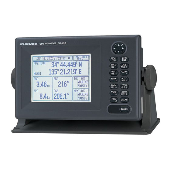
Marine GPS Navigator
GP-150
SOG
The future today with FURUNO's electronics technology.
R
FURUNO ELECTRIC CO., LTD.
9-52 Ashihara-cho, Nishinomiya City, Japan Phone: +81 (0)798 65-2111
Fax: +81 (0)798 65-4200, 66-4622 URL: www.furuno.co.jp
34 44
POSITION
135 21
WGS84
RNG
3.46
nm
SOG
8.4
k t
34 44.4
135 21.2
BRG
216
COG
Catalogue No. N-000
TRADE MARK REGISTERED
MARCA REGISTRADA
R
BRG
216
COG
206.
Advertisement
Chapters
Table of Contents
Troubleshooting

Related Manuals for Furuno GP-150


Summary of Contents for Furuno GP-150
- Page 1 34 44.449' N 135 21.219' E 206.1 Catalogue No. N-000 The future today with FURUNO's electronics technology. FURUNO ELECTRIC CO., LTD. 9-52 Ashihara-cho, Nishinomiya City, Japan Phone: +81 (0)798 65-2111 TRADE MARK REGISTERED Fax: +81 (0)798 65-4200, 66-4622 URL: www.furuno.co.jp...
- Page 2 Global Positioning System FURUNO GP-150 is a GPS navigator designed for the SOLAS ships according to the GPS performance standard IMO Res MSC.112(73) and associated IEC standards effective on and after July 1, 2003. It is a highly reliable standalone EPFS (electronic position fixing system) that feeds positioning information to AIS, Radar, VDR, VideoPlotter, Autopilot, Echo Sounder and Sonar.
- Page 3 n for SOLAS carriage requirements as a device and as a sensor for AIS, Radar, VDR, etc. Fully meets new IMO Resolution MSC.112(73) and IEC 61108-1 Ed.2 for SOLAS carriage requirements on and after 1 July 2003 Ideal sensor of SOG and COG for AIS, radars, and other navigational aids Augmentation to enhance accuracy by standard fitted WAAS and optional DGPS Display modes: VideoPlotter, 3-D Highway,...
-
Page 4: Interconnection Diagram
Fax: +45 36 77 45 01 Fax: +358 9 4355 6710 Fax: +7 812 766 55 52 FURUNO FRANCE S.A. FURUNO NORGE A/S FURUNO POLSKA Sp. Z o.o. Bordeaux-Mérignac, France Ålesund, Norway Gdynia, Poland Phone: +33 5 56 13 48 00... -
Page 5: Table Of Contents
INSTALLATION MANUAL GPS NAVIGATOR GP-150 1. SYSTEM CONFIGURATIONS ................1 2. EQUIPMENT LIST.................... 2 3. DISPLAY UNIT ....................4 4. ANTENNA UNIT ....................6 5. WIRING ......................10 6. INITIAL SETTINGS ..................12 7. OPTIONAL DGPS ................... 23 PACKING LISTS & INSTALLATION MATERIALS........... A-1 OUTLINE DRAWINGS .................. -
Page 7: Safety Instructions
SAFETY INSTRUCTIONS CAUTION WARNING Do not work inside the Ground the display unit to equipment unless totally prevent loss of sensitivity familiar with electrical and mutual interference. circuits. Confirm that the power supply voltage Hazardous voltage which can is compatible with the voltage rating cause electrical shock, burn of the equipment. - Page 8 This page is intentionally left blank.
-
Page 9: System Configurations
SYSTEM CONFIGURATIONS Antenna Unit GPA-018S* Antenna Unit GPA-019S* Antenna Unit GPA-017S** Radar, Echosounder, Autopilot etc. Display Unit DGPS Beacon Receiver 12-24VDC GR-80** *: w/internal beacon receiver **: w/o internal beacon receiver... -
Page 10: Equipment List
EQUIPMENT LISTS Standards Name Type Q'ty Remarks GPA-017S Antenna Unit GPA-018S For DGPS GPA-019S GP-150-E-N Without Beacon RX Display Unit GP-150-E-A With Beacon RX Installation CP20-01900 With Antenna Cable 1 set See lists Materials Without Antenna Cable CP20-01950 at end of... - Page 11 2. EQUIPMENT LISTS (Continued from the previous page) OP20-32-1 000-041-018 With GPA-018S OP20-32 000-041-019 With whip antenna and OP20-32-1 Beacon Receiver Set OP20-33 000-041-596 With GPS-019S OP20-34 000-041-598 Without whip antenna 000-013-485 For 100VAC mains Rectifier PR-62 000-013-486 For 220VAC mains DGPS Beacon Receiver GR-80 Whip Antenna...
-
Page 12: Display Unit
DISPLAY UNIT The display unit can be installed with either of four methods as shown below. Refer to the outline drawing at the end of manual. • Locate the unit away from exhaust pipes and vents. • The mounting location should be well ventilated. •... - Page 13 3. DISPLAY UNIT Flush mounting type S An optional flush mount kit type S is required. (Name: Flush Mount Kit S, Type: OP20-24, Code No.: 004-393-000) Name Type Code No. Wing bolt M4X30 YBSC2 000-804-799 Hex. bolt M6X12 SUS304 000-862-127 Wing nut M4 YBCS2 000-863-306...
-
Page 14: Antenna Unit
ANTENNA UNIT Mounting Install the antenna unit referring to the installation diagram at end of manual. When selecting a mounting location for the antenna unit, keep in mind the following points. • Select a location out of the radar beam. The radar beam will obstruct or prevent reception of the GPS satellite signal. - Page 15 4. ANTENNA UNIT Taping antenna unit GPA-018S After inserting the whip antenna to the antenna base of GPA-018S, tape the antenna base and whip antenna with self-vulcanizing tape and vinyl tape to reinforce the whip antenna. 1. Wrap the antenna junction point with butyl rubber tape No.15 (NITTO SINKO COOP.) or the equivalent.
- Page 16 4. ANTENNA UNIT Extending Antenna Cable Length The standard cable is 15m long. 30m and 50m long extension cable sets are optionally available. Extension cable line-up Fabricate the end of antenna cable and attach the coaxial connector. Details are shown on next page.
- Page 17 4. ANTENNA UNIT How to attach the N-P-8DFB connector Outer Sheath Armor Inner Sheath Shield Remove outer sheath and armor by the dimensions shown left. Expose inner sheath and shield by the dimensions shown left. Cover with heat-shrink tubing and heat. Cut off insulator and core by 10mm.
-
Page 18: Wiring
WIRING The figure below shows the connection of cables on rear of display unit. CAUTION Ground the display unit to prevent loss of sensitivity and mutual interference. Antenna Unit GPA-019S GPA-018S GPA-017S 20cm Rear of Display Unit Ground terminal DATA1 Ground Flat washer Crimp-on lug... - Page 19 5. WIRING Grounding The display unit contains several CPUs. While they are operating, they radiate noise, which can interfere with other radio equipment. Ground the unit as follows to prevent it. • The grounding wire should be 1.25sq or larger. •...
-
Page 20: Initial Settings
The default setting is "manual". Automatic DGPS setup GP-150 can automatically select optimum reference station. If it takes more than five (5) minutes to fix DGPS position at the automatic mode, switch to manual mode. Use the manual mode when an external beacon receiver has no automatic function of station selection. - Page 21 6. INITIAL SETTINGS 5. Press the NU/CU ENT key. 6. Press the MENU ESC key. Manual DGPS setup Enter frequency and baud rate of station. 1. Press MENU ESC, 9 and 7 to display the WAAS/DGPS SETUP menu. 2. Press to select MODE and press to select INT BEACON.
- Page 22 You can convert a Loran Plotter to a GPS Plotter with position data from the GP-150. Before selecting data to output, confirm what data the external equipment requires. Output necessary data only.
- Page 23 6. INITIAL SETTINGS Data format and data output availability Output data sentence of IEC 61162-1 and NMEA 0183 Ver. 1.5/2.0. AAM: Waypoint arrival alarm APB: Autopilot sentence B magnitude of cross track error, direction to steer, arrival alarm, bearing to waypoint ("Heading to steer to destination waypoint data"...
- Page 24 DPT: Depth HDG: Heading, deviation and variation HDM: Heading, magnetic HDT: Heading, true MTW: Water temperature TLL: Target latitude and longitude VBW: Dual ground/water speed VHW: Water speed and heading. FURUNO proprietary sentence AGFPA: Autopilot information from FURUNO autopilot equipments.
-
Page 25: General Data
TX rate of operation becomes small. Note 2: When the external equipment cannot display correct data input from the GP-150, the rate of operation should be lowered. For example, set a rate of operation less... - Page 26 6. INITIAL SETTINGS DATA 1 output setting 1) Press MENU ESC, 9 and 3. The DATA 1, 3 OUTPUT SETUP menu appears. DATA 1, 3 OUTPUT SETUP Data Fmt. V1.5 V2.0 Talker ID Output Data (00-90 sec) 100% TX rate of operation 1.
- Page 27 6. INITIAL SETTINGS DATA 2 output setting 1) Press NU/CU MENU, 9 and 4. The DATA 2 OUTPUT SETUP menu appears. DATA2 OUTPUT SETUP Data Fmt. V1.5 V2.0 Talker ID Output Data (00-90 sec) 100% 1. AAM:00 APA:00 APB:04 BOD:00 2.
- Page 28 6. INITIAL SETTINGS Setting DATA 4 to Data Output 1) Press MENU ESC, 9 and 5. The DATA 4 I/O SETUP menu appears. DATA 4 I/O SETUP DATA 4. Level RS232C RS422 Data Com. DGPS To Next Page : Select ENT : Enter MENU : Escape Appears only when external...
- Page 29 6. INITIAL SETTINGS Setting DATA 4 to “COM.” (general data) Waypoints and Routes data can be received from a personal computer, through the DATA 4 port. 1) Press MENU ESC, 9 and 5. 2) Press to select DATA4. Level. 3) Press to select level of personal computer;...
- Page 30 Setting DATA 4 to DGPS An external DGPS receiver can be connected to the DATA 4 port. Follow the procedure below to setup the GP-150 according to the specifications of the DGPS receiver. 1) Press MENU ESC, 9 and 5.
-
Page 31: Optional Dgps
RD-B TD-B Preamp unit (with 15 m cable) * This connection is required for L/L Auto mode of GR-80. When the GP-150 is connected with Beacon Receiver GR-80, do the setting as follows. Signal level RS-422 *1 First Bit Parity... - Page 36 Antenna Cable Set CP20-01700 (004-372-110) CP20-01710 (004-372-120)
- Page 37 Antenna Cable Set CP20-02700 (004-381-160) CP20-02710 (004-381-170)
- Page 43 Feb. 19, '03...
- Page 44 Feb. 19, '03...
- Page 48 *00015801600* *00015801600* *00015801600* *00015801600* ( ( YOSH YOSH ) ) GP-150 GP-150 * 0 0 0 1 5 8 0 1 6 0 0 * * 0 0 0 1 5 8 0 1 6 0 0 * *IME44400A10* *IME44400A10*...
-
Page 49: Shifting The Display
GPS NAVIGATOR GP-150/DUAL Operator’s Guide The purpose of this Guide is to provide basic operating procedures for this equipment. For more detailed information, see the Operator's Manual. Enlarging/Shrinking the Selecting a Display Mode Display Press DISPLAY SEL to select desired mode. - Page 50 9) Choose “ENTER” and press NU/CU ENT. Selecting Mark Shape/Line 10)Press NU/CU ENT. Type 1) Press MENU ESC and 2. Registering Routes 2) Press ▲ or ▼ to select Mark Shape (or Mark Line). 1) Press WPT RTE. 3) Press ◄ or ► to select mark shape (or 2) Press 6 (5 for Dual) to select Route mark line) desired.
- Page 51 GPS NAVIGATOR GP-150...
- Page 52 *00015801400* *00015801400* *00015801400* *00015801400* ( ( HIMA HIMA ) ) GP-150 GP-150 * 0 0 0 1 5 8 0 1 4 0 0 * * 0 0 0 1 5 8 0 1 4 0 0 * *OME44400A00* *OME44400A00*...
- Page 53 The screen you see depends on your system configuration and equipment settings. • FURUNO will assume no responsibility for the damage caused by improper use or modification of the equipment by an unauthorized agent or a third party.
- Page 54 SAFETY INSTRUCTIONS CAUTION WARNING Use the correct fuse. Do not open the cover of the equipment. Use of the wrong fuse can cause fire or equipment damage. This equipment uses high voltage electricity which can No single navigation aid (including this shock, burn or cause death.
- Page 55 5.4 Finding Range and Bearing Between TABLE OF Two Points........5-7 CONTENTS 6. SETTING UP VARIOUS DISPLAYS 6.1 Selecting Data to Display on the Data Display ........6-1 6.2 Selecting Position Format ..... 6-2 6.3 Demo Display ......... 6-4 FOREWORD ..........iv 7.
-
Page 56: Foreword
The main features of the GP-150 are FOREWORD • Comprehensive navigation data displays • Storage for 999 waypoints and 30 routes A Word to GP-150 Owners • Alarms: Waypoint Arrival, Anchor Watch, Congratulations on your choice of the Cross-track Error, Ship's Speed, Water FURUNO GP-150 GPS Navigator. -
Page 57: System Configuration
SYSTEM CONFIGURATION Antenna Unit GPA-018S* Antenna Unit GPA-019S* Antenna Unit GPA-017S** Radar, Echosounder, Autopilot etc. Display Unit DGPS Beacon Receiver 12-24VDC GR-80** *: w/internal beacon receiver **: w/o internal beacon receiver CATEGORY OF UNITS Unit Category ANTENNA UNIT Exposed to weather DISPLAY UNIT Protected from weather... - Page 58 This page intentionally left blank.
-
Page 59: Operational Overview
1. OPERATIONAL OVERVIEW 1.1 Control Description Cursor pads Shift display and cursor. MENU NU/CU Opens/closes menu; Selects display orientation; quits current operation. registers selections on menus. EVENT DISPLAY Inscribes event mark at Selects display mode. ship’s position; marks man overboard position GOTO Sets destination. -
Page 60: Turning On And Off The Power
When turning on the power the following Turning On and Off the occurs: Power The GP-150 takes about 90 seconds to find 12 seconds after turning on the power, position when turned on for the very first time. accurate position (in latitude and longitude) Thereafter it takes about 12 seconds to find appears on the display. -
Page 61: Adjusting Display Contrast And Brilliance
1. OPERATION Adjusting Display Selecting the Display Contrast and Brilliance Mode 1) Press the TONE key. The display shown 1) Press the DISPLAY SEL key. The display in Figure 1-3 appears. shown in Figure 1-4 appears. Select Display Plotter 1 Plotter 1 Plotter 2 Tone:... -
Page 62: Highway Display
1. OPERATION Plotter 1 display Plotter 2 display Cursor position data, Bearing from own ship when cursor is on Ship's position appears when cursor is off to destination waypoint RAIM Course GPS receiving Own ship's reliability* condition track Own ship Alarm Distance for D3D 100m... - Page 63 1. OPERATION 2) With autopilot connection, automatic Navigation display mode 1) No autopilot connection 100m Cross track SAFE Bearing from own error meter ship to destination 12.3 waypoint Bearing Destination Speed over ground scale Velocity To waypoint no. Destination BRG: 10.3 63°...
-
Page 64: Icons
1. OPERATION Data display Refer to Chapter 6 for user-defined window setting. The ZOOM icon can be displayed by pressing the CURSOR ON/OFF key. Position in latitude and longitude or LOPs U: UTC Fixing date and time* J: JST Zoom icon S: Ship's time 100m SEP 12, 2005 23:59'59"... -
Page 65: Track
Shifting the Cursor 2. TRACK The cursor can be shifted with the cursor pads. 1) Press the CURSOR ON/OFF key to turn Enlarging/Shrinking the on the cursor. Display 2) Press the cursor pads. You may enlarge and shrink the display on The cursor moves in the direction of the the Plotter 1, Plotter 2 and Highway displays, cursor pads pressed. -
Page 66: Shifting The Display
Plotting and Recording of Track Shifting the Display The GP-150 stores 2,000 points of track and The display can be shifted on the Plotter 1 marks. When the memory becomes full the and Plotter 2 displays, with the CURSOR oldest track is erased to make room for the ON/OFF key. -
Page 67: Erasing Track
2. TRACK Hold icon Erasing Track (appears while recording of track is stopped) The track stored in the memory and displayed on the screen can be erased. D3D 100m 34° 23.456· N 135° 45.678· E SAFE CAUTION 234° Track cannot be restored once erased. Be absolutely sure you want to erase all track. -
Page 68: Selecting Track Plotting Interval
2. TRACK 3) Press to select Track Rec. Are you sure to erase ? 4) Press to select Time. 5) Enter plotting interval in four digits. To enter 30 seconds, for example, press 0, ENT: Yes MENU: No 0, 3, 0. Figure 2-6 Prompt for erasure 6) Press the NU/CU ENT key. -
Page 69: Apportioning The Memory
2. TRACK 3) Press 1 to display the PLOTTER SETUP 2.10 Apportioning the menu. Memory PLOTTER SETUP The memory holds 2,000 points of track and Trk = 1000 / 2000Pt Memory Apportion marks and may be apportioned as you like. Bearing Ref. -
Page 70: Selecting Bearing Reference
2. TRACK 2.11 Selecting Bearing Entering magnetic variation Reference The location of the magnetic north pole is different from the geographical north pole. Ship's course and bearing to waypoint may This causes a difference between the true be displayed in true or magnetic bearing. and magnetic north direction. -
Page 71: Marks
Erasing marks 3. MARKS CAUTION Entering/Erasing Marks All marks, including event marks and the Marks can be inscribed on the Plotter 1 and MOB mark, are erased on the ERASE MARK menu. Be absolutely sure you want Plotter 2 displays. You may inscribe a mark to erase all marks;... -
Page 72: Selecting Mark Shape
Selecting Mark Shape Connecting Marks (selecting mark connection 13 mark shapes are available. Select mark shape as follows: line) Marks can be connected with lines. Three 1) Press MENU ESC and 2 to display the types of connection lines are available and TRACK/MARK SETUP menu. -
Page 73: Entering Event Marks
3. MARKS Entering Event Marks Selecting Event Mark Shape Event marks can denote any important present position. Event marks can be saved Event marks are available in 10 shapes. as ordinary marks and the unit automatically Select event mark shape as follows. numbers them from 01 to 99. -
Page 74: Entering The Mob Mark
2) Press the NU/CU ENT key. If the display Entering the MOB Mark in use is Highway, Navigation or Data, The MOB mark denotes man overboard they are automatically replaced by the position. To mark man overboard position, Plotter display. press the EVENT MOB key more than three seconds. -
Page 75: Navigation Planning
Waypoints are automatically given the The GP-150 can store 999 waypoints, youngest empty waypoint number and numbered from 001-999. Waypoints can be this number appears on the third line. - Page 76 4. NAVIGATION PLANNING 10) Press the NU/CU ENT key. 6) Press to select waypoint mark shape. Control is returned to the last used The following display appears. display mode. When the waypoint number entered at step 5 already exists, the message : Cursor shown in Figure 4-4 appears if the ENT: Enter...
- Page 77 4. NAVIGATION PLANNING Registering waypoints by MOB Registering waypoints by own ship's position/event position position The MOB position or an event position can Note: When there is no position data, you be registered as a waypoint. Event marks cannot register a waypoint at own ship's are numbered from 01 to 99;...
- Page 78 4. NAVIGATION PLANNING Note: Alternatively, you may enter position, WAYPOINT LIST (L/L) leaving the waypoint number blank. 34° 12.345’ N 130° 23.456’ W 4) Enter range and bearing you wish to use MARINE POINT AUG 12’ 95 12 : 35U to calculate position of new waypoint.
-
Page 79: 4.2 Editing Waypoints
4. NAVIGATION PLANNING 4.2 Editing Waypoints Deleting Waypoints 1) Press WPT RTE and 5. Deleting waypoints by the cursor 2) Press to select waypoint to 1) Place the cursor on the waypoint to edit. delete. 3) Press 2) Press the CLEAR key. 4) Edit the contents of the waypoint. -
Page 80: Registering Routes
ENT: Enter MENU: Escape destination waypoint repeatedly. Use: In use Fwd: Traverse waypoints in forward order The GP-150 can store 30 routes and each Rvs: Traverse waypoints in reverse order route may contain up to 30 waypoints. Figure 4-15 Route editing screen Routes can be registered while in the Plotter 1 or Plotter 2 display mode. -
Page 81: Deleting Route Waypoints
4. NAVIGATION PLANNING Using previously registered waypoints Replacing Route Enter waypoints in the order they will be Waypoints traversed; not by waypoint number order. 1) Press WPT RTE and 6 to display the . The reverse video on the 7) Press route list. -
Page 82: Deleting Routes
4. NAVIGATION PLANNING Deleting Routes 1) Press WPT RTE and 6 to display the route list. 2) Press to select route to delete. 3) Press the CLEAR key. The display shown in Figure 4-17 appears if the route is in use. 1st line Are you sure to erase ? ENT: Yes... -
Page 83: Starting For Destination
A dashed consisting of 30 points. When all 30 points line connects own ship and the are entered, the GP-150 automatically destination, which is marked with a flag, disables further entry. as shown in Figure 5-4. - Page 84 5. STARTING FOR DESTINATION Flag mark Overwriting ? ENT:Yes MENU:No Figure 5-6 8) Press the NU/CU ENT key. The waypoints do not have waypoint Figure 5-4 Single destination set by cursor numbers, however you can attach waypoint numbers by doing the following. Setting multiple destinations Press WPT RTE and 6 to display the 1) Press GOTO and 1.
- Page 85 5. STARTING FOR DESTINATION Setting destination by MOB position or Setting destination through waypoint event position list Note: This operation cannot be performed when there is no MOB position or Note: A waypoint must exist to set it as event position. The buzzer sounds destination.
- Page 86 5. STARTING FOR DESTINATION Setting destination by waypoint no. Route number can be entered here when this line appears in reverse video. 3) Enter waypoint number, in three digits. GOTO (Route List) FORWARD You can clear entry by pressing the Route No.
-
Page 87: 5.2 Canceling Destination
5. STARTING FOR DESTINATION 2) Press to select route waypoint Skipping route waypoints to skip. You may skip route waypoints by displaying 3) Press to shift the cursor to the "DI" (DIsable) next to the route waypoint in right of the waypoint number. the route list. -
Page 88: Erasing Route Waypoints (Flags)
5. STARTING FOR DESTINATION Erasing Route When flags are erased Waypoints (flags) When the origin waypoint is erased the waypoint before it becomes the origin 1) Place the cursor on the flag to erase. waypoint. If there is no waypoint before the 2) Press the CLEAR key. -
Page 89: Finding Range And Bearing Between Two Points
5. STARTING FOR DESTINATION 5.4 Finding Range and Calculation Procedure Bearing Between Two You can find the range and bearing between two points by two waypoints or two latitude Points and longitude positions. Selecting Course Sailing Method 1) Press MENU ESC and 5. The MANUAL The range and bearing to a destination are CALCULATION menu appears. - Page 90 5. STARTING FOR DESTINATION 4) Press to shift the cursor to the Trial Speed line. 5) Press to select Auto or Man. Auto uses ship's average speed to calculate time-to-go. 6) If you selected Man, enter speed. 7) Press the NU/CU ENT key. The range, bearing and time-to-go between two points appear on the display.
-
Page 91: Setting Up Various Displays
• Speed thru water (STW) 6. SETTING UP • Time-to-go to waypoint (TTG) • ETA to route VARIOUS • Total route distance (RT.DIST)* • Trip distance (TRIP) DISPLAYS • Trip elapsed time (TRIP TM) • Water temperature (W.TMP)#, and • Velocity to destination (VTD)* Selecting Data to Display *ALT: Displayed only in 3D position fixing. -
Page 92: Selecting Position Format
6. SETTING UP VARIOUS DISPLAYS Selecting Position Format For Loran LOPs 6) Press to select LC Chain. Position can be displayed in latitude and 7) Key in GRI code referring to the Loran C longitude, Loran C LOPs, or Decca LOPs, chain list appears in the Appendix. - Page 93 6. SETTING UP VARIOUS DISPLAYS 5) Key in LOP1 and LOP2, to enable Registering waypoints using LOPs calculation. 1) Press WPT RTE and 5. 6) Press to calculate LOPs. "Calculating" 2) Press to display LOPs. appears between parentheses during the calculation.
-
Page 94: 6.3 Demo Display
6. SETTING UP VARIOUS DISPLAYS 6.3 Demo Display Note: When the memory is cleared while in the demonstration mode, the The demo display provides simulated equipment starts up in the normal operation of this unit. Own ship tracks, at the mode. -
Page 95: Alarms
1) Press the MENU ESC key. 7. ALARMS 2) Press 4 to display the ALARM SETTINGS menu. ALARM SETTINGS There are seven alarm conditions which Arrival/Anchor Arr. Anc. generate both audible and visual alarms. Alarm Range 0.100nm When an alarm setting is violated, the buzzer Alarm Range 0.050nm sounds and the name of the offending alarm... -
Page 96: Cross Track Error (Xte) Alarm
7. ALARMS Anchor watch alarm Cross Track Error (XTE) The anchor watch alarm sounds to warn you Alarm that own ship is moving when it should be at The XTE alarm warns you when own ship is rest. off its intended course. Alarm Own ship’s setting... -
Page 97: Ship's Speed Alarm
7. ALARMS Ship’s Speed Alarm Trip Alarm The ship’s speed alarm sounds when ship's The trip alarm sounds when the distance run speed is lower or higher (or within) the alarm is greater than the trip alarm setting. range set. 1) Press MENU ESC and 4. -
Page 98: Water Temperature Alarm
7. ALARMS Water Temperature Depth Alarm Alarm The depth temperature alarm sounds when the depth is higher or lower (or within) the The water temperature alarm sounds when preset depth. This alarm requires video the water temperature is higher or lower (or sounder connection. -
Page 99: Menu Settings
UNSAFE: GPS signal is abnormal, therefore smoothed the raw data, however too high a the positioning accuracy is not reliable. Note setting slows response time to change in that the GP-150 does not exclude abnormal latitude and longitude. This is especially signals automatically. - Page 100 8. MENU SETTINGS Geodetic datum Selecting fix mode Select the geodetic chart system you are 1) Press MENU ESC, 9 and 6 to display the using. WGS-84 (standard GPS chart system) GPS SETUP menu. and NAD 27 can be directly selected. For GPS SETUP other charts, select "OTHER"...
- Page 101 8. MENU SETTINGS 4) Press the NU/CU ENT key. Entering GPS speed smoothing Press the MENU ESC key. 1) Press MENU ESC, 9 and 6. 2) Press to select Spd. Entering geodetic datum 3) Enter smoothing factor in three digits (0000-9999).
-
Page 102: Selecting Units Of Measurement
8. MENU SETTINGS Entering position Unit of depth After the unit is installed you may enter 1) Press MENU ESC, 9 and 2. position to shorten the time it takes to find 2) Press to select Unit of Depth. position. (It takes about two minutes when 3) Press to select unit;... -
Page 103: Mark, Character Size And Brilliance
8. MENU SETTINGS Mark, Character Size Waypoint mark size and Brilliance The size of the waypoint mark can be selected to large or small. The DISPLAY SETUP menu lets you select the size and brilliance of various markers. Large waypoint mark No icon With icon Grid tone... -
Page 104: Settings For Connection Of Navigator
Besides its fundamental function of Data display. displaying position, the GP-150 can also 1) On the Data display, with no enlarged output various data to external equipment. characters, press the CURSOR ON/OFF Before outputting data to external equipment, key to turn on the zoom icon. - Page 105 DATA 1 is output from DATA 3. When the external equipment cannot display For log pulse, select 200 or 400 pulse per correct data input from the GP-150, the rate second depending on the device connected. of operation should be lowered.
-
Page 106: Receiving Data From Personal Computer
8. MENU SETTINGS Setting DATA 4 to NMEA Receiving Data from Personal Computer The DATA 4 port connects to a personal computer, DGPS receiver or YEOMAN Loading Waypoints/Routes data equipment. Waypoints and Routes data can be downloaded from a personal computer, 1) Press MENU ESC, 9 and 5. - Page 107 8. MENU SETTINGS 2) To quit loading, press the NU/CU ENT 13) Press the NU/CU ENT key. The message key. The cursor shifts to Stop. shown in Figure 8-14 appears while data 3) To start loading, select Start. is being loaded. 4) Press the NU/CU ENT key.
-
Page 108: Waas/Dgps Settings
8. MENU SETTINGS 12) Save data at the computer. Loading completed 13) Press the MENU ESC key. When data is Valid waypoint saved, the cursor shifts to Stop. Invalid waypoint : 0 14) Press the MENU ESC key. Press any key Figure 8-21 WAAS/DGPS Setting 8) Press the [MENU ESC] key twice. - Page 109 When an external DGPS beacon receiver is connected to the DATA 4 connector, set up the GP-150 according to specification of DPGS beacon receiver connected as follows. 1) Press MENU ESC, 9 and 5. 2) Press to select Level.
-
Page 110: Displaying Gps Monitor Displays
8. MENU SETTINGS DATA 4 I/O SETUP "DGPS" Number, bearing and elevation angle of all satellites in view of the GPS receiver appear. Satellites being To Previous Page used in fixing position are circled with a solid line; satellites not being used in fixing position are circled First Bit with a dashed line. -
Page 111: Maintenance & Troubleshooting
3) Press to select Yes. The following message appears. Clearing the Memory Setting for cold start Are you sure to clear ? The GP-150 has two memories: GPS ENT:Yes MENU:No memory and plotter memory. Clearing the plotter memory Figure 9-3 The plotter memory holds plotted track and 4) Press the NU/CU ENT key. -
Page 112: Preventive Maintenance
9. MAINTENANCE & TROUBLESHOOTING Preventive Maintenance Error Messages Regular maintenance is necessary to Error messages appear on the display to maintain performance. Check the items alert you to possible trouble. mentioned below monthly to keep the WARNING equipment in good working order. Do not open the display unit cover. - Page 113 9. MAINTENANCE & TROUBLESHOOTING Press the CLEAR key to silence the buzzer. If the CLEAR key is not pressed, several beeps sound every three minutes. DGPS error When DGPS data contains errors or the DGPS beacon station is experiencing transmitting problems, the message shown in Figure 9-7 appears.
-
Page 114: Troubleshooting
• Tx interval may be set to “0”. Select proper interval. MENU ESC, 9-3, 9-4, 9-5 See the installation manual for further details. • Check appropriate settings on external equipment. • Check connections: GP-150 external equipment TD-A RD-A TD-B RD-B... -
Page 115: Diagnostic Tests
9. MAINTENANCE & TROUBLESHOOTING OK appears to the right of GPS and Diagnostic Tests BEACON when they are normal; NG and Memory and I/O circuits test 16 hexadecimal figure appear when an 1) Press MENU ESC and 8 to display the abnormality is found. - Page 116 9. MAINTENANCE & TROUBLESHOOTING Display test Automatic testing 1) Press MENU ESC, 8 and 3 to display the This feature conducts all self tests test pattern screens. continuously. 1) Press MENU ESC, 8 and 4. Self tests are 2) To change the test pattern, press the NU/CU ENT key.
-
Page 117: Menu Tree
MENU TREE Main menu MENU 1. DISPLAY SETUP Grid (Dark, Light, Off) Course Bar (Dark, Light, Off) Time Mark (Dark, Light, Off) Waypoint Size (Large, Small) Cursor Size (Large, Small) Set/Drift Ave (Off, 10min, 20min, 30min, 1hour, 2hour, 3hour, 5hour, 6 hour) 2. - Page 118 APPENDIX 9. SYSTEM SETTINGS 1. PLOTTER SETUP Memory Apportion (Trk: 1000/2000 Pt) Bearing Ref. (True, Mag) Mag Variation (Auto, Man) (07°W) (00°E) Calculation (RL, GC) SOG, COG, RNG, BRG, User defined #1 W. TMP, W. DPT, XTE, dCOG, AVR SOG, AVR COG, TTG, ETA, TRIP, TRIP TM, RT.
- Page 119 APPENDIX 6. GPS SETUP Fix Mode (2D, 2/3D) ANT Height (016 ft, 000 - 999 ft) Disable Satellite (1 - 32) GPS Smoothing Posn (0000, 0000 - 9999 sec) Spd (0005, 0000 - 9999 sec) Speed Average (0060, 0000 - 9999 sec) RAIM Function (Off, On) RAIM Accuracy (100, 1 - 999) Geodetic Datum (WGS84, NAD27, OTHER)
-
Page 120: Digital Interface (Iec 61162-1 Edition 2 (2000-07
Isolation: Optocoupler Input impedance: 470 ohms Max. voltage: ±15V Threshold: 3 mA (in case of connection of FURUNO device talker) Data transmission Data is transmitted in serial asynchronous form in accordance with the standard referenced in 2.1 of IEC 61162-1. The first bit is a start bit and is followed by data bits. - Page 121 DATA 1 port (input) 20P8192 DATA 1 MJ-A6SRMD +3.3V R130 2.2K RD-H PC-400 R182 R123 RD-C CR15 1SS272 • Load Requirements Isolation: opto coupler Input Impedance: 470 Ω Max. Voltage: ± Threshold: 3mA (In case of FURUNO device talker connection) AP-5...
- Page 122 DATA 2 port (input) 20P8192 DATA2 MJ-A6SRMD +3.3V R131 FL10 2.2K RD-H PC-400 R183 R124 RD-C CR15 FL11 1SS272 • Load Requirements Isolation: opto coupler Input Impedance: 470 Ω Max. Voltage: ± Threshold: 3mA (In case of FURUNO device talker connection) AP-6...
- Page 123 APPENDIX DATA 3 port (output) Output drive capability: Max. 15mA 20P8192 DATA3 MJ-A6SRMD SN75ALS172 FL15 TD-A TD-B FL14 DATA 4 port IN/OUT signal is selected by the menu among the output of IEC 61162-1, NMEA Ver. 1.5/2.0, PC input/output and DGPS signal. Sentence description AAM-Waypoint arrival alarm $--AAM,A,A,x.x,N,c--c*hh<CR><LF>...
- Page 124 APPENDIX APB - Autopilot sentence data $--APB,A,A,x.x,a,N,A,A,x.x,a,c--c,x.x,a,x.x,a,a*hh<CR><LF> | | | | | | | | | | | | | | | | | | | +------- 13 | | | | | | | | +--------- 12 | | | | | | | | +--+----------- 11 | | |...
- Page 125 APPENDIX BOD - Bearing, origin to destination $--BOD,x.x,T,x.x,M,c--c,c--c*hh<CR><LF> | +--------- 5 +------------ 4 +----------------- 3 | +--+--------------------- 2 +--+--------------------------- 1 1. Bearing, degrees true 2. Bearing, degrees magnetic 3. Destination waypoint ID 4. Origin waypoint ID 5. Checksum BWC - Bearing and distance to waypoint $--BWC, hhmmss.ss, llll.ll, a yyyyy.yy, a, x.x, T, x.x, M, x.x, N, c--c, a*hh<CR><LF>...
- Page 126 APPENDIX BWR - Bearing, waypoint to range $--BWR,hhmmss.ss,llll.lll,a,yyyyy.yyy,a,x.x,T,x.x,M,x.x,N,c--c,a*hh<CR><LF> | +---- 9 | +------ 8 | +--------- 7 | +--+------------- 6 | +--+------------------- 5 | +--+------------------------- 4 +-----+------------------------------- 3 +-----+------------------------------------------- 2 +---------------------------------------------------------- 1 1. UTC of observation 2. Waypoint latitude, N/S 3.
- Page 127 APPENDIX DBT - Depth below transducer $--DBT, x. x, f, x. x, M, x. x, F*hh<CR><LF> 1. Water depth, feet 2. Water depth, m 3. Water depth, fathoms 4. Checksum DPT - Depth $--DPT,x.x,x.x,x.x*hh<CR><LF> | +----- 4 +--------- 3 +------------ 2 +---------------- 1 1.
- Page 128 APPENDIX DTM - Datum reference $--DTM,ccc,a,x.x,a,x.x,a,x.x,ccc*hh<CR><LF> | | | | | | | +--- 7 | | | +------ 6 | | | | +---------- 5 | | | | +--+------------- 4 | | +---+------------------- 3 | +------------------------- 2 +---------------------------- 1 1.
- Page 129 APPENDIX GGA -Global positioning system fix data $--GGA,hhmmss.ss,llll.lll,a,yyyyy.yyy,a,x,xx,x.x,x.x,M,x.x,M,x.x,xxxx*hh<CR><LF> | | | | | | +-- 11 | | | +---- 10 | | | | +--------- 9 | | | | +---+------------ 8 | | | +---+------------------ 7 | | | +------------------------- 6 | | +---------------------------- 5 | +------------------------------- 4...
- Page 130 APPENDIX GNS - GNSS fixed data $--GNS,hhmmss.ss,llll.lll,a,yyyyy.yyy,a,c--c,xx,x.x,x.x,x.x,x.x,x.x*hh<CR><LF> +--- 11 +------ 10 +---------- 9 +-------------- 8 +------------------ 7 | +---------------------- 6 +------------------------- 5 | +------------------------------ 4 +-------+--------------------------------- 3 +---+--------------------------------------------- 2 +------------------------------------------------------------- 1 1. UTC of position 2. Latitude, N/S 3. Longitude, E/W 4.
- Page 131 APPENDIX RMB - Recommended minimum navigation information $--RMB,A,x.x,a,c--c,c--c,llll.lll,a,yyyyy.yyy,a,x.x,x.x,x.x,A,a*hh<CR><LF> | | | | | +--- 13 | +----- 12 | +------- 11 | +---------- 10 +-------------- 9 | +------------------ 8 +-----+--------------------- 7 +----+--------------------------------- 6 +--------------------------------------------- 5 | | +-------------------------------------------------- 4 | +------------------------------------------------------ 3 | +--------------------------------------------------------- 2 +------------------------------------------------------------ 1 1.
- Page 132 APPENDIX RMC- Recommended minimum specific GPS/TRANSIT data $--RMC,hhmmss.ss,A,llll.lll,a,yyyyy.yyy,a,x.x,x.x,xxxxxx,x.x,a,a*hh<CR><LF> | | | | | | | +--- 10 | | +----- 9 +--+------- 8 +--------------- 7 | +--------------------- 6 | +------------------------- 5 +---+---------------------------- 4 +---+---------------------------------------- 3 +--------------------------------------------------- 2 +---------------------------------------------------------- 1 1. UTC of position fix 2.
- Page 133 APPENDIX TLL - Target latitude and longitude $--TLL,xx,llll.lll,a,yyyyy.yyy,a,c--c,hhmmss.ss,a,a*hh<CR><LF> | | | | | +--------- 8 | +----------- 7 +------------- 6 +-------------------- 5 | +-------------------------- 4 +-----+------------------------------ 3 | +----+------------------------------------------ 2 +----------------------------------------------------- 1 1. Target number 00 - 99 2. Latitude, N/S 3.
- Page 134 APPENDIX VDR – Set and drift $--VDR,x.x,T,x.x,M,x.x,N*hh<CR><LF> | | | | | +--------- 4 | +--+----------- 3 | | +--+----------------- 2 +--+----------------------- 1 1. Direction, degrees true 2. Direction, degrees magnetic 3. Current speed, knots 4. Checksum VHW – Water speed and heading $--VHW,x.x,T,x.x,M,x.x,N,x.x,K*hh<CR><LF>...
- Page 135 APPENDIX WCV - Waypoint closure velocity $--WCV,x.x,N,c--c,a*hh<CR><LF> | | | | | +------- 4 | +--------- 3 | +--+----------- 2 +--+---------------- 1 1. Velocity component, knots 2. Waypoint identifier 3. Mode indicator(see note) 4. Checksum NOTE Positioning system Mode indicator: A = Autonomous D = Differential S = Simulator...
- Page 136 APPENDIX XTE - Cross-track error, measured $--XTE,A,A,x.x,a,N,a*hh<CR><LF> | | | | | | | | | +--------- 7 | | | +----------- 6 | | +------------- 5 NOTE Positioning system Mode indicator: | +--------------- 4 A = Autonomous mode | | +------------------ 3 D = differential mode | +--------------------- 2 S = Simulator mode...
-
Page 137: Time Differences
TIME DIFFERENCES AP-21... -
Page 138: Geodetic Chart List
GEODETIC CHART LIST 001 : WGS84 088 : NORTH AMERICAN 1927 : Western United States 002 : WGS72 089 : : Eastern United States 003 : TOKYO : Mean Vallue (Japan, Korea, and Okinawa) 090 : : Alaska 004 : NORTH AMERICAN 1927 : Mean Vallue (CONUS) 091 : : Bahamas (Excluding San Saivador Island) -
Page 139: Loran C Chains
LORAN C CHAINS c i f – – – – – – – – – – – – – – – – – – – – – – – – – – – c i f – – – – c i f –... -
Page 140: Decca Chains
DECCA CHAINS c i t " " s i t " " " " a l l " s i t " " " " " " c i t " " " a i l " " s i l "... -
Page 141: Parts List
This equipment contains complex modules in which fault diagnosis and repair down to component level are not practical (IMO A.694(17)/8.3.1). Only some discrete components are used. FURUNO Electric Co., Ltd. believes identifying these components is of no value for shipboard maintenance; therefore, they are not listed in the manual. Major modules can be located on the parts location photos on the next page. -
Page 142: Parts Location
Parts Location Display unit GR-7000A (Option) (08S0334) GN-8096 (20S0395) NP Board (20P8192) PNL Board (20P8148) EW50379FDW Display unit, cover opened, GR-7000A installed A-26 A-34... -
Page 143: Specifications
FURUNO GP-150/Dual SPECIFICATIONS OF GPS NAVIGATOR GP-150/Dual GPS RECEIVER Receiving Frequency 1575.42 MHz Tracking Code C/A code Number of Channel GPS: 12 channels parallel, 12 satellites Position Fixing Method All-in-view, 8-state Kalman filter Accuracy GPS: 10 m approx. (2drms) DGPS: 5 m approx. - Page 144 GNS, RMB, RMC, Rnn, RTE, VTG, WCV, WNC, WNR, WPL, XTE, ZDA (or LOGOUT depending on jumper setting for Port 3), Waypoint data to conventional PC (DATA 4 only) * GP-150-Dual: DATA 2 port is used for the system connection. **: GP-150 only POWER SUPPLY Display Unit 12-24VDC: 0.8-0.4A (w/ internal beacon receiver)
-
Page 145: Index
INDEX Editing Waypoints 4-5 Anchor watch alarm 7-2 Entering marks 3-1 Apportioning the Memory 2-5 entry of comment 4-2 Arrival Alarm 7-1 Entering position 8-3 Automatic testing 9-6 Enlarging characters 8-5 Erasing Track 2-3 Erasing marks 3-1 brilliance 1-3 Erasing Route Waypoints 5-6 Error Messages 9-2 Event Marks 3-3 Canceling Destination 5-5... - Page 146 INDEX Magnetic variation 2-6 User-defined display 6-1 Mark Shape 3-2 Unit distance 8-3 mark connection line 3-2 Unit of depth 8-3 Memory and I/O circuits test 9-5 Unit of water temperature 8-4 MOB Mark 3-4 Unit of altitude 8-4 Plotter 1 display 1-4 Water Temperature Alarm 7-4 Plotter 2 display 1-4 Waypoint mark size 8-5...
-
Page 147: Declaration Of Conformity
• Test Reports No. FLI 12-03-014 of 12 June 2003, FLI 12-02-040 of 29 August 2003, FLI 12- 03-065 of 19 December 2003 and FLI 12-05-047 of 26 October 2005 prepared by Furuno Labotech International Co., Ltd., Nishinomiya, Japan This declaration is issued according to the provisions of European Council Directive 96/98/EC on marine equipment modified by the Commission Directive 2002/75/EC. - Page 148 For Internal Use Only Serial No. 4415 - Checked By: PACKING LIST FOR GP150 Tech Date Box 1 - GP150 Wt: 10 lbs. Dim: 10"x 17"x 8" GP150 Part No. Description Quantity Remarks GP150 IMO GPS Navigator 004-390-940 Mounting Bracket 100-173-274 Mounting Knob GPA017S...
- Page 149 Type designation: See Annex 3 Serial N See Annex 3 Software release N See Annex 3 Manufacturer: Furuno Electric Co., Ltd. Address: 9-52 Ashihara Cho City: 662-8580 Nishinomiya City Country: Japan complies with the international instruments and test standards as listed in the Annex.
- Page 150 A DGPS beacon receiver can be connected to this equipment or the DGPS beacon receiver board GR-7000A can be installed for DGPS operation of GP-150. GP-150 Dual is a system, which consists of two inter-working GPS Receivers, type GP-150, the interface unit, type IF-2500 and, if applicable, the GPS/beacon antenna distribution unit, type MD-GB2.
- Page 151 Display: monochrome System related equipment The product to which this certificate relates includes to following units or equipment: GP-150: GPS receiver with monochrome LCD GPA-017S: GPS antenna GPA-018S: combined GPS and whip antenna for beacon reception GPA-019S: combined GPS and ferrite loop antenna for beacon reception...
- Page 152 Trademark: Furuno Serial No: 4415-0011 Software release No: GPS: 48502640xx; NAV: 2051518-01.xx; Beacon 08501820xx Type designation: GP-150 DUAL Trademark: Furuno Serial No: 4415-0011; 4415-0022 Software release No: GPS: 48502640xx; NAV: 2051520-01.xx; Beacon 08501820xx Telefication, Edisonstraat 12A, 6902 PK Zevenaar, The Netherlands...
Need help?
Do you have a question about the GP-150 and is the answer not in the manual?
Questions and answers