Table of Contents
Advertisement
Advertisement
Table of Contents

Related Manuals for CAS PW-II


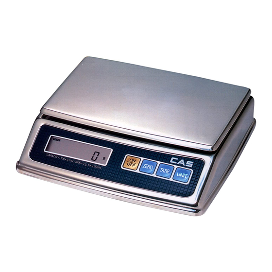
Summary of Contents for CAS PW-II
- Page 1 Service Manual PW-II PW-II SERVICE MANUAL...
-
Page 2: Table Of Contents
< Table of Contents > Introduction ..........................4 1.1. Preface ........................... 4 1.2. Precaution..........................4 1.3. Specifications........................5 1.3.1. PW-II Specifications ..................5 1.4. Key............................6 1.5. Sealing Method ......................... 7 Calibration ........................... 8 2.1. General Calibration......................8 2.1.1. C4 Setting ......................9 2.1.1.1. - Page 3 Service Manual PW-II Part Location..........................18 5.1. Main PCB (Front) ......................18 5.2. Main PCB (Rear) ......................19 5.3. Battery PCB ........................20 5.4. Key PCB ..........................201 Partlist ............................22 6.1. Circuit Part .................. 22 6.1.1. Main PCB Ass'y..............22 6.1.2.
-
Page 4: Introduction
1. Introduction 1.1. Preface Thank you for purchasing of our CAS scale. This scale has been designed with CAS reliability, under rigid quality control and with outstanding performance. WE hope that your departments enjoy with high quality of CAS product. -
Page 5: Specifications
Service Manual PW-II 1.3. Specifications 1.3.1. PW-II Specifications PW-II(2kg) PW-II(5kg) PW-II(10kg) Capacity / e 2,000g / 1 g 5,000g / 2 g 10,000g / 5 g (2 kg / 0.001 kg) (5 kg / 0.002 kg) (10 kg / 0.005 kg) 5 lb / 0.002 lb... -
Page 6: Key
Service Manual PW-II 1.4. Key Function HOLD To make the weight of item stable. This weight is average value. UNIT Used to convert the unit of weight TARE To input or cancel the tare (the weight of container). ZERO (-O-) -
Page 7: Sealing Method
Service Manual PW-II 1.5. Sealing Method... -
Page 8: Calibration
Service Manual PW-II 2. Calibration 2.1. General Calibration Pressing and holding calibration switch press [POWER] key to go to calibration mode. User can move to other mode by using [ZERO] key in the calibration mode. User also moves to other sub-modes for each mode by using [HOLD] and [TARE] key. -
Page 9: C4 Setting
10,000 0010 1XXX PW-II has four different weight units, g, kg, lb, or oz as shown in shaded area. You can set the capacity to input first 5 bits, for example, “00011” for 5 kg capacity. Next three (3) bits represent “Interval” information. For example, if you set 5 kg interval the Hexa value will be “0x18”. -
Page 10: C4-4 Setting
Service Manual PW-II 2.1.1.4. C4-4 Setting lb ROM Version Only UNIT CHANGE Comma Setting Buzzer Setting ENABLE 1XXX XXXX ENABLE XXX1 XXXX ENABLE XXXX 0XXX DISABLE 0XXX XXXX DISABLE XXX0 XXXX DISABLE XXXX 1XXX C4-4 is to set to use the unit change function and the displaying unit. -
Page 11: Gravity Constant Value Setting (C-9)
Service Manual PW-II 2.1.3. Gravity Constant Value Setting (C-9) Current gravitational Acceleration value is set to 9.7994 m/s (1) Pressing and holding “Calibration Switch” press [POWER] key. After “CAL” message blinks three times and shows the version of scale, it displays “C-0”... -
Page 12: How To Confirm Span Calibrated A/D Value (C-1)
Service Manual PW-II 2.1.5. How to confirm SPAN calibrated A/D value (C-1) Pressing and holding Calibration Switch please press [POWER] key. After “CAL” message blinks three times and the version of scale is displayed, “C-0” message will be displayed. Press [TARE] to change “C-0” to “C–1”. -
Page 13: Calibration Block Diagram
Service Manual PW-II 2.1.7. Calibration Block Diagram S T A R T 교 정 단 위 외 부 분 해 능 C - 4 C - 4 - 1 D is p la y U n it T A R E O p tio... -
Page 14: The Schematics And Diagram
PW-II Service Manual 3. The Schematics and Diagram 3.1. System Block Diagram EEPROM (24C02) POWER (DC 9V/300mA) Driver Load DISPLAY & Converter Cell (LCD) Filter (ADS1100) ( NEC 78Fseries) Battery_AA SIZE (1.5V x 6) -
Page 15: Circuit Diagram
PW-II Service Manual 3.2. Circuit Diagram 3.2.1. Main Low Battery Check CAL S/W Vbat CN62 100K 100K 471u XC6204C502MR VOUT KTN2222AS 0.1uF 330u/25v 0.1uF 100u/16v 471u 1u/50v AUTO POWER POWER_CHK KDS184 AUTO POWER 2N2222AS 100k ZERO ON/OFF P43/KR03 TARE 0.1uF... -
Page 16: A/D
SIG- MMZ1608Y102C MMZ1608Y102C 1 uF (C105) CHIP BEAD 0.1uF 600k HA17358 VIN+ HA17358 1uF(105) VIN- 0.1uF 0.1uF 100k 150K +VIN 150K 0.1uF 0.1uF 미사용 Title PW-II A/D CIRCUIT DIAGRAM Size Document Number 6100-PW2-0000-0 Date: Saturday , August 26, 2006 Sheet... -
Page 17: Exploded View
PW-II Service Manual 4. Exploded View... -
Page 18: Part Location
PW-II Service Manual 5. Part Location 5.1. Main PCB (Front) -
Page 19: Main Pcb (Rear)
PW-II Service Manual 5.2. Main PCB (Rear) -
Page 20: Battery Pcb
PW-II Service Manual 5.3. BATTERY PCB... -
Page 21: Key Pcb
PW-II Service Manual 5.4. KEY PCB... -
Page 22: Partlist
PW-II Service Manual 6. Part List 6.1. Circuit Part 6.1.1. Main PCB Ass’y Parts Code Parts Name 규 격 Unit Q'ty 2631-A00-0001-0 CUSHION-VFD 30*20*2T 6100-PPW-0000-0 PCB-MAIN 6100-PPW-0000-0(PW-II) 7212-D00-8230-A PW-II LCD 6200-IPU-0512-0 IC(CPU) SW-2(MASKING) 6205-IS0-2402-0 IC(EEP ROM) AT24C02-SMD(2K) 6214-IS0-1110-0 IC(A/D CONVERTER) -
Page 23: Battery Pcb Ass'y
PW-II Service Manual Parts Code Parts Name 규 격 Unit Q'ty 7010-ZM0-0400-D RESONATOR 4MHz-SW1S/1C 7809-CAL-0003-0 CONNECTOR(WAFER) LAL0640-03 (LAW250-03) 7809-CAL-0005-0 CONNECTOR(WAFER) LAL0640-05 (LAW250-05) 7813-C00-0025-0 SOCKET CONNECTOR HD2*25(TP-R)MALE 7821-CJM-0002-0 JUMPER 2PIN 6.1.2. Battery PCB Ass’y Parts Code Parts Name 규 격 Unit Q'ty... -
Page 24: Mechanism Part
PW-II Service Manual 6.2. Mechanism Part 6.2.1. Body Ass’y Parts Code Parts Name 규 격 Unit Q'ty 1000-A00-0029-A TRAY PW-I(POLISHING) 1000-A00-0062-0 BATTERY COVER 110*60.6*1T(PW) 1000-A00-0100-0 UPPER CASE PW-1(POLISHING) 1050-A00-0007-0 PLATFORM AL200*126*2T(PW-2,3K) 1100-A00-0032-B BRACKET-L/C 1100-A00-0250-G BODY PW-1 1215-A00-0120-0 PCB SPACER ø8*10.8(CI-2001AS,PW) -
Page 25: C/T Box Ass'y
PW-II Service Manual 6.2.2. C/T Box Ass’y Parts Code Parts Name 규 격 Unit Q'ty 7510-P09-0240-D ADAPTOR 240V 9V/300mA(CE) 9002-PW1-0033-0 MANUAL PW-II(영문) 9100-PW1-0133-0 C/T BOX CAS PORTION(영문) 9100-PW0-0630-0 C/T BOX 590*315*360 PORTION 6E 9203-AS0-0001-0 STYROFOAM BOX 301*109*80(PORTION) 9301-A00-0003-0 POLY BAG 170*250*0.05T(MANUAL) -
Page 26: Error Message & Solution
And if the scale is in low power supply please replace the battery or plug in adapter. However, if you still have “UNSTA” problem please contact CAS A/S service.
Need help?
Do you have a question about the PW-II and is the answer not in the manual?
Questions and answers