Table of Contents
Advertisement
Quick Links
Advertisement
Chapters
Table of Contents
Troubleshooting

Related Manuals for Furuno Mu-190HD


Summary of Contents for Furuno Mu-190HD
-
Page 2: Important Notices
How to discard a used battery Some FURUNO products have a battery(ies). To see if your product has a battery(ies), see the chapter on Maintenance. Follow the instructions below if a battery(ies) is used. In the European Union The crossed-out trash can symbol indicates that all types of batteries must not be discarded in standard trash, or at a trash site. -
Page 3: Safety Instructions
Use of a wrong fuse can result in damage to the equipment. Continued use of the equipment can cause fire or electrical shock. Contact a FURUNO agent for service. Do not place any object near the exhaust or intake vent. - Page 4 Standard Steering compass compass Do not install the equipment where it MU-190HD 1.05 m 0.65 m may get wet from rain or water splash. Water in the equipment can result in fire, When lifting the display unit, hold it electrical shock or damage to the together with the hard cover.
-
Page 5: Table Of Contents
TABLE OF CONTENTS Note: This manual contains both English and Japanese instructions. The Installation Materials, Outline Drawings, and Interconnection Diagram are located at the back of this manual. FOREWORD ........................v SYSTEM CONFIGURATION ..................vi EQUIPMENT LISTS .......................vii MOUNTING, WIRING....................1 1.1 Preparation........................1 1.2 Flush Mounting (fix at rear) ................... -
Page 6: Foreword
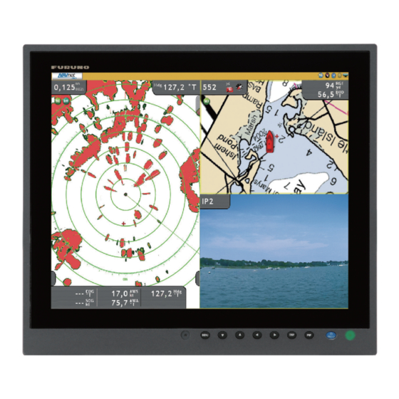
FOREWORD A Word to the Owner of the MU-190HD FURUNO Electric Company thanks you for purchasing the MU-190HD 19” Marine Display. We are confident you will discover why the FURUNO name has become synonymous with quality and re- liability. For over 60 years FURUNO Electric Company has enjoyed an enviable reputation for quality and reliability throughout the world. -
Page 7: System Configuration
FSV-30, FCV-30, FCV-1200L etc. MFD8/MFD12/MFDBB, 2 ports FAR-21X7 series etc. VIDEO (NTSC/PAL) CCD camera, DVD recorder, etc. 3 ports Environmental category MARINE DISPLAY MU-190HD: Protected from the weather MU-190HD 12-24 VDC Connectable equipment Equipment Resolution Signal FCV-1200L/M Analog RGB, via IF-8000 CH-250/S... -
Page 8: Equipment Lists
EQUIPMENT LISTS Standard supply Name Type Code No. Remarks Display Unit MU-190HD — w/ Hard cover Installation CP26-01400 000-016-269 1 set • CP26-01402* Materials • Flush Mounting Plate Assy. (CP26-01401, Code: 001-080-890) 2 pcs. • Cable Assembly (MJ-A3SPF0018-050ZC, Code: 000-154-025-10) 1 pc. -
Page 9: Mounting, Wiring
MOUNTING, WIRING Preparation Mounting type You can install the display unit as follows. See the outline drawing at the back of this manual for mounting dimensions. • Flush mounting, fix at rear (standard) • Flush mounting, fix at front (option) •... - Page 10 1. MOUNTING, WIRING The upper edge of the hard cover Pull forward the upper edge by pressing here with thumbs. How to remove the hard cover To attach the hard cover, follow the illustration in the figure below. Cutout Set the tabs on the top Push the tabs of the of the hard cover to the bottom of the hard cover...
-
Page 11: Flush Mounting (Fix At Rear)
1. MOUNTING, WIRING Flush Mounting (fix at rear) Flush mounting, fix at rear is the standard installation method. 1. Make a cutout in the mounting location with the “Flush mounting template” (included). 442±1 (17.40”) 4-ø18 (0.71”) 9 (0.35”) 2. Attach the flush mounting sponges H19 and V19 in the order shown in the figure below. Flush Mounting Sponge (H19) for top and bottom Flush Mounting Sponge (V19) - Page 12 1. MOUNTING, WIRING 4. Set the display unit to the cutout. Cutout 5. Screw the wing bolts and the wing nuts of the flush mount fixture so that the protector moves to the mounting plate. Wing Bolt Wing Nut Mounting Plate Protector Flush Mount Fixture 19 Set to the fixture.
- Page 13 1. MOUNTING, WIRING 6. Fasten the flush mount fixture 19 to the right and left sides of the rear of the display unit with the washer head screws (6 places). Flush Mount Fixture 19 Washer Head Screw 7. Fasten the wing bolts, in the order of the number shown in the figure below so that the protec- tors touch the mounting panel.
-
Page 14: Flush Mounting From The Front
1. MOUNTING, WIRING Flush Mounting from the Front If you do not have the enough space to fix the display unit from the rear, you can fix it from the front with the Flush mount kit OP26-7 (option). Flush Mount Kit OP26-7 (Code: 001-080-940) Name Type Code No. - Page 15 1. MOUNTING, WIRING 3. Attach the flush mounting panel to the display unit from the rear with the washer head screws (8 places). Flush Mounting Panel (19) Washer Head Screw 4. Connect all cables at the back of the display unit. See section 1.7. 5.
-
Page 16: Flush Mounting With Hood (Fix At Rear)
1. MOUNTING, WIRING Flush Mounting with hood (fix at rear) You can attach a hood when flush mounting the unit from the rear, using the hood assembly OP26-6 (option). Hood Assembly OP26-6 (Code: 001-080-930) Name Type Code No. Qty. Hood (19) Assembly OP26-6-1 001-080-970-00 Flush Mounting Sponge (V19) - Page 17 1. MOUNTING, WIRING 3. Attach the hood gaskets to the top and bottom brims. Then, attach the flush mounting sponge (V19) to the right and left brims, of the display unit from the rear side. F-mount Hood Gasket 19 Flush Mounting Sponge (V19) for top and bottom for left and right 4.
-
Page 18: Desktop Mounting
1. MOUNTING, WIRING 7. Press the top of the hood to fit the knobs in the cutouts. Press Press 8. Fix the hood assembly with the knobs tightly (4 places). Desktop Mounting You can fix the display unit to a desktop, using the bracket assembly OP26-5 (option). Bracket Assembly OP26-5 (Code: 000-016-270) Name Type... - Page 19 1. MOUNTING, WIRING 1. Loosen the knobs of the bracket support to separate the mounting bracket from the bracket support. Mounting Bracket (19) Bracket Support Knob 2. Set the mounting bracket to the mounting location with four self-tapping screws. Self-Tapping Screw 5x20 Mounting Bracket (19)
- Page 20 1. MOUNTING, WIRING 3. Attach the bracket support to the rear of the display unit with the binding head screws (9 plac- es). Binding Head Screw Screw (9 places) Bracket Support Rear of the display unit 4. Connect all cables at the back of the display unit. See section 1.7. 5.
-
Page 21: Flush Mounting A Series Side By Side
1. MOUNTING, WIRING Flush Mounting a Series Side by Side You can flush mount two display units side by side. 1. Make a cutout in the mounting location as shown below. 892±1 (35.12”) 4-ø18 (0.71”) 9 (0.35”) 2. Follow steps 2 to 5 in section 1.2 to set the two display units in the mounting location. 3. -
Page 22: Wiring
1. MOUNTING, WIRING Wiring Refer to figure below and the interconnection diagram at the back of this manual to connect ca- bles. Connector The bottom of the rear of the display unit Slide switch* Slide switch* Composite signal Composite signal cable cable RGB signal... - Page 23 1. MOUNTING, WIRING How to fix composite signal cable Fix the cables for the composite signal at the fixing terminal with the cable tie to prevent a loose connection. 1. Pass the cable tie (supplied) through the side of the fixing terminal. 2.
-
Page 24: Adjustments
ADJUSTMENTS Adjust the MU-190HD according to the equipment connected. RGB/DVI Setting You can adjust the screen from the [RGB], [DVI-D1] and [DVI-D2] ports separately. Turn on ex- ternal equipment and adjust the display unit as follows. 1. Select the signal to adjust at the DISP selection window. See section 3.4. - Page 25 2. ADJUSTMENTS 5. Press the key to adjust the setting. 6. Press the MENU key to close the menu. RGB/DVI menu descriptions Menu item Function Setting H_SIZE Adjusts the image size horizontally. Horizontal size: (narrow), (wide) Depending on input signal V_SIZE Adjusts the image size vertically.
-
Page 26: Video Composite Signal Setting
2. ADJUSTMENTS Video Composite Signal Setting You can adjust the VIDEO1, 2 or 3 signal from the VIDEO1, VIDEO2 and VIDEO3 ports separate- ly. The VIDEO1, 2 or 3 signal is displayed in the PIP window also. 1. Select the signal to adjust at the DISP selection window. 2. -
Page 27: The Menu Window Setting
2. ADJUSTMENTS The Menu Window Setting 2.3.1 How to adjust the menu window You can adjust the position and transparency of the menu window on the [OSD] (On Screen Dis- play) menu. 1. Press the MENU key to show the menu. 2. -
Page 28: How To Change The Signal Name
2. ADJUSTMENTS 2.3.2 How to change the signal name You can change the signal name (“RGB”, “DVI1” or “VIDEO1” etc.) to a name (ex. the equipment name) which is easy to understand. The changed name is shown in the DISP selection window, PIP selection window and the indication shown at the upper right of the screen. -
Page 29: Operation
OPERATION Controls MENU DISP *: It is available when the slide switch at the bottom of rear side is OFF. - Power On/Off.* - Display the brilliance Open/Close the menu. Select the signal to display. adjustment window. MENU DISP Light sensor - Select the menu and Display the PIP Lamp... -
Page 30: How To Turn The Power On/Off
Note 1: You can not turn on the power with the /BRILL key on MU-190HD. Note 2: When you connect the cables to both DVI-D1 and DVI-D2 ports, turn off the power of the both equipments to turn off the display unit. -
Page 31: How To Select The Source For Main Picture
3. OPERATION 2. Press the key to adjust the brilliance (available range: 1 to 50). You can also adjust the brilliance by pressing the /BRILL key repeatedly. 3. Press the key to close the window. Note 1: If you turn off the display unit with the minimum brilliance, you may become difficult to watch the screen because of the ambient light at the next start. -
Page 32: System Menu
3. OPERATION 1. When the RGB, DVI1 or DVI2 display appears, press the PIP key. The PIP selection window appears. The signal names are shown as you customize at paragraph 2.3.2 on the window. This window disappears if there is no operation for five sec- onds. -
Page 33: How To Adjust The Brilliance From The External Equipment
3. OPERATION 3. Press the key to select [AUTO DIMMER]. 4. Press the key to select the adjustment interval. [OFF]: Not adjusted automatically [3]: Every minute [1]: Every two seconds [4]: Every three minutes [2]: Every 30 seconds [5]: Every five minutes 5. -
Page 34: Maintenance, Troubleshooting
MAINTENANCE, TROUBLESHOOTING NOTICE Do not apply paint, anti-corrosive sealant or contact spray to coating or plastic parts of the equipment. Those items contain organic solvents that can damage coating and plastic parts, especially plastic connectors. Maintenance Routine maintenance Regular maintenance is important for good performance. Check the following on a regular basis to keep the equipment in good condition. -
Page 35: Troubleshooting
4. MAINTENANCE, TROUBLESHOOTING LCD replacement The life of the LCD is approximately 50,000 hours. The actual numbers of hours depends on am- bient temperature and humidity. When the brilliance cannot be raised sufficiently, replace the LCD. Fan replacement The life of the each fan is shown in the table below. Item Life FAN1, FAN3... -
Page 36: Specifications
FURUNO MU-190HD SPECIFICATIONS OF MARINE DISPLAY MU-190HD GENERAL Display 19-inch color LCD Effective area 376 x 301 mm approx. Resolution SXGA (1280 x 1024) Brightness 1,000 cd/m typical Contrast 900: 1 View angle 160° typical (left/right and up/down: 80° or more) - Page 37 重要なお知らせ 取扱説明書の一部または全部の転載、複写は著作権者である当社の許諾が必要です。無断転 載することを固くお断りします。 本書を紛失または汚損されたときは、次のアドレスにアクセスして、フルノライフベスト株 式会社からご購入ください。 http://www.furuno.co.jp/contact/cnt_manual.html 製品の仕様ならびに取扱説明書の内容は予告なく変更することがあります。 画面に表示される内容は、システムの設定や動作状態によって異なります。したがって、本 書内に掲載してあるイラストは画面の表示と異なる場合があります。 お客様が本書の内容に従わずに本機または本ソフトウェアを取り扱われたり、または当社お よび当社指定の者以外の第三者により改造・変更されることに起因して生じる障害等につい ては、当社は責任を負いかねますのでご了承ください。 お買い上げの機器を廃棄するときは、産業廃棄物として地方自治体の条例または規則に従っ て処理してください。詳しくは、各地方自治体に問い合わせてください。 本マニュアルに記載されている社名、製品名は、一般に各開発メーカーの登録商標または商 標です。...
- Page 38 安全にお使いいただくために [ 必ずお守りください ] お使いになる人や他の人への危害、財産への損害を未然に防止するため、以下のことを必ずお 守りください。表示内容を無視して誤った使い方をしたときに生じる危害や損害の程度を、本 書では次の表示で区分し、説明していますので十分に気をつけてください。...
- Page 39 安全にお使いいただくために...
- Page 40 目 次 はじめに ........................v システム構成 .........................vi 構成表...........................vii 1 章 取付けと結線...................... 1 準備............................1 標準構成での取付け(埋込み背面留め) .................. 3 埋込み前面留め(オプション) ....................6 フード付き埋込み背面留め (オプション) ................8 卓上取付け ( オプション )...................... 10 横並び連結取付け(埋込み背面留め) ................... 13 結線............................14 2 章 装備後の調整....................16 RGB、DVI1、DVI2 画面の設定 ..................... 16 VIDEO1、VIDEO2、VIDEO3 画面の設定...
-
Page 41: はじめに
はじめに このたびは、当社製品をお買い求めいただき、誠にありがとうございます。当社は 60 年以上に わたって数々の舶用電子機器を製造販売しており、性能、品質、信頼性については全世界の ユーザーの方々から高い評価を受けています。本機は、厳しい品質管理のもとで設計・製造さ れていますので、性能・耐久性ともに安心してご使用いただけます。この取扱説明書をよくお 読みいただき、本来の性能を十分発揮させていただきますようお願い申し上げます。 特徴 本機は、19 型の高輝度カラー LCD 表示器です。主な特徴は次のとおりです。 アナログ RGB 信号 1 系統、 デジタル信号 2 系統、 コンポジット信号 3 系統を接続し、 メニュー にて選択表示が可能 様々な機種との接続が可能(接続可能機種については「システム構成」参照) 高解像度表示[SXGA(1280x1024 ドット) ] 高輝度表示(最大輝度 1000cd/ ㎡、最小輝度 0.3cd/ ㎡以下) 光センサーによる自動調光機能付き ピクチャーインピクチャー機能付き DVI 信号による表示器の自動電源オン/オフ機能付き プログラム プログラム名... -
Page 42: システム構成
システム構成 接続可能機種 機種 解像度 信号形式 FCV-1200L/1200LM アナログ RGB、IF-8000 経由 CH-250/250S アナログ RGB、IF-8000 経由 CH-300 アナログ RGB、IF-8000 経由 CSH-5L/8L アナログ RGB FSV-24 SXGA アナログ RGB FSV-30 SXGA アナログ RGB FSV-84/84L SXGA アナログ RGB FCV-30 SXGA アナログ RGB CI-68/88 アナログ RGB FR-1510 MARK-3 アナログ... -
Page 43: 構成表
構成表 標準支給品 名称 型式 コード番号 数量 備考 MU-190HD – カラー LCD 表示器 ハードカバー付き CP26-01400 000-016-269 1 式 工事材料 • CP26-01402 • F マウント金具 19 組品 CP26-01401 (001-080-890)、2 個 • ケーブル組品 MJ-A3SPF0018-050ZC (000-154- 025-10)、1 本 FP26-00401 001-080-780 1 式 • フィルタークリーナー... -
Page 44: 章 取付けと結線
1 章 取付けと結線 準備 取付け方法 表示器は次のような方法で取り付けることができます。 • 標準構成での取付け(埋込み背面留め) • 埋込み前面留め(オプション) • フード付き埋込み背面留め(オプション) • 卓上取付け(オプション) • 横並び連結取付け(埋込み背面留め) 取付け寸法の詳細は、巻末の外寸図を参照してください。 注)LCD 管面は壊れやすいガラス素材でできているので、強い衝撃や圧力を加えないように注 意して取り付けてください。 取付け位置 次の点を考慮して取付け位置を決めてください。 • 取付け場所が表示器の重さに耐えられる場所 • 直射日光が LCD の表面に長時間当たらない場所 LCD に直射日光が長時間当たると、LCD がブラックアウト(黒くなる現象)する可能性が あります。 • 船の周囲の状況を観察しながら機器の操作ができる見通しの良い場所 • 巻末の外寸図に示す保守・点検用のスペースが確保できる場所 • 水しぶきのかからない場所 • コンパス安全距離(iii ページ参照)を確保できる場所 ハードカバーの取外し... - Page 45 1 章 取付けと結線 取外し 取付け 配線 表示器を取り付ける前に必要なケーブルを配線しておきます。配線は、巻末の相互結線図を参 照してください。...
-
Page 46: 標準構成での取付け(埋込み背面留め
1 章 取付けと結線 標準構成での取付け(埋込み背面留め) 標準構成では、表示器を背面から埋込み装備することができます。 1. 同梱の型紙を使って、装備場所に穴を開けます。 442±1 4-φ18 取付け穴寸法参考図 2. 表示器背面の上下つばに支給の F マウントスポンジ H19、および左右つばに F マウン トスポンジ V19 を貼り付けます。 スポンジは、下図の①~④の順に貼り付けてください。 3. 1.7 節の「結線」を参照して、必要なケーブルを表示器背面に接続します。... - Page 47 1 章 取付けと結線 4. 取付け穴に表示器をはめ込みます。 5. 支給の F マウント金具 19 組品(2 個)の蝶ナットと蝶ボルトを回して、ネジ足プロテ クタをマウント金具のほうに移動させます(下図参照) 。 Wing nut...
- Page 48 1 章 取付けと結線 6. 表示器背面から支給のナベセムス B ネジ(6 本)を使って、F マウント金具 19 組品を 表示器の左右に取り付けます。 蝶ボルトを下図の①~⑥の順に回して、ネジ足プロテクタが壁に当たるようにします。 8. もう一度、蝶ボルトを①~⑥の順に確実に締め付けて表示器を固定します。 9. 中間の蝶ナットを締め付けます。...
-
Page 49: 埋込み前面留め(オプション
1 章 取付けと結線 埋込み前面留め(オプション) 埋込み装備で背面留めするためのスペースがない場合には、オプションのフラッシュマウント キット OP26-7 を使用することで表示器前面から固定することができます。 フラッシュマウントキット OP26-7 (コード番号 : 001-080-940)内訳 名称 型式 コード番号 数量 OP26-7-1 001-080-980-00 F マウントパネル 19 組品 M4x10 000-163-836-10 ナベセムス B 000-162-609-10 トラスタッピンネジ 5x20 C42-00911 000-172-638-10 フラッシュマウント型紙 1. キットに同梱の型紙を使って、装備場所に穴を開けます。 4-φ18 460±0.5 取付け穴寸法参考図 2. 表示器背面の上下つばに支給の F マウントスポンジ H19、および左右つばに F マウン トスポンジ... - Page 50 1 章 取付けと結線 3. 表示器背面からナベセムス B ネジ(8 本)を使って、F マウントパネル 19 組品を取り 付けます。 4. 1.7 節の「結線」を参照して、必要なケーブルを表示器背面に接続します。 5. 手順 3 の組品を手順 1 の取付け穴にはめ込みます。 6. トラスタッピンネジ(4 本)を使って、表示器を固定します。...
-
Page 51: フード付き埋込み背面留め (オプション
1 章 取付けと結線 フード付き埋込み背面留め (オプション) 埋込み装備でフードを取り付けるには、オプションのフード 19 キット OP26-6 が必要です。 フード 19 キット OP26-6 (コード番号 : 001-080-930)内訳 名称 型式 コード番号 数量 OP26-6-1 001-080-970-00 フード 19 組品 26-005-3124 100-351-560-10 F マウントスポンジ V19 26-005-3302 100-351-611-10 フード固定金具 19 26-005-3305 100-351-620-10 フード F パッキン 19 03-163-2303 100-343-602-10 ローレットノブ... - Page 52 1 章 取付けと結線 3. 表示器背面の上下つばにキットのフード F パッキン 19 を貼り付け、その後、左右つば に F マウントスポンジ V19 を貼り付けます。 4. 1.2 節の「標準構成での取付け(埋込み背面留め) 」の手順 3 ~ 9 に従って、表示器を パネル(壁)に固定します。 5. フード固定金具 19 にローレットノブ(4 個)を緩く回してはめ込みます。 6. フード 19 組品の切り欠き部分をローレットノブとフード固定金具 19 の間に差し込み ます。...
-
Page 53: 卓上取付け ( オプション )
1 章 取付けと結線 7. 切り欠きとローレットノブが密着するように、フード 19 組品の上部を押さえます。 8. ローレットノブ(4 個)を締め付けて、フード 19 組品を固定します。 卓上取付け ( オプション ) 卓上に取り付けるには、オプションのハンガー 19 キット OP26-5 が必要です。 ハンガー 19 キット OP26-5(コード番号 : 000-016-270)内訳 名称 型式 コード番号 数量 OP26-5-1 001-080-910-00 ハンガー 19 組品 ハンガーブラケット 19 組品 OP26-5-2 001-080-920-00 5x20 000-162-608-10... - Page 54 1 章 取付けと結線 1. ハンガーブラケット 19 組品に付いているノブを緩めて、ハンガー 19 組品とハンガー ブラケット 19 組品を分離します。 2. 表示器取付け位置にハンガー 19 組品を置き、トラスタッピンネジ(4 本)で固定しま す。...
- Page 55 1 章 取付けと結線 3. バインド小ネジ(9 本)を使って、ハンガーブラケット 19 組品を表示器の背面に取り 付けます。 4. 1.7 節の「結線」を参照して、必要なケーブルを表示器背面に接続します。 5. ハンガーブラケット 19 組品に付いているノブを緩めて、ハンガー 19 組品の切り欠き に挿入します。 6. 表示器を希望する角度に調整して、ノブを締め付けます。...
-
Page 56: 横並び連結取付け(埋込み背面留め
1 章 取付けと結線 横並び連結取付け(埋込み背面留め) 表示器を 2 台横並びで取り付けることができます。 1. 取付け位置に下図のような取付け穴を開けます。 892±1 φ 取付け穴寸法参考図 2. 1.2 節の「標準構成での取付け(埋込み背面留め) 」の手順 2 ~ 5 に従って、表示器 2 台をパネル(壁)にはめ込みます。 3. 表示器背面から下図の位置に F マウント金具 19 組品をナベセムス B ネジで取り付け て、2 台の表示器を連結します。 4. 1.2 節の「標準構成での取付け(埋込み背面留め) 」の手順 7 ~ 9 を参照して、2 台の 表示器を固定します。... -
Page 57: 結線
1 章 取付けと結線 結線 下図および巻末の相互結線図を参照してケーブルを接続してください。 接続 * 1:スライドスイッチ • ON(上側): デジタル信号接続時、レーダーなどの 外部機器側で電源をオン/オフすると、表示器の電 源も連動します。 • OFF(下側): アナログ RGB 信号接続時は必ずオフに してください。 注)DVI ポートと RGB ポートの両方に外部機器を接続 している場合は、スライドスイッチの設定を 「OFF」にしてください。 * 2:BRILL CTRL ポート 現在使用できません。コネクタに貼ってあるシールをはがさないでください。... - Page 58 1 章 取付けと結線 ケーブル固定用端子 コンポジット信号ケーブルを接続した場合は、下図のようにケーブルを固定してください。振 動で抜けないようにするための処置です。 1. 支給のコンベックス(結束バンド)をケーブル固定用端子の穴に通します。 2. 結束バンド内にケーブルを通して結束バンドを締め付け、ケーブルをケーブル固定用 端子に固定します。 3. 不要な部分はニッパで切断します。...
-
Page 59: 章 装備後の調整
2 章 装備後の調整 本機に接続している機器に応じて、画面の各種設定を行います。 RGB、DVI1、DVI2 画面の設定 RGB、DVI-D1、DVI-D2 の各ポートに接続した機器の映像を個別に調整します。各機器の電源 を入れて映像を表示したあとに、次の調整を行います。 1. 入力信号ウィンドウで調整する画面を選びます(詳細は 3.4 節参照) 。 1) [DISP] キーを押します。 2) もう一度 [DISP] キーを押して、[RGB]、[DVI1]、[DVI2] のいずれかを選びます。 2. [MENU] キーを押して、メニューを表示します。 1 分間キー操作を行わなければ、自動的にメニューは消えます。 または キーを押して、[RGB]、[DVI1]、または [DVI2] を選びます。 カーソル(橙色)は、現在選んでいる項目を示します。選んだメニュー名に応じて、メ ニュー項目が変わります。[DVI1] と [DVI2] メニューの項目は、すべて同じです。 注)入力信号がない場合、メニュー名がグレー表示になり、設定を変更できません。 DVI1 DVI2 VIDEO1 VIDEO2 VIDEO3 OSD SYSTEM H_SIZE V_SIZE PHASE... - Page 60 2 章 装備後の調整 または キーを押して、変更するメニュー項目を選びます。 または キーを押して、設定内容を変更します。 6. [MENU] キーを押して、メニューを閉じます。 RGB、DVI メニューの説明 メニュー項目 説明 設定範囲 画面の横幅を調整する。 H_SIZE (狭まる) 、 (広がる) 入力信号による 画面の縦幅を調整する。 V_SIZE (狭まる) 、 (広がる) 入力信号をサンプリングするタイミングを調整する。 1 ~ 32 PHASE 数値を変更して文字等を見やすくする。 コントラストを調整する。 CONTRAST 1 ~ 64 (暗い) 、 (明るい) 1 ~...
-
Page 61: Video1、Video2、Video3 画面の設定
2 章 装備後の調整 VIDEO1、VIDEO2、VIDEO3 画面の設定 VIDEO1、VIDEO2、VIDEO3 の各ポートに接続した機器の映像を個別に調整します。VIDEO1 (または 2、3)の入力信号は、ピクチャーインピクチャー(PIP)ウィンドウにも表示されます (3.5 節参照) 。 1. 入力信号ウィンドウで調整する画面を選びます。 2. [MENU] キーを押して、メニューを表示します。 キーを押して、[VIDEO1]、[VIDEO2]、または [VIDEO3] を選びます。 または [VIDEO1]、[VIDEO2]、および [VIDEO3] メニューの項目は、すべて同じです。 RGB DVI1 DVI2 VIDEO1 VIDEO2 VIDEO3 OSD SYSTEM PIP_SIZE (1~10) CONTRAST (1~64) R_LEVEL (1~64) G_LEVEL (1~64) B_LEVEL (1~64) TEMPERATURE... -
Page 62: メニュー表示の設定
2 章 装備後の調整 メニュー表示の設定 2.3.1 メニューを調整する メニューの表示位置や表示方法を設定します。 1. [MENU] キーを押して、メニューを表示します。 または キーを押して、[OSD] を選びます。 RGB DVI1 DVI2 VIDEO1 VIDEO2 VIDEO3 SYSTEM H_POSITION (1~29) V_POSITION (1~37) TRANSLUCENT (OFF/ON) PIP SW TIME (OFF, 5~20) PIP SKIP (OFF, V1/V2/V3) CUSTOM NAME = RGB DVI1 = DVI1 DVI2 = DVI2... -
Page 63: 信号名を変更する
2 章 装備後の調整 メニュー項目 説明 設定範囲 上記の [PIP SW TIME] の設定を「5 ~ 20」にした場合は、映像を 表示する方法を選ぶ。 • OFF: VIDEO1→VIDEO2→VIDEO3→VIDEO1→…の順に映像が 切り替わる。 • V1: VIDEO2→VIDEO3→VIDEO2→…の順に映像が切り替わる OFF、V1、 PIP SKIP (VIDEO1 は表示されない) 。 V2、V3 • V2: VIDEO1→VIDEO3→VIDEO1→…の順に映像が切り替わる (VIDEO2 は表示されない) 。 • V3: VIDEO1→VIDEO2→VIDEO1→…の順に映像が切り替わる (VIDEO3 は表示されない) 。 CUSTOM NAME 2.3.2 項参照... -
Page 64: 章 操作
3 章 操作 操作パネルの説明 MENU DISP MENU DISP... -
Page 65: 電源のオン/オフ
3 章 操作 電源のオン/オフ ここでは、電源のオン/オフ、キーロック機能について説明します。 3.2.1 電源をオン/オフする 電源をオン/オフする方法は、表示器背面のスライドスイッチの設定によって異なります(装 備時に設定済み : 1.7 節参照) 。 スライドスイッチの設定が「ON」のとき DVI-D1 ポートまたは DVI-D2 ポートに接続している外部機器の電源スイッチに連動して、表示 器の電源がオン/オフされます(操作方法については、外部機器の取扱説明書を参照) 。 注 1)表示器の [ / BRILL] キーで電源を入れることはできません。 注 2)DVI-D1 ポートと DVI-D2 ポートの両方に外部機器を接続している場合、2 台の外部機器 の電源を切らないと表示器はオフになりません。 スライドスイッチの設定が「OFF」のとき 1. 表示器の [ / BRILL] キーを押して、電源を入れます。 2. -
Page 66: 輝度の調整
3 章 操作 輝度の調整 画面の輝度を調整します。 注)[SYSTEM] メニューの [AUTO DIMMER] を「OFF」に設定している場合のみ、この操作を 行えます(3.6.1 項参照) 。 1. [ / BRILL] キーを短く押して、輝度調整ウィンドウを BRILL 表示します。 5 秒間キー操作を行わなければ、自動的にウィンドウは 消えます。 キーを押して、輝度を調整します(設定範囲 : 1 ~ 50) 。 または / BRILL] キーを短く押すことで、調整することもできます。 または キーを押して、ウィンドウを閉じます。 注 1)輝度を最小に設定した状態で電源を切った場合、次回電源を入れたときに周囲の明るさ / BRILL] キーを何 によって、表示が見えづらいことがあります。このような場合は、[ 回か押してください。... -
Page 67: Pip ウィンドウ内の入力信号の選択
3 章 操作 PIP ウィンドウ内の入力信号の選択 PIP ウィンドウに表示させる入力信号を選びます。PIP ウィンドウは、RGB、DVI1、または DVI2 画面上に表示することができます。 1. RGB、DVI1、または DVI2 画面が表示されているときに、[PIP] キーを押します。 PIP 設定ウィンドウが表示されます。ウィンドウ内には、2.3.2 項で設定した信号名が表示 されます。5 秒間キー操作を行わなければ、自動的にウィンドウは消えます。 VIDEO1 VIDEO2 VIDEO3 PIP 設定ウィンドウ(工場出荷時の状態) または キーを押して、入力信号を選びます。 [PIP] キーを続けて押すことで、選ぶこともできます。[VIDEO1] ~ [VIDEO3] を選ぶと、 PIP ウィンドウが画面に現れます。PIP ウィンドウを表示させたくないときは、[OFF] を選 んでください。 または キーを押して、PIP 設定ウィンドウを閉じます。 4. -
Page 68: システムメニュー
3 章 操作 システムメニュー 輝度および初期化に関する設定は、[SYSTEM] メニューで行います。また、[SYSTEM] メ ニューで入力信号の情報やプログラムバージョン番号を確認できます。 3.6.1 自動調光機能をオン/オフする 自動調光機能をオンにすると、周囲の明るさに応じて、画面の輝度が自動的に調整されます。 また、輝度を調整する間隔を選ぶことができます。 注)表示器前面にある光センサーの前に物を置かないでください。明るさを感知できなくなり ます。 1. [MENU] キーを押して、メニューを表示します。 キーを押して、[SYSTEM] を選びます。 “Input Signal Searching. Please Wait.”というメッセージが出たあとに、[SYSTEM] メニュー が表示されます。 RGB DVI1 DVI2 VIDEO1 VIDEO2 VIDEO3 OSD SYSTEM AUTO DIMMER (OFF, 1~5) EXT BRILL CTRL (OFF DVI1 DVI2... -
Page 69: 設定を初期化する
3 章 操作 キーを押して、[SYSTEM] を選びます。 キーを押して、[EXT BRILL CTRL] を選びます。 または または キーを押して、次のいずれかを選びます。 • OFF: すべての画面の輝度を [ / BRILL] キーで調整する。 • DVI1: DVI1 画面を表示している場合、DVI-D1 ポートに接続している FAR-21X7 シリー ズから輝度を調整する(DVI1 以外の画面では [ / BRILL] キーが有効) 。 • DVI2: DVI2 画面を表示している場合、DVI-D2 ポートに接続している FAR-21X7 シリー ズから輝度を調整する(DVI2 以外の画面では... -
Page 70: 章 保守点検およびトラブルシューティング
4 章 保守点検およびトラブルシュー ティング 保守点検 ふだんの保守点検 機器の性能を十分に発揮させるには、定期的な点検が必要です。定期的に次の項目を点検して ください。 • 表示器背面のコネクタが確実に接続されているか確認します。 • アース端子に緩みや錆びがないか確認します。またアース線が確実に接地されているか確認 します。 • 表示器にほこりや汚れがついていないか確認します。ほこりや汚れは、柔らかい乾いた布で ふき取ってください。ひどい汚れは薄めた中性洗剤をしみ込ませた布でふいたあと、柔らか い布で空ぶきしてください。シンナーやアセトン、アルコール、ベンジンなどの有機溶剤を 使用しないでください。操作パネルの文字などが溶ける場合があります。 • LCD の表面にほこりや汚れがついていないか確認します。LCD の表面は傷が付きやすいの で、必ず支給のフィルタークリーナーでふいてください。 泥や塩などがこびり付いている場 合は、市販の OA ディスプレイクリーナーをティッシュに多めに染み込ませて、泥や塩を溶 かすようにゆっくりとふきます。泥や塩が付着したティッシュでふくと表面を傷付けますの で、こまめにティッシュを取り替えながらふいてください。シンナーやアセトン、アルコー ル、ベンジンなどの有機溶剤は使用しないでください。また、市販の油膜取り、曇り止めも 使用しないでください。画面(フィルター面)のコーティング剤が剥がれてしまいます。... -
Page 71: 故障かなと思ったら
4 章 保守点検およびトラブルシューティング ヒューズの交換 電源が入らない場合、ヒューズが切れている 可能性があります。ヒューズは電源ケーブル 内にあります。指定のヒューズと交換してく ださい。ヒューズを交換しても再び切れると きは、当社または当社代理店に連絡してくだ さい。 名称 型式 コード番号 備考 FGBO 125V 15A PBF 000-155-827-10 DC12V ヒューズ FGBO-A 125V 7A PBF 000-164-965-10 DV24V ヒューズ LCD 交換の目安 LCD の寿命時間は、約 50,000 時間です。実際の使用時間は、周囲の環境(温度、湿度)により 変動します。寿命がくると、輝度が低くなります。 ファン交換の目安 各ファンの寿命時間は、右表のとおりです。実際の使 用時間は、周囲の環境(温度)により変動します。寿 命がきたら、 “FAN1(または 2、3) ERROR”という メッセージが表示されます。電源を切り、当社または... - Page 72 FURUNO MU-190HD 19 型カラーLCD表示器 MU-190HD 仕 様 1.総合 (1) 表示器 19 型カラーLCD (2) 有効表示領域 約 376×301 mm (3) 解像度 SXGA(1280×1024 ドット) (4) 輝度 1,000 cd/m (5) コントラスト 900:1 (6) 視野角 160°(上下左右 80°以上) (7) 入力信号 アナログ RGB 1 ポート、ノンインタレース、RGB:0.7 Vp-p、同期:TTL DVI-D 2 ポート、DVI 規格準拠、VESA DDC2B...
-
Page 73: Installation Materials
001-080-900-00 26AE-X-9402 CODE NO. TYPE CP26-01402 工事材料表 INSTALLATION MATERIALS 数量 番 号 名 称 型名/規格 略 図 用途/備考 Q'TY OUTLINE NAME DESCRIPTIONS REMARKS ヒューズハリマーク 03-153-1312-0 ROHS FUSE LABEL CODE NO. 100-292-140-10 FマウントスポンジH19 26-005-3123-0 FLUSH MOUNTING SPONGE H 19 CODE NO. 100-351-550-10 FマウントスポンジV19 26-005-3124-0 FLUSH MOUNTING SPONGE V 19...
Need help?
Do you have a question about the Mu-190HD and is the answer not in the manual?
Questions and answers