SATO s84ex Operator's Manual
Hide thumbs
Also See for s84ex:
- Programming reference manual (452 pages) ,
- Operator's manual (404 pages) ,
- Configuration manual (2 pages)
Table of Contents
Advertisement
Quick Links
Advertisement
Table of Contents
Troubleshooting

Subscribe to Our Youtube Channel
Related Manuals for SATO s84ex


Summary of Contents for SATO s84ex
- Page 1 Operator Manual For printer model:...
- Page 2 Specifications and contents in this document are subject to change without notice. Trademarks SATO is a registered trademark of SATO Holdings Corporation and its subsidiaries in Japan, the U.S. and other countries. Secure Digital (SD) Card is a registered trademark of the SD Card Association.
-
Page 3: Table Of Contents
Table of Contents Table of Contents ................... 1 Before You Start ..................7 1 Parts Identification................15 1.1 Printer Orientation .................... 15 1.2 Parts Identification of the Printer ..............16 1.2.1 Front View ....................... 16 1.2.2 Rear View ........................ 17 1.2.3 Internal View ...................... - Page 4 Table of Contents 3 Loading the Ribbon and Media............37 3.1 Checking the Ink Side of the Ribbon............... 37 3.2 Loading the Ribbon ..................38 3.3 Removing the Ribbon ..................41 3.4 Usable Media ..................... 42 3.4.1 Adjusting the Position of the Media Sensor ............. 42 3.5 Loading Media ....................
- Page 5 Table of Contents 5 Cleaning and Performing Printer Adjustments ........ 193 5.1 Maintenance ....................193 5.2 Maintenance of the Print Head and Platen Roller ........194 5.2.1 Maintenance using the Cleaning Kit ..............194 5.2.2 Maintenance using the Cleaning Sheet ..............197 5.3 Adjusting the Base Reference Point .............
- Page 6 Table of Contents 6.5.5 IEEE1284 Interface ....................239 6.5.6 External Signal Interface (EXT) ................239 6.5.7 Wireless LAN Interface (Optional) ................. 240 7 Appendix ................... 241 7.1 List of Initial Values ..................241 7.1.1 Normal Mode ......................241 7.1.2 User Mode ......................241 7.1.3 Interface Mode.......................
- Page 7 Table of Contents 7.10.4 Ribbon Specification for the Ribbon Saver ............286 7.10.5 Label Specification for the Ribbon Saver ............286 7.11 Optional UHF RFID Configuration ............... 287 7.11.1 Printing RFID Tag Errors ..................289 7.11.2 RFID Error and Reset Timing ................292 7.11.3 External (EXT) Signal Interfaces when RFID Module is Enabled......
- Page 8 Table of Contents This page is intentionally left blank. S84-ex/S86-ex Operator Manual...
-
Page 9: Before You Start
• New designed sensor cover with nonstick surface that can be easily removed and cleaned without any tools. • Easily upload/download data to/from an SD card or USB memory, or by using the SATO All In One Tool application. • Supports remote printer setting through the SATO All In One Tool application or a web browser. -
Page 10: Safety Precautions
Then contact someone. your SATO reseller or technical support center. If you operate the printer in this Do not place containers filled with liquid on the condition, it could cause a fire or electric printer. - Page 11 • Do not disassemble or modify the printer. to a ground. Not grounding the ground Doing so could cause a fire or electric wire could cause an electric shock. shock. Contact your SATO reseller or technical support center to perform internal inspections, adjustments, and repairs.
- Page 12 Before You Start Caution Do not use in areas of high humidity. Top cover • Do not use the printer in areas of high • Be careful not to get your fingers pinched humidity or where condensation forms. If when opening or closing the top cover. condensation forms, immediately power Also be careful that the top cover does off the printer and do not use the printer...
-
Page 13: Power Supply
Before You Start Precautions for Installation and Handling Printer operation can be affected by the printer environment. Refer to the following instructions for installation and handling of the S84-ex/S86-ex printer. Select a Safe Location Do not place the printer in a location subject to water or oil. - Page 14 Before You Start Regulatory Approval FCC Warning This equipment has been tested and found to comply with the limits for a Class A digital device, pursuant to Part 15 of the FCC Rules. These limits are designed to provide reasonable protection against harmful interference when the equipment is operated in a commercial environment.
- Page 15 Before You Start Industry Canada (IC) Statement for Bluetooth This device complies with Industry Canada license-exempt RSS standard(s). Operation is subject to the following two conditions: • This device may not cause interference. • This device must accept any interference, including interference that may cause undesired operation of the device.
- Page 16 Before You Start (Pb) (Hg) (Cd) (Cr6+) (PBB) (PBDE) ABS PC SJ/T11363-2006 SJ/T11363- 2006 2006 2 28 SJ/T11364-2006 S84-ex/S86-ex Operator Manual...
-
Page 17: Parts Identification
Parts Identification 1.1 Printer Orientation This printer has two types of orientation as below. The media feed direction varies depending on the type of orientation. Media feed direction Media feed direction Americas: Standard/Right Hand Americas: Opposite/Left Hand Europe/Asia: Left Hand Europe/Asia: Right Hand Note The pictures in this manual show the S84-ex (Americas: Standard/Right Hand, Europe: Left Hand) printer,... -
Page 18: Parts Identification Of The Printer
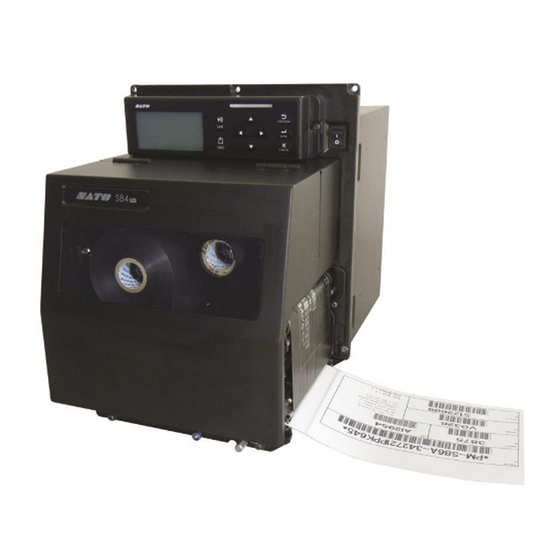
1 Parts Identification 1.2 Parts Identification of the Printer 1.2.1 Front View Operator panel Top cover Power (I/O) switch Press this switch to power on (I) or power off (O) the printer. Media discharge outlet S84-ex/S86-ex Operator Manual... -
Page 19: Rear View
1 Parts Identification 1.2.2 Rear View S84-ex/S86-ex S84-ex/S86-ex (Americas: Opposite/Left Hand, (Americas: Standard/Right Hand, Europe/Asia: Right Hand) printer Europe/Asia: Left Hand) printer Wireless LAN (optional) antenna LAN connector To install the optional wireless LAN antenna. To connect the printer to the host computer using the LAN interface. -
Page 20: Internal View
1 Parts Identification 1.2.3 Internal View USB connector (Type A) Ribbon rewind spindle For connecting to optional USB memory. Head lock lever Ribbon supply spindle Used to release the print head assembly. Media sensor adjustment knob Ribbon roller Used to adjust the position of the media ... -
Page 21: Parts On The Operator Panel
1 Parts Identification 1.3 Parts on the Operator Panel 1.3.1 Operator Panel Note: Remove the protective sheet from the operator panel before use. LINE button CANCEL button Toggle between online/offline mode. Go to the CANCEL PRINT JOB screen when the printer is in offline mode. -
Page 22: Led Indicator
1 Parts Identification 1.3.2 LED Indicator LED Indicator Color Description Blue Power on or online mode (Light off) Power off or offline mode Printer error (For example, when a machine error is detected) Printer error (For example, when the ribbon runs out) Flashes at intervals of two seconds. -
Page 23: Installing The Printer
Installing the Printer 2.1 Installation Precautions Install this printer in a location as follows: • A location that is horizontal and stable. When you install the printer onto a support structure/applicator, the complete assembly must be sturdy and stable. Attach the support structure firmly to the floor or on production machinery. •... -
Page 24: Installation Space
2 Installing the Printer 2.2 Installation Space For easy operation and correct airflow, make sure that there is sufficient space around the printer. The illustrations in this section show the printer from different angles, providing dimensions and spatial requirements. 2.2.1 Front View (S84-ex/S86-ex printer) 245 mm (9.6”) 117.5 mm... -
Page 25: Media Dispensed View (S84-Ex Printer)
2 Installing the Printer 2.2.3 Media Dispensed View (S84-ex printer) 43 mm (1.7”) Americas: Standard/Right Hand Europe/Asia: Left Hand 150 mm (5.9”) 131 mm (5.15”) 189 mm (7.4”) S84-ex/S86-ex Operator Manual... -
Page 26: Top View (S84-Ex Printer)
2 Installing the Printer 2.2.4 Top View (S84-ex printer) 150 mm (5.9”) 174 mm (6.85”) 223 mm (8.8”) 174 mm (6.85”) 150 mm (5.9”) 10 mm (0.4”) Americas: Standard/Right Hand 230 mm (9.1”) Europe/Asia: Left Hand S84-ex/S86-ex Operator Manual... -
Page 27: Media Dispensed View (S86-Ex Printer)
2 Installing the Printer 2.2.5 Media Dispensed View (S86-ex printer) 43 mm (1.7”) Americas: Standard/Right Hand Europe/Asia: Left Hand 150 mm (5.9”) 131 mm (5.15”) 243 mm (9.6”) S84-ex/S86-ex Operator Manual... -
Page 28: Top View (S86-Ex Printer)
2 Installing the Printer 2.2.6 Top View (S86-ex printer) 150 mm (5.9”) 174 mm (6.85”) 223 mm (8.8”) 174 mm (6.85”) 150 mm (5.9”) 10 mm (0.4”) Americas: Standard/Right Hand Europe/Asia: Left Hand 230 mm (9.1”) S84-ex/S86-ex Operator Manual... -
Page 29: Installing The Printer Onto A Support Structure/Applicator
2 Installing the Printer 2.3 Installing the Printer onto a Support Structure/Applicator This printer must be installed onto a support structure/applicator for correct operation. The printer has five bores on the center frame for installing to a support structure. Attach five bolts to the five bores on the center frame to install the printer onto the support structure. WARNING Make sure that you use the designated bolts that can accommodate the weight of the printer. -
Page 30: Checking The Bundled Accessories
2 Installing the Printer 2.4 Checking the Bundled Accessories After unpacking the printer, make sure that you have all the bundled accessories. If there are missing items, contact the SATO reseller where you purchased the printer. AC power cord* 14-pin conversion cable User documents (Quick guide, Warranty, etc.) -
Page 31: Connecting The Interface Cable
2 Installing the Printer 2.5 Connecting the Interface Cable The connection of the interface cable is explained as follows: 2.5.1 Available Interfaces This printer supports the following interfaces. Furthermore, a printer connected with multiple interface cables can continue to operate when receiving data. -
Page 32: Interface Settings
2 Installing the Printer Connect the applicator cable from the EXT connector of the printer to the applicator. Use a cable that is compatible with the standard of the interface board as stated in Section 7.13 Interface Specifications. Check the orientation of the connector before you make the connection. CAUTION Do not connect or disconnect the interface cables (or use a switch box) with power supplied to either the printer or computer. -
Page 33: Interface Combination
2 Installing the Printer 2.5.4 Interface Combination The interface combinations that can be used for the data port and sub port are as follows. Data Port RS-232C IEEE1284 Bluetooth WLAN RS-232C IEEE1284 Bluetooth WLAN NONE [o: configurable, x: not configurable] Note •... -
Page 34: Connecting The Power Cord
AC 100-240 V, 50-60 Hz. If your local voltage is not in the stated range, contact your SATO reseller or technical support center. *The shape of the power plug varies depending on the region in which it was purchased. -
Page 35: Power On/Off The Printer
2 Installing the Printer 2.7 Power On/Off the Printer WARNING Do not touch the power switch, connect or disconnect the power cord while your hands are wet. Doing so could cause an electric shock. 2.7.1 Power On the Printer Press the power switch on the operator panel to “I”... -
Page 36: Installing Optional Memory Storage
The optional SD card or USB memory can be used for uploading and downloading data (print format, graphics, extended characters) registered in the printer and printer firmware. Contact your SATO reseller or service center for the recommended SD card or USB memory. 2.8.1 Installing the Optional SD Card You can install an optional SD card into the SD card slot located on the rear of the printer. -
Page 37: Installing The Optional Usb Memory
Insert the optional USB memory into the USB connector (Series A plug, 2.0 High-speed) on the front of the printer. Contact your SATO reseller for the recommended USB memory. Close the top cover. To remove the USB memory from the printer Power off the printer before removing the USB memory. - Page 38 2 Installing the Printer This page is intentionally left blank. S84-ex/S86-ex Operator Manual...
-
Page 39: Loading The Ribbon And Media
Loading the Ribbon and Media This printer supports two types of print methods, namely thermal transfer and direct thermal. Thermal transfer is a print method that transfers the ink of the ribbon to the media using the heat of the print head. Direct thermal is a print method that creates the image on direct thermal media using the heat of the print head. -
Page 40: Loading The Ribbon
3 Loading the Ribbon and Media 3.2 Loading the Ribbon Use genuine media and ribbons for the printer, for optimum print quality. CAUTION • The print head and its surroundings are hot after printing. Be careful not to touch it, to avoid being burned. •... - Page 41 3 Loading the Ribbon and Media Turn the head lock lever clockwise to unlock the print head. Load the ribbon onto the ribbon supply spindle . While taking note of the wind direction, insert the ribbon all the way in. Make sure that the ink side of the ribbon is facing down when passing it below the print head.
- Page 42 3 Loading the Ribbon and Media From the ribbon supply spindle , pass the ribbon below the print head and to the ribbon rewind spindle . Wind the ribbon clockwise around the empty ribbon core on the ribbon rewind spindle .
-
Page 43: Removing The Ribbon
3 Loading the Ribbon and Media 3.3 Removing the Ribbon Open the top cover. Turn the head lock lever clockwise to unlock the print head. Pull to remove the used ribbon from the ribbon rewind spindle . Pull to remove the empty core from the ribbon supply spindle . -
Page 44: Usable Media
3 Loading the Ribbon and Media 3.4 Usable Media This printer can print on two types of media; media roll and fan-fold media. The printer uses sensors to detect I-marks or Gaps on the media in order to precisely print the content. 1.5 mm (0.06”) 1.5 mm (0.06”) 3 mm (0.12”) -
Page 45: Loading Media
3 Loading the Ribbon and Media 3.5 Loading Media Use genuine media and ribbons for the printer, for optimum print quality. CAUTION • The print head and its surroundings are hot after printing. Be careful not to touch it, to avoid being burned. •... - Page 46 3 Loading the Ribbon and Media Turn the head lock lever clockwise to unlock the print head. Pull the feed lock latch to unlock the feed roller and media sensor assembly . The feed roller and media sensor assembly will flip open.
- Page 47 3 Loading the Ribbon and Media Push the pressure roller release tab up to release the pressure roller plate . Pass the liner through the gap of the pressure roller plate . Push the center of the pressure roller plate ...
-
Page 48: Loading Media Without Using Dispenser
3 Loading the Ribbon and Media 3.5.2 Loading Media without Using Dispenser This section describes the procedure to just load the media without using the dispenser. The routing path of the media is shown in the right picture. When loading the media, make sure that the print side is facing up. -
Page 49: Operation And Configuration
Operation and Configuration 4.1 Display and Operation The display of the printer varies depending on the following modes: • Normal mode: refer to Section 4.1.1 Normal Mode Display and Icons. • Setting mode menu: refer to Section 4.1.2 Setting Mode Menu and Icons. - Page 50 4 Operation and Configuration • Trace mode status Icon Description Shows after receiving any data while trace mode is ENABLE. Shows after receiving ESC (1BH) A while trace mode is ENABLE. Shows after print operation while trace mode is ENABLE. •...
- Page 51 4 Operation and Configuration • Buzzer volume Icon Description Shows when the volume is level 3 (Loud). Shows when the volume is level 2 (Medium). Shows when the volume is level 1 (Low). Shows when the volume is level 0 (Mute). •...
-
Page 52: Setting Mode Menu And Icons
4 Operation and Configuration 4.1.2 Setting Mode Menu and Icons In the setting mode menu, the screen is shown as follows. Selected setting mode Setting mode icons When an icon is Valid arrow buttons selected, its color is for selection. inverted. -
Page 53: Error Display And Icons
4 Operation and Configuration 4.1.3 Error Display and Icons When a printer error occurs, the screen shows the following error messages and icons. Error number icon Error icon Error message Shows the valid arrow button to switch the screen. Alternates every three seconds. Countermeasure message •... -
Page 54: Setting Display
4 Operation and Configuration Icon Description Calendar error is detected. Writing information to the RFID tag failed. Wireless LAN setting error is detected. Any printer error other than above is detected. Error number according to the errors. 4.1.4 Setting Display In various setting mode, the setting display is shown as follows. - Page 55 4 Operation and Configuration • Setting values Goes to the setting mode menu without saving the setting. Save the value and go to the next screen. Returns to the previous screen without saving Setting item Setting contents Valid arrow Move the cursor Change the value of the setting.
-
Page 56: Operating Modes
4 Operation and Configuration 4.2 Operating Modes The printer contains a variety of the following operating modes: Click on the blue links below to go directly to the details of the selected operating mode. • Online Mode/Pause Mode/Offline Mode • Adjusting the Display Brightness •... - Page 57 4 Operation and Configuration The flow chart provides a clear summary of all the modes and their access methods. buttons Power off (Press for 5 seconds) Work Shift Work shift Setting Mode setting mode Print pause request/ Online state button Power on button Sound...
- Page 58 4 Operation and Configuration Power off Test Print Power on Test print mode Mode Default Power on Default setting Setting Mode mode Download Power on Download Mode mode Upload Power on Upload Mode mode Power on Hidden Hidden setting Setting Mode mode Wireless LAN Power on...
-
Page 59: Online Mode/Pause Mode/Offline Mode
4 Operation and Configuration 4.2.1 Online Mode/Pause Mode/Offline Mode In online mode, the printer is ready to receive print data from the host computer or other connected devices and start the print job. Adjust the buzzer volume. Changes to settings mode. Press simultaneously for Shows the remaining Enters offline mode... -
Page 60: Adjusting The Display Brightness
4 Operation and Configuration 4.2.2 Adjusting the Display Brightness In normal mode (online or offline), press the buttons repeatedly to adjust the display brightness. You can adjust the brightness in thirty-two steps (sixteen left and sixteen right). The brightness changes one step for every press of the button or button. -
Page 61: Canceling The Print Job
4 Operation and Configuration 4.2.4 Canceling the Print Job Cancel the print job according to the following procedure: Press the LINE button to change the printer to offline mode. Press the CANCEL button. CANCEL PRINT JOB shows to confirm the cancelation of the print job. -
Page 62: Adjustment Mode
4 Operation and Configuration 4.2.5 Adjustment Mode The printer has a quick access to the adjustment mode for setting the print position, stop position and print darkness. These adjustments are in conjunction with the configuration adjustments performed in the user mode menu. * Press the button to set the value. - Page 63 4 Operation and Configuration DARKNESS Fine tune the print darkness. The setting range is from 00 to 99. 00 is the lightest and 99 is the darkest. After adjustment, press the FUNCTION button or CANCEL button to exit the adjustment mode. The printer enters offline mode. Note Pressing the FUNCTION button or...
-
Page 64: Work Shift Setting Mode
4 Operation and Configuration 4.2.6 Work Shift Setting Mode This mode allows for specific production shift information to be printed on a label when used with the printer SBPL command. The flowchart shows the sequence of the setting screens for the work shift mode. The table describes each setting screen in detail. - Page 65 4 Operation and Configuration ENTER SHIFT TIME Set the printer start time in 24-hour format. Press the buttons to shift the cursor and press the buttons to change the value. Press the ENTER button to save the value and proceed to the next setting screen.
-
Page 66: Simple Standalone Mode
4 Operation and Configuration 4.2.7 Simple Standalone Mode This mode allows the printer to function independently from a host computer once a fixed format has been sent and saved to the SD card or USB memory. The data may be saved to the SD card or USB memory while in the print buffer, then recalled later with a new print quantity specified. - Page 67 4 Operation and Configuration STANDALONE MODE Select the following options using the buttons and then press the ENTER button. • LOAD: Read and print the file. • SAVE: Save the received print data to a file. Note Three beeps will sound if you select SAVE and press the ENTER button when there is no received data.
- Page 68 4 Operation and Configuration RECEIVE DATA COPYING. . . This screen shows that the received data is being copied. SAVE COMPLETED shows when the received data is fully copied. Note Three beeps will sound if the printer fails to copy the received data. The printer returns to the STANDALONE MODE screen.
-
Page 69: Setting Mode Menu
4 Operation and Configuration 4.2.8 Setting Mode Menu In the settings mode menu, the setting modes are shown as follows: Menu Description Returns to online mode. Online mode Access the settings related to the basic user configurations. User mode Access the settings related to the interfaces. Interface mode Access the settings related to the memory. - Page 70 4 Operation and Configuration The functions of the buttons in the setting mode menu are shown as below. Enters offline mode. Enters the selected setting mode. Enters offline mode. Selected Selected icon Navigate to Valid arrow buttons setting highlighted select the for selection.
-
Page 71: User Mode
4 Operation and Configuration 4.2.9 User Mode The flowchart shows the sequence of the setting screens for the user mode. The table describes each setting screen in detail. * Press the button to select an item or set the value button accordingly. - Page 72 4 Operation and Configuration * Press the button to select an item or set the value accordingly. The active arrow icons button button are shown on the screen. Select YES + button button button Select NO + button button button button Select DISABLE button...
-
Page 73: Print Speed
4 Operation and Configuration PRINT SPEED The setting range varies depending on the model. • S84-ex (203 dpi): 4 to 16 ips (inches/sec) • S86-ex (203 dpi): 4 to 14 ips (inches/sec) • S84-ex (305 dpi): 4 to 14 ips (inches/sec) •... - Page 74 4 Operation and Configuration 2 BYTE FONTS Set the kanji code to be used. • GB18030: Set for use with simplified Chinese. • BIG5: Set for use with traditional Chinese. • KSX1001: Set for use with Korean. The following kanji codes are available if GB18030 is selected: •...
- Page 75 4 Operation and Configuration CLEAN PRINTER Set the notification distance for cleaning the printer. The setting range is from 000 to 999 m. Note The notification function will be disabled if the distance is set to 0. CHANGE ROLLER Set the notification distance for changing the platen roller. The setting range is from 000 to 150 km.
-
Page 76: Interface Mode
4 Operation and Configuration 4.2.10 Interface Mode The flowchart shows the sequence of the setting screens for the interface mode. The table describes each setting screen in detail. * Press the button to select an item or set the value accordingly. - Page 77 4 Operation and Configuration * Press the button to select an item or set the value accordingly. The active arrow icons are shown on the screen. * Pressing the button on each screen will revert to the INTERFACE MODE menu. button button Shows only when...
- Page 78 4 Operation and Configuration * Press the button to select an item or set the value accordingly. The active arrow icons are shown on the screen. * Pressing the button on each screen will revert to the button button INTERFACE MODE menu. ENABLE+ button button...
- Page 79 4 Operation and Configuration * Press the button to select an item or set the value accordingly. The active arrow icons are shown on the screen. button * Pressing the button on each screen will revert to the button INTERFACE MODE menu. button button button...
- Page 80 4 Operation and Configuration * Press the button to select an item or set the value accordingly. The active arrow icons are shown on the screen. * Pressing the button on each screen will revert to the button button INTERFACE MODE menu. button SNMPv3+ button...
- Page 81 4 Operation and Configuration PRESS ENTER KEY This screen reminds the user to press the ENTER button to change or power off the printer to save the setting. INTERFACE AUTO SELECT Enable or disable the interface auto detection. • ENABLE: Automatically select the connected interface. •...
- Page 82 4 Operation and Configuration DATA PORT Select the connected interface for use with the data port. The options are as follows: • USB • LAN • RS-232C • IEEE1284 • Bluetooth • WLAN Note • Bluetooth shows even if a Bluetooth adapter is not connected. •...
- Page 83 4 Operation and Configuration IGNORE CAN/DLE Ignore or acknowledge the CAN/DLE code of the received data. • YES: Ignore the CAN/DLE code. • NO: Do not ignore the CAN/DLE code. Note Shows only if PROTOCOL is set to STATUS4. SNTP FUNCTION Enable or disable the SNTP function.
- Page 84 4 Operation and Configuration NTP IPv6 ADDRESS Set the IPv6 address for NTP server. Select the number of characters using the buttons and then press ENTER button. The setting range is from 0000:0000:0000:0000:0000:0000:0000:0000 to FFFF:FFFF:FFFF:FFFF:FFFF:FFFF:FFFF:FFFF. Note Shows only if the SNTP function is enabled. TIME ZONE Set the time zone.
- Page 85 4 Operation and Configuration SNMP SET SELECT Select SNMP settings. • SNMP SETTING: Sets the SNMP settings. When select it, goes to “SNMP setting” screen. • SNMP TRAP SET: Selects the trap number of SNMP. When select it, goes to “SNMP trap setting” screen. SNMP SETTING Select community and authentication of SNMP.
- Page 86 4 Operation and Configuration COMMUNITY NAME Input SNMP community name. • When SNMPv1/v2c[1] is selected the default is “public”. • When SNMPv1/v2c[2] is selected the default is “ ” (none). Note • Up to 32 alphanumeric characters and symbols (from 20H to 7EH) can be set.
- Page 87 4 Operation and Configuration AUTH PROTOCOL Select SNMP authentication protocol. The options are as follows: • NONE • MD5 • SHA-1 Note The setting will be effective only if you power on the printer again. AUTH KEY Input SNMP authentication key. Input more than 8 characters for the authentication name.
- Page 88 4 Operation and Configuration PRIVACY KEY Input SNMP privacy key. Input more than 8 characters for the authentication name. Press the buttons to shift the cursor and press the buttons to change the value. Press the ENTER button to save the value and proceed to the next setting screen.
- Page 89 4 Operation and Configuration COMMUNITY NAME Input SNMP trap community name. Input more than 8 characters for the authentication name. Press the buttons to shift the cursor and press the buttons to change the value. Press the ENTER button to save the value and proceed to the next setting screen.
- Page 90 4 Operation and Configuration AUTH KEY Input SNMP trap authentication key. Input more than 8 characters for the authentication name. Press the buttons to shift the cursor and press the buttons to change the value. Press the ENTER button to save the value and proceed to the next setting screen.
- Page 91 4 Operation and Configuration FINISH SETTING? Confirm to complete the setting. • YES: Returns the user mode screen. • NO: Returns to the NOTICE FUNCTION screen to select an item. S84-ex/S86-ex Operator Manual...
- Page 92 4 Operation and Configuration USB Setting * Press the button to select an item or set the value accordingly. The active arrow icons are shown on the screen. button * Pressing the button on each screen will revert to the INTERFACE MODE menu.
- Page 93 4 Operation and Configuration BCC CHECK Set the BCC check function. • ENABLE: Enable the BCC check function. • DISABLE: Disable the BCC check function. Note Shows only if PROTOCOL is set to STATUS5. S84-ex/S86-ex Operator Manual...
- Page 94 4 Operation and Configuration LAN/Wireless LAN Setting * Press the button to select an item or set the value accordingly. The active arrow icons are shown on the screen. * Pressing the button on each screen will revert to the INTERFACE MODE menu.
- Page 95 4 Operation and Configuration * Press the button to select an item or set the value accordingly. The active arrow icons are shown on the screen. * Pressing the button on each screen will revert to the INTERFACE MODE menu. button Shows only when the...
- Page 96 4 Operation and Configuration DHCP SETTING Enable or disable DHCP. • ENABLE: Enable DHCP. • DISABLE: Disable DHCP. Note • Shows only if the LAN or WLAN interface is selected. • The setting for the WLAN interface will be effective only if you power on the printer again.
- Page 97 4 Operation and Configuration IPv6 RESOLUTION Select IPv6 address setting method. The options are as follows: • AUTO • MANUAL • DHCP Note Shows only if the LAN interface is selected. IPv6 ADDRESS Set the IPv6 address. Note Shows only if the LAN interface is selected and “MANUAL” is selected at “IPv6 RESOLUTION”...
- Page 98 4 Operation and Configuration PORT NUMBER Set the LAN port numbers, 1 to 3. The setting range is from 00001 to 65535. Note • Shows only if the LAN interface is selected. • Each port (1, 2 and 3) must be set to different values. •...
- Page 99 4 Operation and Configuration PROTOCOL Set the communication protocol. • STATUS3: When selected, the printer will proceed to the IGNORE CR/ LF screen. • STATUS4: When selected, the printer will proceed to the STATUS REPLY TIMING screen. • STATUS5: When selected, the printer will proceed to the ITEM NO. CHECK screen.
- Page 100 4 Operation and Configuration RS-232C Setting * Press the button to select an item or set the value accordingly. The active arrow icons are shown on the screen. button * Pressing the button on each screen will revert to the INTERFACE MODE menu.
- Page 101 4 Operation and Configuration BAUDRATE Set the RS-232C baud rate. The following baud rates are available: • 2400 (bps) • 4800 (bps) • 9600 (bps) • 19200 (bps) • 38400 (bps) • 57600 (bps) • 115200 (bps) Note • Shows only if the RS-232C interface is selected. •...
- Page 102 4 Operation and Configuration CHARACTER BIT Set the RS-232C data length. The following options are available: • 7BIT • 8BIT Note • Shows only if the RS-232C interface is selected. • The setting will be effective only if you power on the printer again. PROTOCOL Set the communication protocol.
- Page 103 4 Operation and Configuration BCC CHECK Set the BCC check function. • ENABLE: Enable the BCC check function. • DISABLE: Disable the BCC check function. Note Shows only if PROTOCOL is set to STATUS5. RECEIVE BUFFER Set the receive buffer type. •...
- Page 104 4 Operation and Configuration IEEE1284 Setting * Press the button to select an item or set the value accordingly. The active arrow icons are shown on the screen. * Pressing the button on each button screen will revert to the INTERFACE MODE menu.
-
Page 105: Receive Buffer
4 Operation and Configuration PROTOCOL Set the communication protocol. • STATUS4: When selected, the printer will proceed to the RECEIVE BUFFER screen. • STATUS5: When selected, the printer will proceed to the ITEM NO. CHECK screen. ITEM NO. CHECK Set the item number check function. •... - Page 106 4 Operation and Configuration IEEE1284 ACK SIGNAL Set the width of the IEEE1284 ACK signal. The setting range is from 00.5 µs to 12.0 µs, and is adjustable in 0.1 µs steps. Note Shows only if the IEEE1284 interface is selected and RECEIVE BUFFER is set to 1ITEM.
- Page 107 4 Operation and Configuration Bluetooth Setting * Press the button to select an item or set the value accordingly. The active arrow icons are shown on the screen. button * Pressing the button on each screen will revert to the INTERFACE MODE menu.
- Page 108 4 Operation and Configuration AUTHENTICATION LEVEL Set the Bluetooth authentication level. The following options are available: • NONE: No authentication • Level 2-1: PIN code authentication, service level • Level 2-2: PIN code authentication, service level • Level 3: PIN code authentication, link level Note •...
- Page 109 4 Operation and Configuration PARAMETER SETTING(ISI) Set the Bluetooth communication parameter (ISI). The setting range is from 0012 to 1000. Note • Shows only if the Bluetooth interface is selected and DETECTING SETTING is enabled. • You cannot set the ISI value if it is smaller than the ISW value. •...
- Page 110 4 Operation and Configuration PROTOCOL Set the communication protocol. The following options are available: • STATUS3 • STATUS4 CRC CHECK Set the CRC check function. • ENABLE: Enable the CRC check function. • DISABLE: Disable the CRC check function. Note Shows only if the Bluetooth interface is selected.
-
Page 111: Memory Mode
4 Operation and Configuration 4.2.11 Memory Mode The flowchart shows the sequence of the setting screens for the memory mode. The table describes each setting screen in detail. * Press the button to select an item or set the value accordingly. - Page 112 4 Operation and Configuration Select “STORED Select “FORMAT” CONTENT” + button button Select “MEMORY SIZE” button button button button button button button button button button Select “NO” button Select “YES” button or button button Select “NO” + Select “YES” button button button button...
- Page 113 4 Operation and Configuration Select “SETTING UPLOAD” + button Select “SETTING SAVE” + button button button button button Saving Update completed? completed? Reading the data Reading the data Finished receiving the uploaded data Finished receiving the uploaded data Writing the data Writing the data Finished writing the uploaded data Finished writing the uploaded data...
- Page 114 4 Operation and Configuration CARD SLOT SELECT Set the memory storage allocation for each card slot for use with the Memory card command <CC>. A total of three slots can be set (Slot 0-2). Each card slot can be allocated to the following options: •...
- Page 115 4 Operation and Configuration MEMORY SIZE Check the free size of the selected memory. The memory unit (BYTE, KB, MB, GB) changes automatically according to the free space of the memory. Note After you press the ENTER button, the screen returns to MEMORY CARD MODE.
- Page 116 4 Operation and Configuration MEMORY FORMAT Select whether or not to format the memory. • YES: Format the memory. • NO: Do not format the memory. Note If you select NO, the screen returns to MEMORY CARD MODE. FORMAT START Confirm to start formatting the memory.
- Page 117 4 Operation and Configuration SELECT MEMORY DESTINATION Select the memory to save the printer setting information. The following options are available: • SD CARD • USB MEMORY Note • Shows only if MEMORY MODE is set to SETTING SAVE. • The setting information of the wireless LAN is saved only if the wireless LAN is connected.
- Page 118 4 Operation and Configuration SELECT MEMORY ORIGIN Select the memory to copy the printer setting information. The following options are available: • SD CARD • USB MEMORY Note Shows only if MEMORY MODE is set to SETTING UPLOAD. READING (SETTING UPLOAD) Shows while the printer is reading the setting information data.
-
Page 119: Service Mode
4 Operation and Configuration 4.2.12 Service Mode In the SERVICE MODE menu, you can perform sensor level adjustments and various function settings of the printer. * Press button to select item accordingly. The active arrow icons are shown on the screen. button button Shows only when the... - Page 120 4 Operation and Configuration Sensor Level Adjustments The flowchart shows the sequence of the setting screens for the sensor level adjustments. The table describes each setting screen in detail. * Press the button to select an item or set the value accordingly.
- Page 121 4 Operation and Configuration SENSOR LEVEL Set the sensor adjustment method. • AUTO: Automatically adjust the sensor level. • MANUAL: Manually adjust the sensor level. SENSOR SELECT Select the media sensor type for the sensor adjustment. • I-MARK: Adjust the I-mark sensor. •...
- Page 122 4 Operation and Configuration CALIBRATION COMPLETE/FAILED This screen shows the result of the automatic sensor adjustment. • COMPLETE: The automatic adjustment has succeeded. • FAILED: The automatic adjustment has failed. Press the ENTER button to proceed to the next screen. CALIBRATION Select to exit the automatic sensor adjustment or retry the automatic sensor adjustment.
- Page 123 4 Operation and Configuration SENSOR LEVEL I-MARK SLICE Shows the current level (Reception) of the I-mark sensor on the upper part of the screen. The slice level is calculated automatically and shown on the bottom line. The slice level can be set to 0.0 V, or from 0.3 V to 2.9 V. (adjustable in increments of 0.1 V) Note •...
- Page 124 4 Operation and Configuration Function Settings The flowchart shows the sequence of the setting screens for the function settings. The table describes each setting screen in detail. * Press the button to select an item or set the value accordingly. The active arrow icons are shown on the screen. * Pressing the button on each screen will revert to the SERVICE MODE setting screen.
- Page 125 4 Operation and Configuration * Press the button to select an item or set the value accordingly. The active arrow icons are shown on the screen. * Pressing the button on each screen will revert to the SERVICE button MODE setting screen. button button button...
- Page 126 4 Operation and Configuration * Press the button to select an item or set the value accordingly. The active arrow icons are shown on the screen. * Pressing the button on each screen will revert to the SERVICE MODE setting screen. button button button...
- Page 127 4 Operation and Configuration * Press the button to select an item or set the value accordingly. The active arrow icons are shown on the screen. * Pressing the button on each screen will revert to the SERVICE MODE setting screen. button button button...
- Page 128 4 Operation and Configuration AUTO ONLINE FEED Set the auto online feed function. This function enables the printer to automatically feed media in online mode after power on. • YES: Feed the media in online mode at power on. • NO: Do not feed the media in online mode at power on. FEED ON ERROR Set the online feed function.
- Page 129 4 Operation and Configuration CALENDAR REPRINT Perform the calendar reprint setting. • YES: The updated calendar data (date and time) according to the RTC (Real Time Clock) is included in the reprint data. • NO: Print exactly the same data as before. Note Shows only if EXTERNAL REPRINT is set to ENABLE, REPRINT W/ FEED is set to YES, FUNCTION KEY is set to REPRINT, or...
-
Page 130: Backfeed Speed
4 Operation and Configuration PREND TYPE 3/4 Select whether to reflect the label feed/stop timing on PREND output signal in External signal MODE3, 4. • NORMAL: Do not reflect the label feed/stop timing on PREND output. Print Print End (PREND) Mode 1 Mode 2 Mode 3... -
Page 131: Select Language
4 Operation and Configuration SELECT LANGUAGE Set the LCD language. The following languages are available: • ENGLISH • FRENCH • GERMAN • SPANISH • ITALIAN • PORTUGUESE • CHINESE (Simplified Chinese) PRIORITY SETTING Set the priority for the system commands. •... - Page 132 4 Operation and Configuration SET PASSWORD Enable or disable password input to various modes. • ON: Password input is required to enter various modes. • OFF: Password input is not required to enter various modes. You can enable password input for the following modes: USER MODE, INTERFACE MODE, MEMORY MODE, ADVANCED MODE, HEX DUMP MODE and SERVICE MODE PASSWORD NO.
- Page 133 4 Operation and Configuration COMPATIBLE MODE HEAD SIZE Set the head width for S86-ex series models. The options vary depending on the head density. Corresponding head width are as follows: Model Name Option Head Width (mm) S86-ex (203 dpi) NORMAL 167.5 M8460Se 152.0...
- Page 134 4 Operation and Configuration PRINTER MODEL Select the printer model based on print darkness in compatible mode. • M8485/90/60/65Se: Triple the value for Print Darkness <#E> and set it as the print darkness. Print Darkness value <#E> The value converted as Print Darkness value <#F>...
-
Page 135: Media Length
4 Operation and Configuration MEDIA LENGTH Set the maximum length of the media to be used. This function affects the printable area (lengthwise) and the media size checking function. It is necessary to set this value based on the actual media length to be used. - Page 136 4 Operation and Configuration MEMORY SELECT Select the storage memory for saving the printer operation log. SD CARD or USB MEMORY can be selected. Note Shows only if SAVE PRINT LOG is set to ENABLE. CLEAR PRINT LOG Select whether or not to clear the history data in the memory card. •...
- Page 137 4 Operation and Configuration RIBBON TENSION ADJUSTMENT Adjust the ribbon tension for the backfeed if scuffing (horizontal black line) occurs. The ribbon is tensed when using a smaller value, and is loosened when using a larger value. The setting range varies depending on the head density as follows: Head Density Setting Range Default...
- Page 138 4 Operation and Configuration BACKFEED OFFSET Set the backfeed distance in LINERLESS mode. The setting range is from 000 to 250 mm. Note Shows only if PRINTER TYPE in ADVANCED MODE is set to LINERLESS. TOTAL QTY DISPLAY Set whether or not to show the total print quantity. •...
- Page 139 4 Operation and Configuration REGION CODE Set the region code of the wireless LAN. The channel range varies depending on the region code as follows: Region Region Code Channel Range 1 - 11ch CANADA CANADA 1 - 11ch Europe EUROPE 1 - 13ch Malaysia MALAYSIA...
- Page 140 4 Operation and Configuration FONT SELECT Select a font from the stored fonts. • GB18030: Simplified Chinese • BIG 5: Traditional Chinese • KSX1001: Korean • YES: Printable • NO: Non-printable Move the cursor using the buttons, change the value using the buttons and then press the ENTER button to set the value.
- Page 141 4 Operation and Configuration DEFAULT SETTING COMPLETED Shows when the printer settings have been saved completely. Note The setting will be effective only if you power on the printer again. S84-ex/S86-ex Operator Manual...
-
Page 142: Advanced Mode
4 Operation and Configuration 4.2.13 Advanced Mode The advanced mode lets you configure the more advanced features of the printer hardware. The flowchart shows the sequence of the setting screens for the advanced mode. The table describes each setting screen in detail. * Press the button to select an item or set the value accordingly. - Page 143 4 Operation and Configuration * Press the button to select an item or set the value accordingly. The active arrow icons are shown on the screen. * Pressing the button on each screen will revert to the ADVANCED MODE menu. button ENABLE + button...
- Page 144 4 Operation and Configuration * Press the button to select an item or set the value accordingly. The active arrow icons are shown on the screen. * Pressing the button on each screen will revert to the ADVANCED MODE menu. button NO + YES +...
- Page 145 4 Operation and Configuration * Press the button to select an item or set the value accordingly. The active arrow icons are shown on the screen. * Pressing the button on each screen will revert to the ADVANCED MODE menu. button button button...
- Page 146 4 Operation and Configuration * Press the button to select an item or set the value accordingly. The active arrow icons are shown on the screen. * Pressing the button on each screen will revert to the button ADVANCED MODE menu. button button button...
-
Page 147: Printer Type
4 Operation and Configuration PRINTER TYPE Set the print mode. • DISPENSER: Peel the liner from the printed label as it is advanced to the printer’s front. Once the printed label has been removed by the applicator, the next label will retract and position itself for printing. •... - Page 148 4 Operation and Configuration SENSOR TYPE Set the type of sensor for sensing the media. • I-MARK: Use the reflective type sensor. • GAP: Use the transmissive type sensor. COMMAND ERROR Enable or disable the command error indication. This setting determines the printer motion when detecting a command error.
-
Page 149: External Signal
4 Operation and Configuration HEAD CHECK MODE Set the method for the head check. • ALL: Perform the head check for every item. • CHECK PAGE: Perform the head check for each specified number of media. • START-END: The head check occurs before starting to print and when printing is stopped. - Page 150 4 Operation and Configuration EXTERNAL SIGNAL Set the output signal type of the print end signal (PREND). The following options are available: Type Operation Details TYPE1 The print end signal (PREND) is High before label printing, and it becomes Low after print completion. The signal level becomes High after 20 ms.
- Page 151 4 Operation and Configuration ENHANCED REPRINT Set the reprint function by the reprint signal from an external signal. • ENABLE: The printer reprints regardless of the remaining print quantity. • DISABLE: Disable the enhanced reprint. Note Shows only if EXTERNAL REPRINT is enabled. I/O SIGNAL SETTING Select whether or not to set the pin number for the input/output signal.
- Page 152 4 Operation and Configuration INPUT SIGNAL/OUTPUT SIGNAL Set the pin number for the input/output signal. The setting details are as follows: Signal Name Input/ Default Overla Available Output Pin No. pping Pin No. PRINT START Input Can be set to Allowed 8 or 20.
- Page 153 4 Operation and Configuration UPDATED SETTING This screen shows that the input/output signal setting has been updated. Power on the printer again to make the setting effective. I/O SIGNALS INITIALIZE Select whether or not to initialize the pin number for the input/output signal. •...
-
Page 154: Print Offset
4 Operation and Configuration AUTO ONLINE Set the auto online function. This function sets the printer status at power on. • YES: Start up the printer in online mode. • NO: Start up the printer in offline mode. PRINT OFFSET When setting the print position in the vertical direction “V”: Set the offset value with ‘+’... - Page 155 4 Operation and Configuration SET CALENDAR Select whether or not to set the calendar. • YES: Proceed to the calendar setting screen. • NO: Proceed to the CHARACTER PITCH screen. Note Shows only if the calendar IC is installed. CALENDAR/CALENDAR INPUT Set the Year/Month/Date and then set the time in 24 hour format.
-
Page 156: Character Pitch
4 Operation and Configuration CALENDAR MONTH CODE Set the month code for the calendar. The setting range is from A to Z and a to z. The default value is A-JANUARY, B-FEBRUARY, C-MARCH, D-APRIL, MAY, F-JUNE, G-JULY, H-AUGUST, J-SEPTEMBER, K-OCTOBER, L-NOVEMBER, M-DECEMBER. -
Page 157: Mode Select
MODE SELECT Set the communication command mode for analysis. • XML: Use for supporting Oracle and SAP mode. • SBPL: Use SBPL (SATO Barcode Printer Language) for the printer commands. Note The setting will be effective only if you power on the printer again. - Page 158 4 Operation and Configuration ROTATE LABEL Set the rotation for printing. • 0: Print the media as usual without rotation. • 180: Print the media with 180 degree rotation. Note The LABEL SIZE ADJ screen shows if you press the ENTER button with 180 selected.
-
Page 159: Error Indication
4 Operation and Configuration LCD POWER SAVING Specify a period of time to light off the LCD backlight when the printer is not operated. The setting range is from 00 to 15 minutes. Note This function is disabled if set to 00; the LCD backlight will remain on. For details, refer to Section 7.4 LCD Power Saving Mode. -
Page 160: Hex Dump Mode
4 Operation and Configuration 4.2.14 Hex Dump Mode The hex dump mode allows you to print the contents of the receive buffer in a hexadecimal format to allow the data stream to be examined for errors and troubleshooting. The flowchart shows the sequence of the setting screens for the hex dump mode. The table describes each setting screen in detail. - Page 161 4 Operation and Configuration SELECT DUMP DATA Select the data for printing the hex dump. • RECEIVE DATA: Print the hex dump of the received data. • RECEIVE BUFFER: Print the hex dump of the received print data (one item). •...
- Page 162 4 Operation and Configuration OFFLINE This screen shows an offline status icon if RECEIVE DATA or RECEIVE BUFFER is selected. OFFLINE This screen shows an offline status icon if INTERNAL DATA is selected. SEND BACK DATA TRANSMITTING This screen shows while the printer is transmitting the “SEND BACK DATA”.
-
Page 163: Rfid User Mode
4 Operation and Configuration 4.2.15 RFID User Mode The flowchart shows the sequence of the setting screens for the information mode. The table describes each setting screen in detail. * Press the button to select an item or set the value button accordingly. - Page 164 4 Operation and Configuration * Press the button to select an item or set the value accordingly. The active arrow icons are shown on the screen. * Pressing the button on each screen will revert to the RFID USER MODE menu. button When reading is When reading...
- Page 165 4 Operation and Configuration RFID LIFE COUNT This screen shows the total accumulated number of RFID write from the factory clear. • SUCCESS shows the total number of write success. • FAILURE shows the total number of write failure. • TOTAL shows the total number of write success and write failure. When the value of TOTAL exceeded 999999, all the values are cleared to 000000.
- Page 166 4 Operation and Configuration RFID LABEL DATA Set the recovery operation at RFID tag error, and recovery conditions at when the printer paused due to MAX ERR COUNT (number of retries) exceeding. The options are as follows: • RELEASE: When an RFID tag error occurs, the printer discards the current writing data and failed label.
- Page 167 4 Operation and Configuration RFID ERR OUTPUT Set the output pattern at RFID error. • PULSE: Single shot pulse output. • LEVEL: Flat level output. LENGTH OF PULSE Set the pulse width. The setting range is from 100 to 500 msec. Note Shows only if PULSE is selected in the RFID ERR OUTPUT screen.
- Page 168 4 Operation and Configuration TAG DATA This screen shows the data of the RFID tag. If the read code is more than thirty-two digits, scroll using the buttons to show the data. If reading of the data is failed, NO TAG FOUND is shown. •...
- Page 169 4 Operation and Configuration READ POWER Set the read power of the antenna, referring to the “S84-ex UHF Inlay Placement & Configuration Table” in the S84-ex UHF RFID Configuration Guide. The measurement unit is in dBm, and it is adjustable with 0.1 dBm. The value converted to milliwatts (mW) is shown on the left.
- Page 170 4 Operation and Configuration Chip Manufacture Set the chip manufacturer of the RFID tag. • IMPINJ • ALIEN • NXP MCS Prefix Set the MCS prefix insert method. • AUTO: Set to the manufacturer prefix selected in Chip Manufacturer. • MANUAL: Set to the prefix determined by the MCS Prefix Digit and MCS Prefix Data.
-
Page 171: Information Mode
4 Operation and Configuration 4.2.16 Information Mode The flowchart shows the sequence of the setting screens for the information mode. The table describes each setting screen in detail. * Press the button to select an item or set the value accordingly. - Page 172 4 Operation and Configuration Version Shows the model name and firmware version of this printer. SERIAL NO. Shows the serial number of the control board in this printer. LAN IPv4 ADDRESS Shows the IPv4 address of the LAN. Note If the IP address is not acquired from DHCP, it will be shown as “---.---.---.---”.
- Page 173 4 Operation and Configuration LAN MAC ADDRESS Shows the MAC address of the LAN. WLAN IP ADDRESS Shows the IP address of the wireless LAN. Note • This screen shows only if a wireless LAN unit is installed. • DHCP should be enabled to acquire the WLAN IP address. •...
- Page 174 4 Operation and Configuration INTERFACE AUTO SELECT Shows the interface auto detection status. Note • “-----” shows when the interface is not detected. • DISABLE shows that the INTERFACE AUTO SELECT function is disabled (manual setting). • IEEE1284, RS-232C, LAN, USB, WLAN or Bluetooth shows the detected interface.
-
Page 175: Test Print Mode
4 Operation and Configuration 4.2.17 Test Print Mode The flowchart shows the sequence of the setting screens for the test print mode. The table describes each setting screen in detail. * Press the button to Press button select an item or set the value + Power On accordingly. - Page 176 4 Operation and Configuration TEST PRINT MODE Select the test print contents. • CONFIGURATION: Print the configuration settings of the printer. • BARCODE: Print the barcodes installed in this printer. • HEAD CHECK: Print the head check pattern of the selected media size area.
- Page 177 4 Operation and Configuration PITCH POSITION/OFFSET POSITION/DARKNESS Adjust the print position, offset position and print darkness. The setting range for both PITCH POSITION and OFFSET POSITION is ±3.75 mm (±0.15”) and is adjustable by 0.25 mm (0.01”). The setting range for DARKNESS is from 00 to 99. Note Press the ENTER button to start the test print.
-
Page 178: Default Setting Mode
4 Operation and Configuration 4.2.18 Default Setting Mode The printer can be reset to the default setting as in the factory preset. The flowchart shows the sequence of the setting screens for the default setting mode. The table describes each setting screen in detail. Press the button + Power On... - Page 179 4 Operation and Configuration DEFAULT PRINTER SETTING Select whether or not to initialize the printer setting. • YES: Initialize the printer setting. • NO: Cancel and return to the DEFAULT MODE screen. Note Shows only if DEFAULT MODE is set to PRINTER SETTING. DEFAULT PRINTER SETTING SHIPPING USER Select the initialization type.
- Page 180 4 Operation and Configuration DEFAULT SETTING COMPLETED Shows when the initialization has been completed. Note The setting will be effective only if you power on the printer again. S84-ex/S86-ex Operator Manual...
-
Page 181: Download Mode
4 Operation and Configuration 4.2.19 Download Mode This download feature allows the operator to download data (firmware, font/logo, TrueType font, configuration) from the host computer through the interface, SD card or USB memory and write in the Flash ROM memory. When downloading is complete, the LCD screen will return to the original screen after three seconds. - Page 182 4 Operation and Configuration INTERFACE SELECT Select the download method. • INTERFACE: Download the program from the interface. • SD CARD: Download the program from an SD card. • USB MEMORY: Download the program from a USB memory. DOWNLOAD READY The printer is waiting to receive download data from the interface selected on the DATA PORT screen in the interface mode.
- Page 183 4 Operation and Configuration DELETING. . . The printer is deleting the existing font data. The bar on the lower portion of the screen indicates the data deletion progress. When overwriting font data after deleting, it goes to the RECEIVING… screen.
- Page 184 4 Operation and Configuration PROGRAM DOWNLOAD COMPLETED This screen shows the completion of the download. Three beeps will sound when the program download is completed. If downloading through INTERFACE, it will return to the DOWNLOAD READY screen. If downloading through SD CARD or USB MEMORY, press the ENTER button to return to the INTERFACE SELECT screen.
- Page 185 4 Operation and Configuration READING. . . XX/XX (DOWNLOAD) The printer is reading the downloaded data. The bar on the lower portion of the screen indicates the data reading progress. XX/XX shows the file number being read and total number of files. After reading the data, it goes to the WRITING…...
-
Page 186: Upload Mode
4 Operation and Configuration 4.2.20 Upload Mode The upload feature allows the operator to upload data (firmware, font/logo, TrueType font, configuration, status5 log) from the printer and write it to an SD card or USB memory. When uploading is complete, the LCD screen will return to the original screen after three seconds. - Page 187 4 Operation and Configuration INTERFACE SELECT Select the upload method. • SD CARD: Upload data to an SD card. • USB MEMORY: Upload data to a USB memory. Note The setting information of the wireless LAN is saved only if the wireless LAN is connected.
-
Page 188: Hidden Setting Mode
4 Operation and Configuration PROGRAM UPLOAD COMPLETED This screen shows the completion of the upload. Three beeps will sound when the program upload is completed. Press the ENTER button to return to the INTERFACE SELECT screen. 4.2.21 Hidden Setting Mode This mode allows the operator access to set the label out sensor status and work shift mode status. -
Page 189: Wireless Lan Certificate Download Mode
4 Operation and Configuration 4.2.22 Wireless LAN Certificate Download Mode This mode allows the user to download the wireless LAN certification data. The flowchart shows the sequence of the setting screens for the wireless LAN certificate download mode. The table describes each setting screen in detail. Power on button File? - Page 190 4 Operation and Configuration READING. . . (CERT DOWNLOAD) The printer is reading the certification data. The bar on the lower portion of the screen indicates the certification data reading progress. WRITING. . . (CERT DOWNLOAD) The printer is writing the certification data. The bar on the lower portion of the screen indicates the certification data writing progress.
-
Page 191: Site Survey Mode
4 Operation and Configuration 4.2.23 Site Survey Mode This mode allows you to acquire the information of access points. The flowchart shows the sequence of the setting screens for the site survey mode. The table describes each setting screen in detail. Power on Ad Hoc is selected in the WIRELESS MODE of the WLAN interface setting. - Page 192 4 Operation and Configuration SITE SURVEY START This is the initial screen of the site survey mode. Press the ENTER button to start the site survey. If Infrastructure is selected in the WIRELESS MODE of the WLAN interface setting, the printer goes to the SITE SURVEY SEARCHING screen.
- Page 193 4 Operation and Configuration SITE SURVEY INFORMATION These screens show the information of the site survey. In the first line on the upper screen to the right, 01 indicates the strongest field density, 123456 indicates the last six digits of the MAC address, 01 indicates the channel in use and 18 indicates the absolute RSSI value in dBm.
- Page 194 4 Operation and Configuration AP PRINT PRINTING The test print of the site survey is in progress. Note In site survey mode, the printer prints only one label. After the print completion or error release, the printer returns to the list screen. S84-ex/S86-ex Operator Manual...
-
Page 195: Cleaning And Performing Printer Adjustments
• Use a cleaning pen, cotton swab or cotton cloth from a cleaning kit to clean. Do not clean with a hard object. Doing so could cause damage. • Remove the media and ribbon before cleaning. Note You can purchase a cleaning kit or cleaning sheet from a SATO reseller or technical service center. S84-ex/S86-ex Operator Manual... -
Page 196: Maintenance Of The Print Head And Platen Roller
5 Cleaning and Performing Printer Adjustments 5.2 Maintenance of the Print Head and Platen Roller Maintenance should be performed at the following regular intervals: • After you print one media roll or print media for one hundred and fifty meters. Use the cleaning kit to clean these parts: •... - Page 197 5 Cleaning and Performing Printer Adjustments Turn the head lock lever clockwise to unlock the print head. CAUTION • The print head and its surroundings are hot after printing. Be careful not to touch it, to avoid being burned. •...
- Page 198 5 Cleaning and Performing Printer Adjustments Clean the bottom of the feed roller and media sensor assembly using the cotton cloth dabbed with cleaning liquid. You can remove the media sensor cover to clean the surface easily. Remove the thumbscrew attached to the media sensor cover.
-
Page 199: Maintenance Using The Cleaning Sheet
5 Cleaning and Performing Printer Adjustments 5.2.2 Maintenance using the Cleaning Sheet The maintenance procedure using the cleaning sheet is as follows: Make sure that the printer is in power off mode, then disconnect the power cord from the AC outlet. Open the top cover. - Page 200 5 Cleaning and Performing Printer Adjustments Turn the head lock lever counterclockwise to lock the print head. Using two hands, pull the cleaning sheet away from the printer. After you pull out the cleaning sheet, repeat steps 4 through 6, two or three more times.
-
Page 201: Adjusting The Base Reference Point
5 Cleaning and Performing Printer Adjustments 5.3 Adjusting the Base Reference Point 5.3.1 About the Base Reference Point The base reference point is the point at which one determines the print position and stop/dispensing position. The base reference point differs depending on the operation mode or media sensor you use. Continuous Mode I-mark Label Gap Label... -
Page 202: Adjusting The Print Position
5 Cleaning and Performing Printer Adjustments 5.3.2 Adjusting the Print Position Adjustment Location Adjustment Range Adjustment Mode: Pitch Position +3.75 mm to -3.75 mm (+0.15” to -0.15”) Print position is adjustable within the range of +3.75 mm to -3.75 mm (+0.15” to -0.15”) in the adjustment mode described above. -
Page 203: Adjusting The Media Stop Position
5 Cleaning and Performing Printer Adjustments Change the setting value. Press the buttons to set the desired value. Set the offset value with ‘+’ to move the print position opposite the feed direction, and value with ‘-’ to move the print position in the feed direction. -
Page 204: More About The Media Stop Position
5 Cleaning and Performing Printer Adjustments Adjust the stop position using the following procedure: Make sure that the printer is in online mode or offline mode. Press the buttons for one second to enter the adjustment mode. PITCH POSITION shows on the screen. Press the ENTER button to go to the next adjustment screen. -
Page 205: Limitation On Base Reference Point Adjustment
5 Cleaning and Performing Printer Adjustments 5.3.5 Limitation on Base Reference Point Adjustment After adjusting the print position and stop position, the distance between these two positions should not exceed one pitch size (including liner) of the media. Refer to the figure and table below for the adjustment range of the distance between the print position and the stop position for options. -
Page 206: Adjusting The Print Quality
5 Cleaning and Performing Printer Adjustments 5.4 Adjusting the Print Quality You can adjust the print quality by adjusting the print darkness and print speed. 5.4.1 Adjustment of the Print Darkness The adjustment procedure for the print darkness is as follows: Note You can fine tune the print darkness by setting the DARKNESS in the adjustments mode. -
Page 207: Adjusting The Print Speed
5 Cleaning and Performing Printer Adjustments Press the ENTER button again until PRINT DARKNESS shows on the screen. Press the buttons to select a value. The setting range is from 1 to 10. 1 is the lightest and 10 is the darkest. Press the ENTER button to save the setting. - Page 208 5 Cleaning and Performing Printer Adjustments Press the ENTER button to enter the user mode. OFFSET VOLUME shows on the screen. Note If password function is enabled, PASSWORD is shown on the screen instead. In this case, enter the password first.
-
Page 209: Adjusting The Media Sensors
5 Cleaning and Performing Printer Adjustments 5.5 Adjusting the Media Sensors You can check the media sensor condition and adjust the media sensor level for optimum performance. 5.5.1 Adjusting the Media Sensor Automatically The automatic adjustment procedure for the media sensor is as follows: When the printer is in online mode, press LINE button to change the printer to offline mode. - Page 210 5 Cleaning and Performing Printer Adjustments Press the buttons to select the type of sensor to be adjusted and then press the ENTER button. The instruction of placing the media shows. When I-MARK is selected When GAP is selected Open the top cover and unlock the media feed and media sensor assembly .
- Page 211 5 Cleaning and Performing Printer Adjustments The sensor adjustment result shows. CALIBRATION COMPLETE shows when the automatic adjustment has succeeded. CALIBRATION FAILED shows when the automatic adjustment has failed. Press the ENTER button to proceed to next screen. Press the buttons to select the following function and then press the ENTER button.
-
Page 212: Adjusting The I-Mark Sensor Level Manually
5 Cleaning and Performing Printer Adjustments 5.5.2 Adjusting the I-mark Sensor Level Manually The adjustment procedure for the I-mark sensor level is as follows: Go to the SENSOR LEVEL setting screen of SERVICE MODE. Perform steps 1 through 4 of Section 5.5.1 Adjusting the Media Sensor Automatically. - Page 213 ENTER button to confirm the setting and proceed to the next adjustment screen. Note If you are having difficulties in adjusting the sensor level properly, clean the media sensor portion. If the problem persists, contact your SATO reseller or technical support center to replace the media sensor. S84-ex/S86-ex Operator Manual...
-
Page 214: Adjusting The Gap Sensor Level Manually
5 Cleaning and Performing Printer Adjustments 5.5.3 Adjusting the Gap Sensor Level Manually The adjustment procedure for the Gap sensor level is as follows: Go to the SENSOR LEVEL setting screen of SERVICE MODE. Perform steps 1 through 4 of Section 5.5.1 Adjusting the Media Sensor Automatically. - Page 215 ENTER button to confirm the setting and proceed to the next adjustment screen. Note If you are having difficulties in adjusting the sensor level properly, clean the media sensor portion. If the problem persists, contact your SATO reseller or technical support center to replace the media sensor. S84-ex/S86-ex Operator Manual...
-
Page 216: Adjusting The Paper End Sensor
5 Cleaning and Performing Printer Adjustments 5.5.4 Adjusting the Paper End Sensor This printer uses an I-mark sensor to sense the Paper end error. The checking and adjustment procedures for the Paper end (I-mark) sensor level are as follows: Go to the SENSOR LEVEL I-MARK(R) setting screen of SERVICE MODE. - Page 217 5 Cleaning and Performing Printer Adjustments Next, check the I-MARK(R) value (voltage) of the Paper end (I-mark) sensor when no media is placed on the sensor. Unlock the media feed and media sensor assembly . Remove all the media from the media sensor.
-
Page 218: Adjusting The Head Pressure Balance
5 Cleaning and Performing Printer Adjustments 5.6 Adjusting the Head Pressure Balance Print head balance refers to the equalization of pressure between the print head and the platen roller. If the print head balance is out of adjustment, the printed image will be darker on one side of the media than the other and the media will be prone to travel in the direction of greater pressure. - Page 219 5 Cleaning and Performing Printer Adjustments Use the slotted screw driver to turn the adjustment dials . Set the pressure balance according to the media width and media thickness. 0.05 to 0.20 mm 0.20 to 0.31 mm Media Thickness (0.002” to 0.0079”) (0.0079”...
-
Page 220: Adjusting The Head Position
5 Cleaning and Performing Printer Adjustments 5.7 Adjusting the Head Position 5.7.1 Left - Right Pressure Balance Setting Required tool: Phillips screwdriver The adjustment procedure for the pressure balance is as follows: Open the top cover of the printer. Make sure that the head lock lever is in the lock position. If it is not locked, turn the head lock lever counterclockwise to lock the print head. -
Page 221: Front - Rear Head Alignment
5 Cleaning and Performing Printer Adjustments 5.7.2 Front - Rear Head Alignment Required tools: • Phillips screwdriver • Slotted screwdriver The adjustment procedure for the head alignment is as follows: Open the top cover of the printer. Make sure that the head lock lever is in the lock position. If it is not locked, turn the head lock lever counterclockwise to lock the print head. -
Page 222: Adjusting The Ribbon Tension Balance
5 Cleaning and Performing Printer Adjustments 5.8 Adjusting the Ribbon Tension Balance If the ribbon is not spread smoothly over the print head, print voids will occur at the point of the ribbon fold. Typically, this is the result of the axis of the ribbon spindle, print head and the ribbon adjustment plate not being perfectly parallel. -
Page 223: Troubleshooting
These screens can be switched using the buttons. CAUTION Where parts replacement is concerned, contact your SATO reseller or technical support center to perform internal inspections and repairs. The error message, its cause and the countermeasures are as follows. Error... - Page 224 6 Troubleshooting Error Message LED/Buzzer Cause Countermeasure Parity error Flashes blue and red RS-232C settings are Adjust the interface alternately. incorrect. settings correctly. The cable connection is Check and connect the Three short beeps. incorrect. cable correctly. To clear the error: Power off the printer.
- Page 225 6 Troubleshooting Error Message LED/Buzzer Cause Countermeasure Head open Flashes red. The print head is Lock the print head. unlocked. Three short beeps. The sensor for sensing Replace the sensor for the open/close status of sensing the open/close To clear the error: the print head is defective.
- Page 226 6 Troubleshooting Error Message LED/Buzzer Cause Countermeasure Print head error Lights red. The print elements are Change print head check worn out. conditions to only check One long beep. for missing elements in barcodes and try to adjust To clear the error: missing elements to white Power off or change bars.
- Page 227 6 Troubleshooting Error Message LED/Buzzer Cause Countermeasure Memory full error Flashes red. The space in the memory Delete unwanted data is not sufficient. from the memory. One long beep. To clear the error: Power off the printer. Download data Lights red. The downloaded data is Check the downloaded error...
- Page 228 6 Troubleshooting Error Message LED/Buzzer Cause Countermeasure Calendar error Lights red. The date and time of the Check if you have calendar are incorrect or installed the calendar IC One long beep. the calendar IC is not or replace the calendar installed.
- Page 229 6 Troubleshooting Error Message LED/Buzzer Cause Countermeasure Overheat error Flashes blue and red The temperature of the Stop the operation of the alternately. printer has exceeded its printer to let the tolerance value. temperature decrease. One long beep. To clear the error: Stop the operation of the printer and wait until the temperature...
- Page 230 6 Troubleshooting Error Message LED/Buzzer Cause Countermeasure Cover open error Flashes red. The cover is opened. Close the cover. The sensor for sensing Replace the sensor for Three short beeps. the open/close status of sensing the open/close the cover is defective. status of the cover.
-
Page 231: More Information About Command Error
6 Troubleshooting 6.1.1 More Information about Command Error Printer motion when detecting a command error When COMMAND ERROR is set to ENABLE in advanced mode, the command error information is shown on the error message (second line), and the print operation is paused. This error can be cleared by pressing the LINE button, but the data in which an error is detected is... -
Page 232: More Information About Head Check Function
6 Troubleshooting 6.1.2 More Information about Head Check Function The head check function detects the integrity of the heating elements in the print head. However, malfunctions cannot be detected instantaneously — a few printed media may start showing printing defects before the printer warns of a print head error. After detection of a print head error, use a scanner to check all affected media. -
Page 233: When A Warning Message Occurs
6 Troubleshooting 6.2 When a Warning Message Occurs When a warning message is shown on the screen, the printer continues issuing media. The warning message, its cause and the countermeasures are as follows: Warning Message LED/Buzzer Cause Countermeasure Label near end Lights blue. - Page 234 6 Troubleshooting Warning Message LED/Buzzer Cause Countermeasure Clean print head Lights blue. The set notification Clean the print head and and platen roller interval has been platen roller. One short beep. reached. Refer to Section 5.2 Maintenance of the Print To clear the error: Head and Platen Roller for details.
-
Page 235: When The Led Lights Red/Blue
6 Troubleshooting 6.3 When the LED Lights Red/Blue The LED will light or flash to show the current status of the printer. The status when the LED lights or flashes is as follows: Printer Status Countermeasure Light off. The power is off or the printer is in Power on the printer or change it to offline mode. -
Page 236: Troubleshooting Table
• Disconnect the power cord from the AC outlet before you perform the cleaning. Note You can purchase a cleaning kit or cleaning sheet from a SATO reseller or technical service center. 6.4.1 No Power/Nothing on the Screen... -
Page 237: Can Feed The Media But Cannot Print
Check the data sent from the computer and communication conditions. Is the main (CONT) PCB defective? Replace the main (CONT) PCB. Contact a SATO reseller or technical service center for replacement. 6.4.3 Can Feed the Media but Cannot Print What to check... -
Page 238: Bad Print Quality
Is the print head defective? Replace the print head and reset the counter. Is the main (CONT) PCB defective? Replace the main (CONT) PCB. Contact a SATO reseller or technical service center for replacement. 6.4.4 Bad Print Quality What to check... -
Page 239: Incorrect Print Position
What to check Countermeasure Is the platen roller damaged? Replace the platen roller. Is the main (CONT) PCB defective? Replace the main (CONT) PCB. Contact a SATO reseller or technical service center for replacement. 6.4.5 Incorrect Print Position What to check Countermeasure Are the media and ribbon designed for use with Use media and ribbon designed for the printer. -
Page 240: Interface Troubleshooting
6 Troubleshooting 6.5 Interface Troubleshooting When an interface error occurs on the printer, check with the checklist related to that interface. 6.5.1 USB Interface Item to check Check that the USB cable is connected correctly. Check that the cable is not damaged. Check the configuration of the printer. -
Page 241: Rs-232C Interface
6 Troubleshooting 6.5.4 RS-232C Interface Item to check Check that the RS-232C cable is connected correctly. Check that the cable is not damaged. Check the configuration of the printer. Check the setting of the RS-232C interface through the INTERFACE MODE menu. If there are multiple RS-232C ports on the computer, connect to another port. -
Page 242: Wireless Lan Interface (Optional)
6 Troubleshooting 6.5.7 Wireless LAN Interface (Optional) Item to check Check that the wireless LAN function is on. Check that the devices using the same frequency band, such as wireless LAN enabled devices or microwaves are not in use. Check that there is no obstacle such as a metal rack between the printer and the host. Check the configuration of the printer. -
Page 243: Appendix
Appendix 7.1 List of Initial Values The initial value refers to the setting value of the printer when it was shipped from the factory. If you reset the printer in default setting mode, the setting values of the printer will change back to the factory default values. -
Page 244: Interface Mode
7 Appendix Default Default Setting Item Initial Value (User) (Shipping) NOTICE FUNCTION DISABLE CLEAN PRINTER NOTICE DISTANCE CHANGE ROLLER NOTICE DISTANCE 0 km CHANGE HEAD NOTICE DISTANCE 0 km 7.1.3 Interface Mode Default Default Setting Item Initial Value (User) (Shipping) INTERFACE AUTO SELECT DISABLE INTERFACE SETTING... - Page 245 7 Appendix Default Default Setting Item Initial Value (User) (Shipping) WLAN DHCP SETTING Disable IP ADDRESS 192.168.001.001 SUBNET MASK 255.255.255.000 GATEWAY ADDRESS 192.168.001.002 WIRELESS MODE AD HOC SSID SATO_PRINTER CHANNEL PROTOCOL STATUS5 ITEM NO. CHECK DISABLE (When STATUS5 is selected) BCC CHECK DISABLE (When STATUS5 is selected) STATUS REPLY TIMING...
- Page 246 7 Appendix Default Default Setting Item Initial Value (User) (Shipping) Bluetooth Authentication Level NONE PIN CODE 0000000000000000 DEVICE NAME SATO_PRINTER DISCOVERY SETTING ENABLE PARAMETER SETTING(ISI) 0800 PARAMETER SETTING(ISW) 0012 PARAMETER SETTING(PSI) 0800 PARAMETER SETTING(PSW) 0012 PROTOCOL STATUS4 CRC CHECK DISABLE IGNORE CR/LF IGNORE CAN/DLE NO (When STATUS4, MULTI is...
-
Page 247: Memory Mode
7 Appendix Default Default Setting Item Initial Value (User) (Shipping) TRAP IPv4 ADDRESS 000.000.000.000 TRAP IPv6 ADDRESS 0000:0000:0000:0000: 0000:0000:0000:0000 7.1.4 Memory Mode Default Default Setting Item Initial Value (Shipping) (User) SLOT SETTING CARD SLOT SELECT SLOT0 CARD SLOT SELECT SLOT1 FROM CARD SLOT SELECT SLOT2 MEMORY MODE... - Page 248 7 Appendix Default Default Setting Item Initial Value (User) (Shipping) EXTERNAL SIGNAL SETTING EXTERNAL SIGNAL ENABLE EXTERNAL SIGNAL TYPE4 EXTERNAL REPRINT DISABLE CONTINUOUS PRINT DISABLE ENHANCED REPRINT DISABLE I/O SIGNAL SETTING INPUT SIGNAL PRINT START 20Pin REPRINT 8Pin LABEL NEAR 7Pin FEED 21Pin...
- Page 249 7 Appendix Default Default Setting Item Initial Value (User) (Shipping) SET CALENDAR CALENDAR 11/01/01 00:00 CALENDAR INPUT 11/01/01 00:00 CALENDAR DAY OF WEEK CODE SUNDAY 1 MONDAY 2 TUESDAY 3 WEDNESDAY 4 THURSDAY 5 FRIDAY 6 SATURDAY 7 CALENDAR MONTH CODE JANUARY A FEBRUARY B MARCH C...
-
Page 250: Hex Dump Mode
7 Appendix Default Default Setting Item Initial Value (User) (Shipping) LED INDICATION ERROR INDICATION NONE 7.1.6 Hex Dump Mode Default Default Setting Item Initial Value (User) (Shipping) SELECT DUMP DATA RECEIVE DATA HEX DUMP NORMAL 7.1.7 RFID User Mode Default Default Setting Item Initial Value... -
Page 251: Test Print Mode
7 Appendix 7.1.8 Test Print Mode Default Default Setting Item Initial Value (User) (Shipping) TEST PRINT MODE CONFIGURATION TEST PRINT SIZE S84-ex: 10 cm S86-ex: 16 cm (When CONFIGURATION, BARCODE, HEAD CHECK is selected) LARGE (When FACTORY, WLAN is selected) PITCH POSITION Varied OFFSET POSITION... -
Page 252: Service Mode
7 Appendix 7.1.10 Service Mode Default Default Setting Item Initial Value (User) (Shipping) SERVICE MODE SENSOR LEVEL SETTING AUTO ONLINE FEED FEED ON ERROR FUNCTION KEY NONE REPRINT W/FEED CALENDAR REPRINT FORWARD/BACKFEED DEFAULT DISTANCE EXT 9PIN SELECT MODE1 BACKFEED SPEED FAST EURO CODE SELECT LANGUAGE... -
Page 253: Hidden Setting Mode
7 Appendix Default Default Setting Item Initial Value (User) (Shipping) RIBBON TENSION ADJUSTMENT S84-ex 8 dots/mm: 12 dots/mm: 5 24 dots/mm: 1 S86-ex 8 dots/mm: 12 dots/mm: 5 THROUGHPUT NORMAL FEED OFFSET 000 mm BACKFEED OFFSET 000 mm TOTAL QTY DISPLAY PLUG &... -
Page 254: Simple Standalone Mode
7 Appendix 7.1.13 Simple Standalone Mode Default Default Setting Item Initial Value (User) (Shipping) STANDALONE MODE LOAD OUTPUT LABEL QTY 000001 7.1.14 Wireless LAN Setting Default Setting Item Overview Contents Initial Value (WLAN) MACAddress MAC address Not configurable NULL 0: DISABLE IPSetupMethod DHCP/BOOTP setting DISABLE... - Page 255 1: EAP WPA/WPA2 Encryption 0: TKIP WPAPSKMode TKIP Method setting 1: AES WPAPSK Advanced shared key 8 - 63 characters “sato printer” EAP authenticated user EAPUserName 0 - 64 characters NULL name EAP Authentication EAPPassword 0 - 32 characters NULL...
- Page 256 7 Appendix Default Setting Item Overview Contents Initial Value (WLAN) Threshold for roaming RoamingThreshold -94 to -35 (dBm) condition Threshold for association AssociationThreshold -94 to -35 (dBm) process The time from scan end RoamingScanWaitTime 3 - 300 (sec) to scan start ARP packet send intervals for monitoring WLANPeriodicArpInterval...
- Page 257 1 - 99 KeepAlive packet (times) 0: DISABLE FtpClientEnableService FTP client setting DISABLE 1: ENABLE FtpClientLoginUser FTP client user name 1 - 32 characters “sato” FtpClientLoginPassword FTP client password 1 - 32 characters “sato” FtpServerIPAddress FTP server IP address xxx.xxx.xxx.xxx 0.0.0.0 FtpServerURL...
-
Page 258: Media Sensor Positions And Media Stop Positions
7 Appendix 7.2 Media Sensor Positions and Media Stop Positions The media sensor positions and the media stop position are as follows: S84-ex/S86-ex (Americas: Standard/Right Hand, Europe/Asia: Left Hand) printer: Media stop position in dispense mode 15 mm (0.6”) Print head Print head 129 mm 123 mm... - Page 259 7 Appendix S84-ex/S86-ex (Americas: Opposite/Left Hand, Europe/Asia: Right Hand) printer: Media stop position in dispense mode 15 mm (0.6”) Print head Print head 120 mm 126 mm (4.7”) (4.9”) 5 mm (0.2”) I-mark sensor I-mark sensor Gap sensor Gap sensor S84-ex: 5 mm ~ 66 mm (0.2”...
-
Page 260: About Compatible Mode
7 Appendix 7.3 About Compatible Mode When you set the COMPATIBLE MODE to ON in the service mode menu, you can match the printer operation to the existing models. Refer to COMPATIBLE MODE Function Settings of the service mode menu. 7.3.1 Compatible Mode The following table shows the operation of the compatible mode. - Page 261 7 Appendix S86-ex 203 dpi S86-ex 305 dpi Item NORMAL M8460Se M8485Se NORMAL M8465Se Graphics print <G> • The maximum byte for the horizontal direction Media size <A1> 1340 1216 1024 2010 1824 • The maximum label width Base offset setting <A3> 1340 1216 1024...
-
Page 262: Print Head Width And Printable Area Range
7 Appendix 7.3.3 Print Head Width and Printable Area Range S86-ex (Americas: Opposite/Left Hand, S86-ex (Americas: Standard/Right Hand, Europe/Asia: Right Hand) printer Europe/Asia: Left Hand) printer Base reference point for printing Base reference point for printing 168.0 mm 168.0 mm S86-ex S86-ex (203dpi) - Page 263 7 Appendix S84-ex (Americas: Opposite/Left Hand, S84-ex (Americas: Standard/Right Hand, Europe/Asia: Right Hand) printer Europe/Asia: Left Hand) printer Printable area Printable area 112.0 mm 112.0 mm S84-ex S84-ex (203dpi) (203dpi) 112.0 mm 112.0 mm S8408 S8408 108.0 mm 108.0 mm S84-ex S84-ex (305dpi)
-
Page 264: Lcd Power Saving Mode
7 Appendix 7.4 LCD Power Saving Mode This function is designed to reduce power consumption by setting the LCD backlight to off when the printer is not operated for a specified period of time. The time required for the LCD backlight to light off can be set at LCD POWER SAVING setting screen in the advanced mode. -
Page 265: Input/Output Signal Of The External Signal
7 Appendix 7.5 Input/Output Signal of the External Signal This section provides additional information about setting the pin number of the input/output signal in the INPUT SIGNAL/OUTPUT SIGNAL screen of the advanced mode menu. Setting Conditions Pin No. Input/Output Signal Name Overlapping Available Pin No. - Page 266 7 Appendix When the PIN number is overlapped in the Input/Output signal setting YES + button Return to the display where the PIN number is overlapped. Set the PIN number again. Same PIN number is set. button button YES + YES + PIN number is overlapped.
-
Page 267: Notification Function
7 Appendix 7.6 Notification Function This section shows the media motion when the set notification interval has been reached. You can set the notification function in the NOTIFICATION FUNCTION SETTING screen of the user mode menu. Print head position Standby PRINTING…... - Page 268 7 Appendix When multiple notifications occur at the same time The warning screen can be changed by pressing buttons. To release the warning, press the ENTER button at each screen. When the warning is released by pressing the ENTER button, the warning screen is deleted and the printer goes to the next screen.
-
Page 269: Replacing Consumable Parts
Note • Use only SATO genuine consumable parts for replacement. Contact your SATO reseller or technical support center for parts ordering information. • Regular cleaning may extend the life span of some print heads and platen rollers. Refer to Section 5.2 Maintenance of the Print Head and Platen Roller for details. - Page 270 7 Appendix Turn the head lock lever clockwise to unlock the print head. CAUTION • The print head and its surroundings are hot after printing. Be careful not to touch it, to avoid being burned. • Touching the edge of the print head with your bare hand could cause injury.
-
Page 271: Replacing The Platen Roller
7 Appendix Pull back and arrange the cables from the top of the print head assembly. Install the print head to the print head assembly. Align the print head and press the print head upward until it is latched. Attach the cover ... - Page 272 7 Appendix Turn the head lock lever clockwise to unlock the print head. CAUTION • The print head and its surroundings are hot after printing. Be careful not to touch it, to avoid being burned. • Touching the edge of the print head with your bare hand could cause injury.
-
Page 273: Replacing The Pressure Roller
7 Appendix 7.7.3 Replacing the Pressure Roller You can easily remove and replace a damaged or worn pressure roller. Make sure that the printer is in power off mode, then disconnect the power cord from the AC outlet. Open the top cover. CAUTION Open the top cover fully to prevent accidental drop of the cover. - Page 274 7 Appendix Insert the gear end of the pressure roller fully into the printer’s center frame. Place the bearing back to the chassis and the shaft of the pressure roller. Rotate the bearing clamp onto the bearing and attach it with the screw .
-
Page 275: Replacing The Media Feed Roller
7 Appendix 7.7.4 Replacing the Media Feed Roller You can easily remove and replace a damaged or worn media feed roller. Make sure that the printer is in power off mode, then disconnect the power cord from the AC outlet. Open the top cover. -
Page 276: Replacing The Fan Filter
Clean the printer to remove any adhesive residue on the surface. Note You can purchase a cleaning kit from a SATO reseller or technical service center. Remove the backing paper from the new fan filter and paste the fan filter ... -
Page 277: Media Motion Of The Printer Operation
7 Appendix 7.8 Media Motion of the Printer Operation 7.8.1 Feed Motion When the pitch sensor is disabled, media will be fed while pressing the FEED button. When the pitch sensor is enabled, one media will be fed according to the backfeed motion setting. 7.8.2 Paper End When the I-mark sensor level has changed to high for 15 mm (0.6”), it will be considered as the paper... - Page 278 7 Appendix Paper End Detection in Print Motion Operation varies by the number of remaining print steps when the paper end occurs during print operation. I-mark sensor Print head 15 mm (0.6”) Media feed direction [When the print content falls within the area from the print head position to 15 mm (0.6”) less than the I-mark sensor.] I-mark sensor Print head...
- Page 279 7 Appendix [When the media pitch size is between the print head position and the I-mark sensor and is more than 15 mm (0.6”).] I-mark sensor Print head 15 mm (0.6”) Media feed direction • “Paper end error” will occur while printing the media (1), right after detecting “paper end”. •...
-
Page 280: Sensor Error
7 Appendix 7.8.3 Sensor Error Detection of a sensor error is performed by the gap sensor or the I-mark sensor when the pitch sensor is enabled, and the detection distance of the sensor error varies depending on the condition such as the type of sensor. -
Page 281: Ribbon Error
7 Appendix 2) Detection distance of sensor error according to the maximum media length (MEDIA LENGTH) setting The detection distance setting of the sensor error according to the maximum media length is only available when using the gap sensor. Distance between the head position and the gap sensor > Maximum media length > 24 mm Detection distance of the sensor error = Maximum media length -6 mm 7.8.4 Ribbon Error... -
Page 282: Print Speed And Media Size
7 Appendix 7.9 Print Speed and Media Size The minimum media pitch size varies by the print speed setting. Print speed (inches/sec) Minimum media pitch size (mm) Note • The minimum media pitch size of continuous mode is different from dispenser mode. The values indicated above are for continuous mode. -
Page 283: Optional Ribbon Saver
7 Appendix 7.10 Optional Ribbon Saver Ribbon saver is a function to save on ribbon consumption by moving the print head up and down. This optional function is only available for the S84-ex thermal transfer printer if the ribbon saver kit is installed. -
Page 284: Ribbon Saver Timing Charts
7 Appendix 7.10.2 Ribbon Saver Timing Charts Dispenser mode, backfeed after print and pulse input Power ON 500 ms Label feed Print head in the up position External signal PRIN 20 ms PREND(TYPE1) Backfeed Backfeed Print 1st label Print 2nd label Operation •... -
Page 285: Ribbon Saver Operation And Ribbon Consumption
7 Appendix 7.10.3 Ribbon Saver Operation and Ribbon Consumption When a gap exists in front of the label The figure and table below show the minimum distance (A) from the top of the label to the print start position for each print speed required for the ribbon saver function. It also shows the consumption of the ribbon (B) when the ribbon saver is operating. - Page 286 7 Appendix When a gap exists in the print data The figure and table below show the minimum distance (A) required from the end of printing to the next print start position. It also shows the consumption of the ribbon (B) when the ribbon saver is operating. <Label>...
- Page 287 7 Appendix When a gap exists in the back of the label The figure and table below show the distance (A) from the end of printing to the next print start position with backfeed for printing. It also shows the consumption of the ribbon (B) when the ribbon saver is operating.
-
Page 288: Ribbon Specification For The Ribbon Saver
7 Appendix 7.10.4 Ribbon Specification for the Ribbon Saver Ribbon width 39.5 mm or more Ribbon length Guaranteed operation speed of ribbon saver Up to 300 m roll 2 to 12 inches (more than 15 mm of printing) (Under 69 mm in diameter) Up to 500 m roll 2 to 12 inches (more than 20 mm of printing) (Under 82 mm in diameter) -
Page 289: Optional Uhf Rfid Configuration
This section provides more information on the RFID operations. Examine the media to determine the printer settings. Refer to the S84ex UHF Inlay Configuration Guide for the measurements you should take and what they mean, as well as a list of inlays and their required configurations. - Page 290 7 Appendix Open the top cover . CAUTION Open the top cover fully to prevent accidental drop of the cover. Turn the head lock lever clockwise to unlock the print head. CAUTION • The print head and its surroundings are hot after printing.
-
Page 291: Printing Rfid Tag Errors
7 Appendix 7.11.1 Printing RFID Tag Errors If the recorded data on a tag is incomplete due to writing on a defective tag, the printer will print an RFID tag error to the defective media. This function is to prevent the distribution of defective media with a tag error. - Page 292 7 Appendix When the data is consisted with all printable characters, the dump data will be a maximum of thirty-two characters in ASCII. When there is a non-printable character or a control code that are non-printable, the dump data will be a maximum of sixteen bytes in HEX. Sixteen bits character codes, such as Kanji, are not supported.
- Page 293 7 Appendix The types of errors to print are as follows: Message Cause and Countermeasure TAG NOT FOUND Cause Did not find the tag to print, or failed to read the tag. Countermeasure Confirm the inlay operation and check the printer/antenna configuration.
-
Page 294: Rfid Error And Reset Timing
7 Appendix 7.11.2 RFID Error and Reset Timing Error signal output with one-shot pulse Read/Write error RFID tag error output 100 - 500 ms Error signal output with long pulse Read/Write error RFID tag error output Print end (Print done) (Type I) When the reprint count reaches the specified number, the RFID tag error and Machine error are output at a time. - Page 295 7 Appendix Timing chart of error signal output with one-shot pulse Item RFID reprint twice - One-shot Pulse Output Waveform RFID write error End of error print Print Print End TYPE 1 (Pint Done) TYPE 2 TYPE 3 TYPE 4 Paper End/ Ribbon End RFID tag error...
- Page 296 7 Appendix Timing chart of error signal output with long pulse Item RFID reprint twice - Level Output Waveform RFID write error End of error print Print Print End TYPE 1 (Pint Done) TYPE 2 TYPE 3 TYPE 4 Paper End/ Ribbon End RFID tag error Machine Error...
-
Page 297: External (Ext) Signal Interfaces When Rfid Module Is Enabled
7 Appendix 7.11.3 External (EXT) Signal Interfaces when RFID Module is Enabled Standard specification is applied when the RFID module is set to DISABLE. Functions shown by shading are applied when the RFID module is set to ENABLE. Pin No. Signal Name Input/ Standard Specification... -
Page 298: Rfid Printing Tips
7 Appendix 7.11.4 RFID Printing Tips Recommended non-printable zone Avoid printing barcodes or characters directly on top Media feed direction of an RFID chip. The uneven surface will negatively affect the print quality. The position for the Recommended best write success non-printable zone rate on this inlay. -
Page 299: Printer Specifications
7 Appendix 7.12 Printer Specifications Specifications are subject to change without notice. 7.12.1 Hardware Dimensions and Weight Width 245 mm (9.65”) Height 300 mm (11.81”) Depth S84-ex: 408 mm (16.06”) S86-ex: 463 mm (18.23”) Weight S84-ex: Approximately 13.7 kg (30.2 lbs.) S86-ex: Approximately 15.1 kg (33.3 lbs.) Power Supply Input Voltage... - Page 300 7 Appendix Print Print Method Direct thermal and thermal transfer Print Speed S84-ex 203 dpi: 4 to 16 inches/sec (101.6 to 406.4 mm/sec) 305 dpi: 4 to 14 inches/sec (101.6 to 335.6 mm/sec) 609 dpi: 2 to 6 inches/sec (50.8 to 152.4 mm/sec) S86-ex 203 dpi: 4 to 14 inches/sec (101.6 to 335.6 mm/sec) 305 dpi: 4 to 12 inches/sec (101.6 to 304.8 mm/sec)
-
Page 301: Ribbon And Media
7 Appendix 7.12.2 Ribbon and Media Ribbon (Use genuine ribbon made by SATO.) Size S84-ex Width: 25 mm to 128 mm (0.98” to 5.04”) Length: 450 m (1476.4 ft.) when width is less than 39.5 mm (1.55”) 600 m (1968.5 ft.) when width is equal or more than 39.5 mm (1.55”) -
Page 302: Interface
7 Appendix Media (Use genuine media made by SATO.) Size Dispense Mode Pitch Thermal transfer model: 10 to 356 mm (0.39” to 14.02”) Direct thermal model: 15 to 356 mm (0.59” to 14.02”) (With Liner) Thermal transfer model: 13 to 359 mm (0.51” to 14.13”) Direct thermal model: 18 to 359 mm (0.71”... -
Page 303: Built-In Functions
7 Appendix 7.12.4 Built-in Functions Functions Built-in Functions Status return Graphic Sequential number Form overlay External font registration Character modification Black/white inversion Ruled line Dump list (Hex dump mode) Format registration Outline font Outline modification Zero slash switching Unicode (UTF-8/UTF-16) switching Simple standalone Work shift setting mode XML print... -
Page 304: Fonts/Symbols/Barcodes
Mincho 16 dots H x 16 dots W 24 dots H x 24 dots W Scalable Fonts Rasterized Font CG Times CG Triumvirate *Support Codepage 858, Bold/Italic SATO Gamma SATO Vica * Support WGL4 Thai (CP874) Arabic Outline Fonts Alphanumeric, Symbols... - Page 305 7 Appendix Barcodes 1D Barcodes UPC-A/UPC-E JAN/EAN-13/8 CODE39, CODE93, CODE128 GS1-128(UCC/EAN128) CODABAR(NW-7) Industrial 2 of 5 Matrix 2 of 5 POSTNET BOOKLAND Intelligent Mail Barcode (IMB) GS1 DataBar Omnidirectional GS1 DataBar Truncated GS1 DataBar Stacked GS1 DataBar Stacked Omnidirectional GS1 DataBar Limited GS1 DataBar Expanded GS1 DataBar Expanded Stacked 2D Codes...
-
Page 306: Options
7 Appendix 7.12.7 Options Options 1) Wireless LAN interface kit 2) Bluetooth kit 3) Linerless (Only for S84-ex) 4) RFID (UHF) kit (Only for S84-ex) 5) Ribbon saver (Only for S84-ex) 7.12.8 Accessories Accessories 1) AC power cord 2) Documentations (Quick Guide, Global Warranty Program leaflet, etc.) 3) 14-pin conversion cable 4) Ribbon core 7.12.9 Standards... -
Page 307: Interface Specifications
7 Appendix 7.13 Interface Specifications For data communication with the host, this printer supports the following interfaces: You can set the various interface settings of the printer through the Interface Mode menu. • USB (USB type B) • LAN Ethernet •... -
Page 308: Usb Interface
7 Appendix 7.13.1 USB Interface This interface complies with the USB2.0 standard. Install the USB driver to the computer before use. Basic Specifications Connector USB Type B connector Protocol Status4, Status5 Power Supply BUS Power through cable Power Consumption +5 V at 80 mA Pin Assignments Pin No. -
Page 309: Lan Ethernet Interface
7 Appendix 7.13.2 LAN Ethernet Interface Basic Specifications (When IPv4 is selected) Connector RJ-45 Receptacle Power Supply Powered from the printer Protocol Status3 Status4 (Cyclic response mode) Status4 (ENQ response mode) Status5 IP Address 0.0.0.0 - 255.255.255.255 Initial: 192.168.1.1 Subnet Mask 0.0.0.0 - 255.255.255.255 Initial: 255.255.255.0 Gateway Address... - Page 310 7 Appendix Link/Status LED Color Description LED1 Green LED lights up for 10 ms when packets are received. LED lights up when the printer established the LINK with Ethernet device. LED lights off when the printer detected the connection to 10BASE-T. LED2 LED1 LED2...
-
Page 311: Rs-232C Interface
7 Appendix 7.13.3 RS-232C Interface This interface complies with the RS-232C standard. Basic Specifications Asynchronous ASCII Half-duplex communication Bi-directional communication Data Transmission Rate 2400, 4800, 9600, 19200 (default), 38400, 57600, 115200 bps Transmission Form Start, b1, b2, b3, b4, b5, b6, b7, b8, Stop “b8”... - Page 312 7 Appendix Cable Specifications Cable Connector DB-9 Male or equivalent Cable Length 5 m (16.4 feet) or less Note • When using the READY/BUSY control, make sure that the printer is in power on mode before you send the data from the host. •...
-
Page 313: Ieee1284 Interface
7 Appendix 7.13.4 IEEE1284 Interface This interface complies with the IEEE1284 standard. Basic Specifications Connector Amphenol 36 pins, female Signal Levels High-level: +2.4 to +5.0 V Low-level: +0.0 to +0.4 V Receive Mode Single-item buffer, Multi-item buffer Protocol Status4, Status5 Connector Pin Specifications Pin No. - Page 314 7 Appendix Connector Pin Specifications Pin No. Description Input INITIALIZE Output FAULT 33-35 Not in use Input SELECT INPUT Cable Specifications Cable Connector Amphenol 36 pins, male Cable Length 1.5 m (5 feet) or less S84-ex/S86-ex Operator Manual...
-
Page 315: External Signal Interface (Ext)
7 Appendix 7.13.5 External Signal Interface (EXT) This interface is designed to connect the printer with other peripherals. Basic Specifications Connector DB 25 pins, female Supplied with 14-pin conversion cable (Amphenol 14 pins, female) Signal Levels High-level: +4.2 to +5.0 V Low-level: +0.0 to +0.7 V DB 25 pins, female... - Page 316 7 Appendix Connector Pin Specifications Pin No. Description (25 pins) (14 pins) Frame Ground Vcc +5 V Output Machine Error: Outputs a low signal when an error such as the head open error is detected. Output Print end signal (PREND): Outputs a signal when the media print is completed.
- Page 317 7 Appendix Note • You can set the external signal type (TYPE1 to TYPE4) for PREND output signal of pin No. 5. Refer to the EXTERNAL SIGNAL screen of the Advanced Mode menu for details. • You can set the pin number for input and output through the INPUT SIGNAL/OUTPUT SIGNAL screen of Advanced Mode...
- Page 318 7 Appendix Input/Output circuit diagram of 25 pins external signal interface (DB 25 pins, female terminal) When the output from the user is NPN transistor output [Power is supplied from the user] User Printer IN_COM +5V~+24V Transistor (NPN) EXT_I Photo coupler Photo Mos FET EXT_O Photo coupler...
- Page 319 7 Appendix When the output from the user is PNP transistor output User Printer IN_COM Transistor (PNP) +24V EXT_I Photo coupler Photo Mos FET EXT_O OUT_COM Photo coupler Input/Output circuit diagram of 14 pins external signal interface (Amphenol 14 pins, female connector) User Printer...
- Page 320 7 Appendix Timing Chart of the EXT Input Signal Item Input Waveform Printed 1 piece Print Start (PRIN) Reprint (PRIN2) Print Print End TYPE 1 20 ms (PREND) TYPE 2 TYPE 3 TYPE 4 Printed 1 piece Print Start (PRIN) Reprint More than 10ms (PRIN2)
- Page 321 7 Appendix Supplementary explanation • Keep the print start signal (PRIN) to “Low” until print end signal (PREND) is output. Refer to the below Maintaining the Print Start Signal (PRIN) timing chart. • Keep the output reprint signal (PRIN2) for more than 10 ms. When signal is output for shorter than 10 ms, and reprint signal is not acknowledged, the printer does not perform reprinting.
- Page 322 7 Appendix Item Timing Chart Printed 1 piece Print Print End TYPE 1 (PREND) TYPE 2 TYPE 3 TYPE 4 T1 < 150 ns Rise or fall time (T1) of PREND signal is less than 150 ns. You have to consider the time when output the signal from the connected devices.
- Page 323 7 Appendix Timing Chart of the EXT Output Signal Item Output Waveform Printed 1 piece Print Print End TYPE 1 (PREND) 20 ms TYPE 2 TYPE 3 TYPE 4 Paper End Ribbon End Machine Error Head Open Head Close Paper End Print Print End TYPE 1...
- Page 324 7 Appendix Item Output Waveform Head Open Head Close Print TYPE 1 Print End (PREND) TYPE 2 TYPE 3 TYPE 4 Paper End Ribbon End Machine Error Head Open Head Close Ribbon Near End Print Print End TYPE 1 (PREND) TYPE 2 TYPE 3 TYPE 4...
- Page 325 7 Appendix Item Output Waveform Head Close Press LINE button Print Data Head Open Print Print End TYPE 1 (PREND) TYPE 2 TYPE 3 TYPE 4 Paper End Online MODE 1 MODE 2 Select MODE1 or MODE2 in the EXT 9PIN SELECT display of the SERVICE MODE menu. S84-ex/S86-ex Operator Manual...
-
Page 326: Bluetooth Interface
7 Appendix 7.13.6 Bluetooth Interface This interface complies with the Bluetooth Ver. 2.0+EDR standard. Basic Specifications Signal Level Class 2 Communication Distance 5 m (16.4 feet) Profile Serial Port Profile Security Level Level 1 No authentication (default) Level 2-1 PIN code authentication, service level Level 2-2 PIN code authentication, service level Level 3... -
Page 327: Wireless Lan Interface
7 Appendix 7.13.7 Wireless LAN Interface This interface complies with the IEEE802.11b/g/n standard. CAUTION Before using wireless LAN near medical devices and facilities, consult your system administrator. Basic Specifications Protocol Status3, Status4, Status5 IP version IPv4 IP Address IPv4: 0.0.0.0 - 255.255.255.255 Initial: 192.168.1.1 Subnet Mask IPv4:... - Page 328 7 Appendix Basic Specifications Communication Mode Infrastructure Ad Hoc *In IEEE802.11n, only Infrastructure mode is available. Software Specifications Supported Protocol TCP/IP Network Layer ARP, IP, ICMP Session Layer TCP, UDP Application Layer LPD, FTP, BOOTP, DHCP, HTTP S84-ex/S86-ex Operator Manual...
- Page 329 7 Appendix This page is intentionally left blank. S84-ex/S86-ex Operator Manual...
- Page 330 Extensive contact information for worldwide SATO operations can be found on the Internet at www.satoworldwide.com...
Need help?
Do you have a question about the s84ex and is the answer not in the manual?
Questions and answers