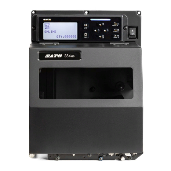
SATO S84ex Configuration Manual
Uhf inlay
Hide thumbs
Also See for S84ex:
- Programming reference manual (452 pages) ,
- Operator's manual (404 pages) ,
- Configuration manual (2 pages)
Advertisement
Table of Contents
UHF Inlay Configuration Guide
Printer Orientation and Label Measurements
Media feed direction
1
: Liner edge to center of chip for Orientation
X
How to check the Configuration Table
NO. Manufacturer
[IC Chip]
Alien
1
Alien
2
Alien
S84-ex UHF Inlay Placement & Configuration Table
This recommendation has been tested successfully at SATO. Results may vary in the actual
customer installation due to overall system tolerances. Validation of functionality in the actual
system is therefore recommended.
In no event shall SATO be liable for any faults arising out of use of or inability to use the product.
In order to successfully configure your S84-ex UHF printer,
you will need the following information about your label.
X
1
I-Mark
Y: Optimum Encoding Position *
S: Minimum Inlay Separation
*Y: Measured from tail edge of I-mark to lead edge of inlay when I-mark sensor is used.
Measured from lead edge of label to lead edge of inlay when gap sensor is used.
Feed Direction affects results, and
is signified by the images in the
following table.
Feed Direction
The arrow in the header of table
indicates the direction in which labels
are output from the printer.
Inlay
Feed Direction
Media feed direction
2
: Liner edge to center of chip for Orientation
X
Position(mm)
Antenna
Region
X
Y
Pitch
Short Pitch 50.7-55.4
1-5
Standard
Short Pitch 50.4-55.4
2-6
Standard
Short Pitch
Standard
—
—
Short Pitch
Standard
—
—
Short Pitch
Standard
Short Pitch
Standard
Select the related
Antenna Pitch according
to your label's "Y" value.
Printer orientation will
affect viable settings.
Power (dBm)
Position(mm)
S
Write Read
X
Y
S
19
22
9
—
—
—
19
22
9
60.4-65.4
1-7
19
—
—
—
—
—
—
—
—
—
—
—
—
First edition: Jan 2015
Q04652900
©2015 SATO CORPORATION
X
2
I-Mark
Power (dBm)
Write Read
—
—
24
12
—
—
—
—
Advertisement
Table of Contents

Subscribe to Our Youtube Channel
Summary of Contents for SATO S84ex
- Page 1 Validation of functionality in the actual system is therefore recommended. In no event shall SATO be liable for any faults arising out of use of or inability to use the product. First edition: Jan 2015 Q04652900 ©2015 SATO CORPORATION...
- Page 2 8-16 57-68 17-23 For inlays not included on this list, please contact your local SATO dealer or sales office. www.satoworldwide.com • Squiggle and Higgs are trademarks or registered trademarks of Alien Technology Corporation in the U.S. and other countries. • Monza is registered trademark of Impinj, Inc.


Need help?
Do you have a question about the S84ex and is the answer not in the manual?
Questions and answers