Table of Contents
Advertisement
Quick Links
Download this manual
See also:
Operating Manual
Advertisement
Table of Contents

Related Manuals for VIA Technologies EPIA-P720


Summary of Contents for VIA Technologies EPIA-P720
- Page 1 EPIA-P720 Pico-ITX Mainboard Revision 1.03 103-11232009-1105...
-
Page 2: Copyright And Trademarks
However, VIA Technologies assumes no responsibility for the use or misuse of the information in this document and for any patent infringements that may arise from the use of this document. -
Page 3: Safety Precautions
Safety Precautions Do’s Always read the safety instructions carefully. Keep this User's Manual for future reference. All cautions and warnings on the equipment should be noted. Keep this equipment away from humidity. Lay this equipment on a reliable flat surface before setting it up. -
Page 4: Box Contents
Box Contents 1 x EPIA-P720 Pico-ITX mainboard 1 x P720-A I/O module board 1 x SATA cable 1 x SATA power cable 1 x DC-In cable 1 x Driver utility CD... -
Page 5: Table Of Contents
Key Components ....................2 VIA Eden ULV 1.0GHz NanoBGA2 Processor ........ 2 VIA VX855 Media System Processor............. 2 Mainboard Specifications ................3 EPIA-P720 Layout ....................4 Top Side ......................4 Bottom Side....................... 5 P720-A I/O Module Layout ................6 Front View......................6 Top View ...................... - Page 6 3 Onboard Jumpers ....................27 Clear CMOS jumper: JM1.................28 LCD Panel Power Selector: JM2............29 LCD Backlight Power Selector: JM3 ............29 4 P720-A I/O Module Installation ..............31 P720-A Installation Procedure..............32 5 BIOS Setup......................35 Entering the BIOS Setup Menu ..............36 Control Keys ......................36 Getting Help ......................37 Main Menu ......................38 AMIBIOS......................38...
- Page 7 General ACPI Configuration ................45 Suspend Mode ....................45 Repost Video on S3 Resume ..............45 Advanced ACPI Configuration ..............46 ACPI Version Features ................46 ACPI APIC Support..................46 AMI OEMB Table..................46 Headless Mode....................46 Chipset ACPI Configuration .................47 USB Device Wakeup Function..............47 APM Configuration...................48 Power Management / APM ..............48 Power Button Mode...................48 Suspend Power Saving Type..............48 Restore on AC / Power Loss ..............48...
- Page 8 Allocate IRQ to PCI VGA................53 Palette Snooping ..................53 PCI IDE BusMaster..................54 Off Board PCI/ISA IDE Card ..............54 IRQ3~15 ......................54 DMA Channel 0~7 ..................54 Reserved Memory Size................54 Boot Settings......................55 Boot Settings Configuration..............55 Boot Device Priority..................55 Boot Settings Configuration.................56 Quick Boot.......................56 Display Logo....................56 AddOn ROM Display Mode..............56 Bootup Num-Lock ..................56 PS/2 Mouse Support...................56...
- Page 9 High Definition Audio................63 Enable Embedded COM................63 PCI Debug Master Mode................63 SMBus Multi-Master..................63 PCI VCC33 Leakage Patch...............63 PCI Delay Transaction ................64 WATCH-DOG ....................64 Exit Options ......................65 Save Changes and Exit ................65 Discard Changes and Exit................65 Discard Changes ..................65 Load Optimal Defaults................65 6 Driver Installation....................67 Driver Utilities.......................68 Getting Started ....................68...
-
Page 11: Product Overview
Product Overview... -
Page 12: Key Components
The VIA EPIA-P720 is an ultra-compact and highly integrated Pico- ITX mainboard and the smallest stand-alone form-factor available today. Through a high level of integration, the Pico-ITX form factor is 75% smaller than the existing Mini-ITX form factor. mainboard enables the creation of an exciting new generation of small, ergonomic, innovative and affordable embedded systems. -
Page 13: Mainboard Specifications
AINBOARD PECIFICATIONS VIA Eden ULV 1.0 GHz NanoBGA2 processor • NanoBGA2 package • 400 MHz Front Side Bus VIA VX855 All-in-One System Processor Chipset Integrated VIA Chrome9 HCM DX9 with MPEG-2/4 Graphics Accelerators One DDR2 800/667 SODIMM slot (up to 2 GB) System Memory One UltraDMA 133/100/66/33 44-pin IDE connector Onboard Storage... -
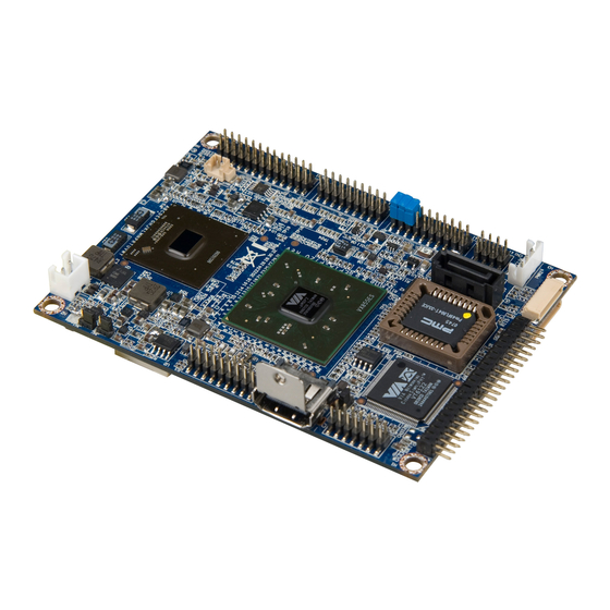
Page 14: Epia-P720 Layout
EPIA-P720 L AYOUT Top Side Symbol Symbol Description Description Symbol Symbol Description Description Symbol Symbol Description Description Symbol Symbol Description Description Front Audio pin header PWR1 DC-In power connector USB and USB Device port PWR2 SATA Power connector pin header... -
Page 15: Bottom Side
Bottom Side Symbol Symbol Symbol Symbol Description Description Description Description Symbol Symbol Symbol Symbol Description Description Description Description BAT1 CMOS Battery connector SODIMM1 DDR2 SODIMM slot LVDS1 1-CH LVDS Panel connector VCP/UART port 1... -
Page 16: P720-A I/O Module Layout
P720-A I/O M ODULE AYOUT The VIA EPIA-P720 Pico-ITX mainboard is bundled with an I/O board (P720-A) to support connections to LAN, VGA and USB. Front View Top View Bottom View Symbol Symbol Description Description Symbol Symbol Description Description VGA1... -
Page 17: Development Kit Accessories
The DC-In power cable provides a means to connect to the power brick. Power Brick The power brick provides a regulated 12V/5A output to power up the EPIA-P720 mainboard. Note: Note: Note: Note: The Power brick is not included in the package of EPIA-P720 and this item should be purchased separately. -
Page 19: Onboard Connectors, Slots And Pin Headers
Onboard Connectors, Slots and Pin Headers This chapter provides you with information about hardware installation procedures. It is recommended to use a grounded wrist strap before handling computer components. Electrostatic discharge (ESD) can damage some components. -
Page 20: Top Side Connectors
ONNECTORS VIA Eden ULV 1.0GHz with a Fanless Heatsink The VIA EPIA-P720 Pico-ITX mainboard is packaged with a standard VIA Eden ULV 1.0GHz NanoBGA2 processor. The processor does not require a heatsink with fan because of it highly power efficient and ultra cool performance. -
Page 21: Dc-In Power Connector: Pwr1
DC-In Power connector: PWR1 EPIA-P720 has an onboard DC-In 2-pin power connector to connect the DC-In power cable. Signal DC In (+12V) Serial ATA Power connector: PWR2 The mainboard supports a 3-pin SATA power connector for SATA power cable. Plug the SATA power cable into the SATA power connector. -
Page 22: Serial Ata Connector: Sata1
Serial ATA connector: SATA1 The current SATA interface allows a data transfer rate of up to 300 MB/s — approximately 225% faster than Ultra DMA parallel ATA. HDMI port connector: HDMI1 The mainboard has a High Definition Multimedia Interface (HDMI) port for connecting to high definition video and digital audio. -
Page 23: Ide Pin Header: Ide1
IDE pin header: IDE1 The mainboard has an Ultra DMA 133/100 controller. You can connect up to two IDE devices in any combination. Signal Signal -IDERST PDD7 PDD8 PDD6 PDD9 PDD5 PDD10 PDD4 PDD11 PDD3 PDD12 PDD0 PDD13 PDD1 PDD14 PDD2 PDD15 PDDREQ... -
Page 24: Ethernet Lan Pin Header: Cn3
Ethernet LAN pin header: CN3 The Ethernet LAN pin header is for connecting to the P720-A I/O module. Signal Signal A3V3GL(+3.3V) +3.3VSUS TXNC TXND TXPC TXPD TXNA TXNB TXPA TXPB LED1 LED2 LINK ACT... -
Page 25: Vga And Usb Pin Header: Vga_Usb1
VGA and USB pin header: VGA_USB1 The VGA and USB pin header is for connecting to the P720-A I/O module. Signal Signal VGA_RED VGA_GREEN VGA_BLUE DDC_DATA DDC_CLK +5VUSB_P VGA_VS VGA_HS +5VSUS USBHP0- USBHP1-/USBDP_D- USBHP0+ USBHP1+/USBDP_D+... -
Page 26: Front Audio Pin Header: Cn1
Front Audio pin header: CN1 This pin header allows you to connect a front audio to the mainboard. Signal Signal LINE IN_R AUD_GND LINE IN_L MIC IN_L LINE OUT_R MIC IN_R LINE OUT_L JACK SENSE... -
Page 27: Usb Pin Header: Cn2
USB pin header: CN2 This 20-pin USB pin header allows you to connect up to four USB2.0 ports. Signal Signal USB VD2+ USB VD3+ USB VD2- USB VD3- +5VSUS +5VSUS USB VD5- USB VD4- USB VD5+ USB VD4+ reserved reserved reserved reserved reserved... -
Page 28: Front Panel And Ps/2 Kbms Pin Header: Cn4
Front Panel and PS/2 KBMS pin header: CN4 This single pin header allows you to connect the power switch, reset switch, power LED, HDD LED, case speaker and two PS/2 ports. Signal Signal +PWR_LED +HD_LED +5VSUS (for LED use) -HD_LED PW_SW SPEAK_BZ RST_SW... -
Page 29: Lpc, Smbus And Digital I/O Pin Header: Cn5
LPC, SMBus and Digital I/O pin header: CN5 This single pin header allows the connection of LPC, SMBus devices and the Digital Input and Output. Signal Signal LAD3 SIOOSC LAD2 LPCCLK LAD1 -LDRQ1 -LFRAME SERIRQ LAD0 - - - - SIOSMI SIOSMI SIOSMI/-PME SIOSMI... -
Page 30: Uart/Vcp Port 2: J1
UART/VCP port 2: J1 UART offers TTL level serial signal for the user to easily convert to support RS232/RS422/RS485. Or, the user may use it as the VCP for Video capture. VCP Signal UART Signal (default) +3.3V/+5V SIN_1 SOUT_1 DCD_1 RI_1 DTR_1 VCPHS... -
Page 31: Bottom Side Connector
OTTOM ONNECTOR UART/VCP port 1: J2 UART offers TTL level serial signal for the user to easily convert to support RS232/RS422/RS485. Or, the user may use it as the VCP for Video capture. VCP Signal UART Signal (default) DVPSPCLK -LPCRST DVPSPD VCPD7 CTS_0... -
Page 32: Lvds Panel Connector: Lvds1
LVDS Panel connector: LVDS1 The single-channel LVDS connector allows you to connect the panel’s LVDS cable directly to support LVDS panel. Signal Signal LVDSD0- LVDSD1- LVDSD0+ LVDSD1+ Panel_VDD LVDSD2- Panel_VDD LVDSD2+ LCD1_DATA LCD1_CLK LVDSCLK+ LVDSCLK- Back Light_VDD Back Light_VDD BL_ENABLE DIMMING DIMMING DIMMING... -
Page 33: External Battery: Bat1
External Battery: BAT1 The mainboard comes with external CMOS battery connector. This 2-pin connector used to connect the external cable battery for CMOS. Signal +3.3VBAT... -
Page 34: Memory Module Installation
Memory Module Installation Memory Slot: SODIMM1 The VIA EPIA-P720 Pico-ITX mainboard has one 200-SODIMM slot for DDR2 667/533 SDRAM memory modules and supports memory sizes up to 2 GB. Available DDR2 SDRAM Configuration Refer to the table below for available DDR2 SDRAM configurations on the mainboard. -
Page 35: Installing The Memory
Installing the memory Step 1 Step 1 Step 1 Step 1 Locate the SODIMM slot in the mainboard and align the notch on the SODIMM with the memory slot. Step Step Step Step 2 2 2 2 Insert the SODIMM module at a 45 degree angle. Then push the SODIMM down until it snaps into the locking mechanism. -
Page 37: Onboard Jumpers
Onboard Jumpers... -
Page 38: Clear Cmos Jumper: Jm1
Clear CMOS jumper: JM1 The onboard CMOS RAM stores system configuration data and has an onboard battery power supply. To reset the CMOS settings, set the jumper on pins 2 and 3 while the system is off. Return the jumper to pins 1 and 2 afterwards. Setting the jumper while the system is on will damage the mainboard. -
Page 39: Lcd Panel Power Selector: Jm2
LCD Panel Power Selector: JM2 This jumper determines the input voltage for the LCD connector. Setting +3.3V (default) LCD Backlight Power Selector: JM3 This jumper determines the input voltage for the LCD backlight inverter. Setting +12V +5V (default) -
Page 41: P720-A I/O Module Installation
P720-A I/O Module Installation... -
Page 42: P720-A Installation Procedure
Step 2 Step 2 Step 2 Step 2 Align the CON1 (VGA & USB board-to-board connector) and CON2 (LAN board-to-board connector) of P720-A I/O module board with the CN3 and VGA_USB1 pin headers to the top side of EPIA-P720 mainboard respectively. - Page 43 Step 3 Step 3 Step 3 Step 3 Then gently press down until the pins on the EPIA-P720 mainboard have been fully inserted into the CON1 and CON2 connectors of the P720-A I/O module board. Step 4 Step 4 Step 4 Step 4 Secure the EPIA-P720-A I/O module with two screws.
-
Page 45: Bios Setup
BIOS Setup This chapter gives a detailed explanation of the BIOS setup functions. -
Page 46: Entering The Bios Setup Menu
BIOS S NTERING THE ETUP Power on the computer and press <Delete Delete> during the beginning Delete Delete of the boot sequence to enter the BIOS setup menu. If you missed the BIOS setup entry point, restart the system and try again. ONTROL Keys Description... -
Page 47: Getting Help
ETTING The BIOS setup program provides a “General Help General Help” screen. You General Help General Help can display this screen from any menu/sub-menu by pressing <F1 F1>. The help screen displays the keys for using and navigating F1 F1 the BIOS setup. -
Page 48: Main Menu
AMIBIOS BIOS version number and related information. Processor CPU information. System Memory Memory size. System Time Use the key “+” or “-” to configure system time. The time format is [Hour : Minute : Second]. System Date Use the key “+” or “-” to configure system Date. The date format is [Day, Month, Date, Year]. -
Page 49: Advanced Settings
DVANCED ETTINGS CPU Configuration IDE Configuration ACPI Configuration APM Configuration Spread Spectrum Configuration USB Configuration... -
Page 50: Cpu Configuration
CPU C ONFIGURATION CMPXCHG8B instruction support Settings: [Enabled, Disabled]... -
Page 51: Ide Configuration
IDE C ONFIGURATION Parallel ATA IDE Controller Settings: [Disabled, Primary] Hard Disk Write Protect Settings: [Disabled, Enabled] IDE Detect Time Out (Sec) Settings: [0, 5, 10, 15, 20, 25, 30, 35] ATA(PI) 80Pin Cable Detection Settings: [Host & Device, Host, Device]... -
Page 52: Ide Drives
IDE D RIVES Primary IDE Master Primary IDE Slave (SATA Device) Type Settings: [Not Installed, Auto, CD/DVD, ARMD] LBA/Large Mode Settings: [Disabled, Auto]... -
Page 53: Block (Multi-Sector Transfer)
Block (Multi-Sector Transfer) Settings: [Disabled, Auto] PIO Mode Settings: [Auto, 0, 1, 2, 3, 4] DMA Mode Settings: [Auto] S.M.A.R.T. Self Monitoring Analysis and Reporting Technology, a monitoring system for hard disks. Settings: [Auto, Disabled, Enabled] 32Bit Data Transfer Settings: [Enabled, Disabled]... -
Page 54: Acpi Settings
ACPI S ETTINGS General ACPI Configuration This menu contains ACPI (Advanced Configuration and Power Management Interface) options. Advanced ACPI Configuration Chipset ACPI Configuration... -
Page 55: General Acpi Configuration
ACPI C ENERAL ONFIGURATION Suspend Mode Select the ACPI state used for system suspend. Settings Description S1(POS) S1/Power On Suspend (POS) is a low power state. In this state, no system context (CPU or chipset) is lost and hardware maintains all system contexts S3(STR) S3/Suspend To RAM (STR) is a power-down state. -
Page 56: Advanced Acpi Configuration
ACPI C DVANCED ONFIGURATION ACPI Version Features To enable RSDP pointers to 64-bit Fixed System Description Tables. Settings: [ACPI v1.0, ACPI v2.0, ACPI v3.0] ACPI APIC Support To include ACPI APIC table pointer to RSDT pointer list. Settings: [Enabled, Disabled] AMI OEMB Table To include OEMB table pointer to R(X)SDT pointer lists. -
Page 57: Chipset Acpi Configuration
ACPI C HIPSET ONFIGURATION USB Device Wakeup Function Settings: [Disabled, Enabled]... -
Page 58: Apm Configuration
APM C ONFIGURATION Power Management / APM Settings: [Disabled, Enabled] Power Button Mode Settings: [On/Off, Standby, Suspend] Suspend Power Saving Type Settings: [C3, S1] Restore on AC / Power Loss The field defines how the system will respond after an AC power loss during system operation. -
Page 59: System Thermal
System Thermal Settings: [Disabled, Enabled] Standby Time Out Settings: [Disabled, 1/2/4/8/10/20/30/40/50/60 minutes] Suspend Time Out Settings: [Disabled, 1/2/4/8/10/20/30/40/50/60 minutes] Hard Disk Time Out (Minute) Settings: [Disabled, 1/2/3/4/5/6/7/8/9/10/11/12/13/14/15 minutes] Green PC Monitor Power State Settings: [Standby, Suspend, Off] Video Power Down Mode Settings: [Disabled, Standby, Suspend] Hard Disk Power Down Mode Settings: [Disabled, Standby, Suspend]... -
Page 60: Resume On Ring
Resume on Ring Settings: [Disabled, Enabled] Resume on PME# Settings: [Disabled, Enabled] Resume On PS/2 KBC Settings: [Disabled, S3, S3/S4/S5] Wake-up Key Settings: [Any Key, Specific Key] Resume on PS/2 Mouse Enable any mouse activity to restore the system from the power saving mode to an active state. -
Page 61: Spread Spectrum Configuration
PREAD PECTRUM ONFIGURATION Spread Spectrum Configuration Settings: [Disabled, 0.1%, 0.2%, 0.3%, 0.4%, 0.5%, 0.6%, 0.7%, 0.8%, 0.9%]... -
Page 62: Usb Configuration
USB C ONFIGURATION USB 1.1 Ports Configuration To enable USB 1.1 host controllers. Settings: [Disabled, USB 2 ports, USB 4 ports, USB 6 ports] USB 2.0 Ports Enable To enable USB 2.0 host controllers. Settings: [Disabled, Enabled] USB Device Mode Enable Settings: [Enabled, Disabled] Legacy USB Support To enable support for legacy USB. -
Page 63: Advanced Pci/Pnp Settings
PCI/P DVANCED ETTINGS Note: Note: Note: Note: This section covers some very technical items and it is strongly recommended to leave the default settings as it is unless you are an experienced user. Clear NVRAM To clear NVRAM during system boot. Settings: [No, Yes] Plug &... -
Page 64: Pci Ide Busmaster
PCI IDE BusMaster Settings: [Disabled, Enabled] Off Board PCI/ISA IDE Card Settings: [Auto, PCI Slot1, PCI Slot2, PCI Slot3, PCI Slot4, PCI Slot5, PCI Slot6] IRQ3~15 Settings: [Available, Reserved] DMA Channel 0~7 Settings: [Available, Reserved] Reserved Memory Size To decide the size of memory block to reserve for legacy ISA devices. -
Page 65: Boot Settings
ETTINGS Boot Settings Configuration Configuration settings during system boot. Boot Device Priority Specifies the boot device priority sequence. -
Page 66: Boot Settings Configuration
ETTINGS ONFIGURATION Quick Boot Settings: [Disabled, Enabled] Display Logo Settings: [Disabled, Enabled] AddOn ROM Display Mode Settings: [Force BIOS, Keep Current] Bootup Num-Lock To select power-on state for Num-Lock. Settings: [Off, On] PS/2 Mouse Support Settings: [Disabled, Enabled, Auto] Wait For ‘F1’ If Error Settings: [Disabled, Enabled] Hit ‘DEL’... -
Page 67: Interrupt 19 Capture
Interrupt 19 Capture Settings: [Disabled, Enabled]... -
Page 68: Boot Device Priority
EVICE RIORITY 1st Boot Device To specifies the boot sequence from the available devices. The available boot devices are detected dynamically according to real situation and variable options will be provided. Settings: [Network: VIA Networking Bootagent, Disabled]... -
Page 69: Security Settings
ECURITY ETTINGS Change Supervisor Password This option is for setting a password for entering BIOS Setup. When a password has been set, a password prompt will be displayed whenever BIOS Setup is run. This prevents an unauthorized person from changing any part of your system configuration. -
Page 70: Advanced Chipset Settings
DVANCED HIPSET ETTINGS Caution: Caution: Caution: Caution: The Advanced Chipset Features menu is used for optimizing the chipset functions. Do not change these settings unless you are familiar with the chipset. North Bridge VIA VX855 Configuration South Bridge VIA VX855 Configuration... -
Page 71: North Bridge Via Vx855 Configuration
VIA VX855 ORTH RIDGE ONFIGURATION Software Reset E2 Issue Settings: [Patch, Escape Patch] Change DCLK using RDCKM Settings: [Program, Escape Program] Dynamic CKE Settings: [Disabled, Enabled] NB Performance Register Settings: [Disabled, Enabled] NB Energy Saving Register Settings: [Disabled, Enabled]... -
Page 72: Onchip Vga Configuration
VGA C ONFIGURATION VGA Frame Buffer Size Settings: [64MB, 128MB, 256MB] CPU Direct Access Frame Buffer Settings: [Disabled, Enabled] Select Display Device Settings: [CRT, LCD, HDMI, CRT+LCD, CRT+HDMI] Panel Type Settings: [02] Dithering Settings: [Disabled, Enabled] Backlight Control Settings: [0%, 25%, 50%, 75%, 100%]... -
Page 73: South Bridge Via Vx855 Configuration
VIA VX855 OUTH RIDGE ONFIGURATION Parallel Channel Enable Settings: [Enabled, Disabled] ISA Master Support Settings: [Support, Not Support] High Definition Audio Settings: [Disabled, Auto] Enable Embedded COM Settings: [Disabled, Enabled] PCI Debug Master Mode Settings: [Disabled, Enabled] SMBus Multi-Master Settings: [Disabled, Enabled] PCI VCC33 Leakage Patch Settings: [Disabled, Enabled]... -
Page 74: Pci Delay Transaction
PCI Delay Transaction Settings: [Disabled, Enabled] WATCH-DOG Settings: [Disabled, Enabled]... -
Page 75: Exit Options
PTIONS Save Changes and Exit Exit system setup after saving the changes, or press “F10”. Discard Changes and Exit Exit system setup without saving any changes, or press “Esc”. Discard Changes Discard changes which have been done so far to any of the setup questions, or press “F7”. -
Page 77: Driver Installation
Driver Installation This chapter gives you brief descriptions of each mainboard driver and application. You must install the VIA chipset drivers first before installing other drivers such as VGA drivers. The applications will only function correctly if the necessary drivers are already installed. -
Page 78: Driver Utilities
RIVER TILITIES Getting Started The VIA EPIA-P720 includes a driver CD that contains the drivers and software for enhancing the performance of the system. The drivers can also be downloaded from http://www.via.com.tw. Note: Note: Note: Note: The driver utilities and software are updated from time to time. -
Page 79: Cd Content
CD C ONTENT VIA 4 in 1 Drivers 4 in 1 Drivers 4 in 1 Drivers 4 in 1 Drivers Contains VIA ATAPI Vendor Support Driver (enables the performance enhancing bus mastering functions on ATA- capable Hard Disk Drives and ensures IDE device compatibility), AGP VxD Driver (provides service routines to your VGA driver and interface directly to hardware, providing fast graphical access), IRQ Routing Miniport...
Need help?
Do you have a question about the EPIA-P720 and is the answer not in the manual?
Questions and answers