
Related Manuals for VIA Technologies VIA SOM-3000


Summary of Contents for VIA Technologies VIA SOM-3000
- Page 1 USER MANUAL VIA SOM-3000 Starter Kit Fanless low-power platform for Edge AI applications with MediaTek Genio 350 quad-core processor 1.04-21032024...
- Page 2 VIA Technologies, Inc. reserves the right the make changes to the products described in this manual at any time without prior notice.
- Page 3 VIA SOM-3000 Starter Kit User Manual Battery Recycling and Disposal • Only use the appropriate battery specified for this product. • Do not re-use, recharge, or reheat an old battery. • Do not attempt to force open the battery. •...
- Page 4 Ordering Information Part Number Description 10GPE20G10020A0 VIA SOM-3000 module with 2.0GHz MediaTek Genio 350 Quad-Core SoC, 16GB eMMC, 2GB LPDDR4 SDRAM, Wi-Fi 5, Bluetooth 5.0 STK-SOM935-00A0 VIA SOM-3000 Starter Kit with SOM-3000 Module + VAB-935 Carrier Board + Accessory Kit...
-
Page 5: Table Of Contents
UART Debug Connector ........................5 I-PEX Connector ............................ 6 Hardware Installation ............................. 7 Installing the VIA SOM-3000 Module on the Carrier Board ..............7 Connecting the Wi-Fi Antenna ......................8 Software and Technical Support ........................9 Android and Yocto Support ........................9 Technical Support and Assistance ...................... - Page 6 VIA SOM-3000 Starter Kit User Manual A.4.26 Power LED ............................ 30 A.4.27 DIO Port ............................30 Appendix B Installing PCIe Mini Card Accessories ................... 31 Installing a PCIe Mini Card into the miniPCIe Slot ................31 Appendix C Connecting LCD Display ........................ 33...
- Page 7 Figure 04: I-PEX connector ............................ 6 Figure 05: VIA SOM-3000 module installation ...................... 7 Figure 06: Securing the VIA SOM-3000 module to the carrier board ..............7 Figure 07: Connecting the Wi-Fi antenna ......................8 Figure 08: VIA VAB-935 carrier board layout (top view) ..................10 Figure 09: VIA VAB-935 carrier board front panel I/O ..................
- Page 8 VIA SOM-3000 Starter Kit User Manual List of Tables Table 01: UART debug connector pinouts ......................5 Table 02: miniPCIe slot pinouts .......................... 13 Table 03: SIM card slot pinouts .......................... 14 Table 04: Battery charger connector pinouts ..................... 15 Table 05: RTC battery connector pinouts ......................
-
Page 9: Product Overview
OCR. Based on the 3.5" SBC 14.6cm x 10.2cm form factor, the VIA SOM-3000 offers a wealth of network connectivity options, including an integrated SIM card slot for LTE/4G, dual-band 802.11ac Wi-Fi, a 10/100Mbps Ethernet port, and Bluetooth 5.0. - Page 10 1 x I/O expansion connector (supports GPIO x 5, I2C x1, UART x1, SPI x1, PWM x 2, ADC x 1 from SOM- 3000, and GPIO x 11 from Expander IC) • 2 x M.2 connectors for VIA SOM-3000 module Front Panel I/O •...
- Page 11 VIA SOM-3000 Starter Kit User Manual Back Panel I/O • 1 x HDMI port • 2 x USB 2.0 ports • 1 x COM port for RS-232 (TX/RX) • 1 x 10/100Mbps Ethernet port • 1 x DC-in jack •...
-
Page 12: Layout Diagram
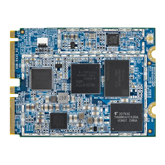
VIA SOM-3000 Starter Kit User Manual 1.3 Layout Diagram PMIC EMMC DPI to HDMI Converter LPDDR4 I-PEX Wi-Fi/BT UART to Debug Port MediaTek Genio 350 SoC Figure 01: VIA SOM-3000 module layout (top view) Figure 02: Dimensions of the VIA SOM-3000 module (top view) -
Page 13: On-Board I/O Connectors
This chapter provides information about the on-board connectors and pin headers of the VIA SOM-3000 module. 2.1 UART Debug Connector The VIA SOM-3000 module is equipped with a UART debug connector labeled ‘J3’. The pinouts of UART debug connector are shown below. Figure 03: UART debug connector... -
Page 14: I-Pex Connector
VIA SOM-3000 Starter Kit User Manual 2.2 I-PEX Connector The VIA SOM-3000 comes with an I-PEX connector labeled ‘J1’ which is used for connecting the Bluetooth and Wi-Fi antenna. The diagram of the I-PEX connector is shown below. Figure 04: I-PEX connector... -
Page 15: Hardware Installation
3.1 Installing the VIA SOM-3000 Module on the Carrier Board Step 1 Align the VIA SOM-3000 module's notch with the notch of the M.2 slot located on the VIA VAB-935 carrier board's top side and insert the VIA SOM-3000 module at a 30° angle. M.2 Slot... -
Page 16: Connecting The Wi-Fi Antenna
VIA SOM-3000 Starter Kit User Manual 3.2 Connecting the Wi-Fi Antenna Step 1 Connect the Wi-Fi Antenna to the I-PEX connector on the VIA SOM-3000 module. Figure 07: Connecting the Wi-Fi antenna... -
Page 17: Software And Technical Support
VIA SOM-3000 Starter Kit User Manual 4. Software and Technical Support 4.1 Android and Yocto Support The VIA SOM-3000 features a complete software evaluation image featuring the Android 12 and Yocto 3.1 operating systems. 4.2 Technical Support and Assistance •... -
Page 18: Appendix Avia Vab-935 Carrier Board Reference
VIA SOM-3000 Starter Kit User Manual Appendix A VIA VAB-935 Carrier Board Reference A.1 Carrier Board I/O MicroSD Power LED Line-out Power Button Micro USB MIC1 MIC0 2x20 Pin I/O Expander Speakers SIM Card Slot MIPI 4-Lane CSI for Rear... -
Page 19: Carrier Board Dimensions
VIA SOM-3000 Starter Kit User Manual MIPI DSI LCD Connector Touch Panel Connector Figure 11: VIA VAB-935 carrier board layout (bottom view) A.2 Carrier Board Dimensions 134.2mm 6.9mm 67.5mm 146mm Figure 12: Dimensions of the VIA VAB-935 carrier board (top view) 120.7mm... -
Page 20: Carrier Board Height Distribution
VIA SOM-3000 Starter Kit User Manual 120.7mm 102.4mm 88.9mm 75.7mm 55.5mm 25.4mm Figure 14: External I/O dimensions of the VIA VAB-935 carrier board (back panel) A.3 Carrier Board Height Distribution 13mm 14mm 16mm 10mm 10mm 13mm Figure 15: Height distribution of the VIA VAB-935 carrier board (top view) ... -
Page 21: Carrier Board On-Board I/O
VIA SOM-3000 Starter Kit User Manual A.4 Carrier Board On-Board I/O A.4.1 miniPCIe Slot The VIA VAB-935 carrier board is equipped with a miniPCIe slot labeled ‘J3’ for wireless networking options such as a 4G module (EC-20/EC-25). The pinouts of the miniPCIe slot are shown below. -
Page 22: Sim Card Slot
VIA SOM-3000 Starter Kit User Manual A.4.2 SIM Card Slot The VIA VAB-935 carrier board comes with a SIM card slot that supports 4G SIM cards. SIM card usage requires that a 4G module is installed in the miniPCIe slot, otherwise the SIM card slot will be disabled. The SIM card slot is designed for use with 4G modules that do not support built-in SIM card slots. -
Page 23: Battery Charger Connector
VIA SOM-3000 Starter Kit User Manual A.4.3 Battery Charger Connector The VIA VAB-935 carrier board is equipped with a battery charger connector labeled ‘J17’ which is used for charging the rechargeable lithium-ion polymer battery and powering the board. The pinouts of the battery charger connector are shown below. -
Page 24: Rtc Battery Connector
VIA SOM-3000 Starter Kit User Manual A.4.4 RTC Battery Connector The VIA VAB-935 carrier board comes with an RTC battery connector labeled ‘BAT1’, and supports 3.0V 240mAh dioxide lithium batteries. It provides power to the MCU to maintain the real time clock while the DC adapter and lithium-ion polymer battery are both absent. -
Page 25: On-Board Mic Connector
VIA SOM-3000 Starter Kit User Manual Signal Signal SPK_LN SPK_RN SPK_LP SPK_RP Table 06: Speaker connector pinouts A.4.6 On-Board MIC Connector The VIA VAB-935 carrier board is equipped with an on-board MIC connector labeled ‘J20’ which is used for collecting the peripheral audio signal. The pinouts of the on-board MIC connector are shown below. -
Page 26: Mcu Upgrade Pin Header
VIA SOM-3000 Starter Kit User Manual A.4.7 MCU Upgrade Pin Header The VIA VAB-935 carrier board is equipped with an MCU upgrade pin header which is used for flashing the MCU firmware on the management IC. The MCU upgrade pin header is labeled as ‘J13’. The pinouts of the MCU upgrade pin header are shown below. -
Page 27: Download Button & Pin
VIA SOM-3000 Starter Kit User Manual Signal Signal Signal Signal RDN3 14 RDP0 RDN3 14 RDP0 RDP3 15 GND RDP3 15 GND 16 DOVDD_1.8V 16 DOVDD_1.8V RDN2 17 AVDD_2.7V RDN2 17 AVDD_2.7V RDP2 18 NC RDP2 18 NC 19 DVDD_1.05V 19 DVDD_1.05V... -
Page 28: I/O Expansion Header
VIA SOM-3000 Starter Kit User Manual A.4.10 I/O Expansion Header The VIA VAB-935 carrier board comes with an I/O expansion header labeled as ‘J24’ which is used for connecting the I²C, SPI, UART, PWM, ADC, and 5 CPU GPIO +11 I/O expander GPIO devices. The I/O expansion header is compatible with the Raspberry Pi 40-pin connector. -
Page 29: Mipi Dsi 4-Lane Connector
VIA SOM-3000 Starter Kit User Manual A.4.11 MIPI DSI 4-Lane Connector The VIA VAB-935 carrier board is equipped with a MIPI DSI 4-lane connector labeled ‘J7’ which is used for connecting the MIPI LCD display. ‘J7’ is placed on the bottom layer of the carrier board. The pinouts of the MIPI DSI connector are shown below. -
Page 30: Touch Panel Connector
VIA SOM-3000 Starter Kit User Manual A.4.12 Touch Panel Connector The VIA VAB-935 carrier board is equipped with a touch panel connector labeled ‘J9’ which is used to connect the Touch panel. The pinouts of the touch panel connector are shown below. -
Page 31: M.2 Connectors
A.4.13.1 M.2 Connectors Pinouts The VIA VAB-935 carrier board comes with two M.2 connectors labeled ‘J1’ and ‘J2’. The M.2 connectors are used for connecting the VIA SOM-3000 module. The pinouts of the M.2 connectors are shown below. Figure 29: M.2 connectors... -
Page 32: Figure 30: M.2 Connector Placement - Carrier Board External I/O
VIA SOM-3000 Starter Kit User Manual 45 CSI0B_L0P 46 DSI_CLK_N 45 TX_CH1_M 46 MCU_WDI 47 GND 48 GND 47 GND 48 SYSRSTB 49 CSI0B_L1N 50 DSI_D2_N 49 TX_CH0_P 50 MCU_STATUS 51 CSI0B_L1P 52 DSI_D2_P 51 TX_CH0_M 52 KPCOL0 53 GND... -
Page 33: Hdmi® Port
VIA SOM-3000 Starter Kit User Manual A.4.14 HDMI® Port The VIA VAB-935 carrier board is equipped with one HDMI port on the back panel. The HDMI port Type-A receptacle connector provides connection to High Definition video and digital audio using a single cable. The pinouts of the HDMI port are shown below. -
Page 34: 10/100Mbps Ethernet Port
VIA SOM-3000 Starter Kit User Manual A.4.16 10/100Mbps Ethernet Port The VIA VAB-935 carrier board comes with a 10/100Mbps Ethernet port on the back panel which uses an 8 Position and 8 Contact (8P8C) receptacle connector commonly known as RJ-45. It is fully compliant with the IEEE 802.3 (10BASE-T) and 802.3u (100BASE-TX) standards. -
Page 35: Ir Receiver
VIA SOM-3000 Starter Kit User Manual A.4.18 IR Receiver The VIA VAB-935 carrier board comes with an IR receiver located on the rear I/O panel. The IR receiver is used for receiving IR signals from infrared remote controllers. The diagram of the IR receiver is shown below. -
Page 36: Micro Usb 2.0 Port
VIA SOM-3000 Starter Kit User Manual A.4.21 Micro USB 2.0 Port The VIA VAB-935 carrier board is equipped with a Micro USB 2.0 port on the front panel. The Micro USB 2.0 port is used for downloading the OS image. The pinouts of the Micro USB 2.0 port are shown below. -
Page 37: Power Button
VIA SOM-3000 Starter Kit User Manual A.4.24 Power Button The VIA VAB-935 carrier board comes with a power button located on the front I/O panel. The power button can support two functions: Power On/Off and System Suspend/Resume. The diagram of the power button is shown below. -
Page 38: Power Led
VIA SOM-3000 Starter Kit User Manual A.4.26 Power LED The VIA VAB-935 carrier board is equipped with a Power LED on the front I/O panel. The Power LED is used to indicate power status. The diagram of the Power LED is shown below. -
Page 39: Appendix B Installing Pcie Mini Card Accessories
VIA SOM-3000 Starter Kit User Manual Appendix B Installing PCIe Mini Card Accessories This chapter provides you with information on how to install a PCIe Mini Card into the miniPCIe slot on the VIA VAB-935 carrier board. It is recommended to use a grounded wrist strap before handling computer components. -
Page 40: Figure 46: Securing The Pcie Mini Card
VIA SOM-3000 Starter Kit User Manual Step 2 Once the PCIe Mini Card has been fully inserted, push down the module until the screw holes align with the standoff holes and then secure the module with two screws provided with the PCIe Mini Card accessory. -
Page 41: Appendix C Connecting Lcd Display
VIA SOM-3000 Starter Kit User Manual Appendix C Connecting LCD Display This chapter provides you with information on how to connect the 10.1” TFT-LCD display to the VIA VAB-935 carrier board. C.1 Connecting the TFT-LCD Display Step 1 Attach the 39-pin FFC cable of the MIPI LCD display to the MIPI DSI connector labeled ‘J7’ on the VIA VAB-935 carrier board. - Page 42 Taiwan Headquarters Japan China 1F, 531 Zhong-zheng Road, 940 Mission Court 3-15-7 Ebisu MT Bldg. 6F, Tsinghua Science Park Bldg. 7 Xindian Dist., New Taipei City 231 Fremont, CA 94539, Higashi, Shibuya-ku No. 1 Zongguancun East Road, Taiwan Tokyo 150-0011 Haidian Dist., Beijing, 100084 Japan China...
Need help?
Do you have a question about the VIA SOM-3000 and is the answer not in the manual?
Questions and answers