VIA Technologies ARTiGO A820 User Manual
Ultra slim fanless system with arm based board
Hide thumbs
Also See for ARTiGO A820:
- User manual (43 pages) ,
- Quick start manual (28 pages) ,
- Development manual (10 pages)
Table of Contents
Advertisement
Quick Links
Advertisement
Table of Contents

Related Manuals for VIA Technologies ARTiGO A820


Summary of Contents for VIA Technologies ARTiGO A820
- Page 2 USER MANUAL ARTiGO A820 Ultra Slim Fanless System with ARM based board 1.00-02262016-111000...
- Page 3 The information and product specifications within this document are subject to change at any time, without notice and without obligation to notify any person of such change. VIA Technologies, Inc. reserves the right the make changes to the products described in this manual at any time without prior notice.
- Page 4 Battery Recycling and Disposal Only use the appropriate battery specified for this product. Do not re-use, recharge, or reheat an old battery. Do not attempt to force open the battery. Do not discard used batteries with regular trash. Discard used batteries according to local regulations. Safety Precautions Always read the safety instructions carefully.
- Page 5 3D10A1 3D10A1 ARTiGO A820 system with Freescale i.MX6 Dual Lite ARM Cortex-A9 Core 1.0GHz, 4GB eMMC Flash, 1GB DDR3 SDRAM, 3 x USB 2.0, 1 x COM, 1 x DIO, 2 x LAN, 1 x HDMI, 1 x DC-In jack, 1 x Micro SD card...
-
Page 6: Table Of Contents
ARTiGO A820 User Manual ARTiGO A820 User Manual ARTiGO A820 User Manual ARTiGO A820 User Manual Table of Contents 1. 1. 1. 1. Product Overview Product Overview ........................................ 1 1 1 1 Product Overview Product Overview ........ - Page 7 ARTiGO A820 User Manual ARTiGO A820 User Manual ARTiGO A820 User Manual ARTiGO A820 User Manual 3.4. COM Debug connector ................21 4. 4. 4. 4. Hardware Installation Hardware Installation Hardware Installation Hardware Installation ..............................................
- Page 8 ARTiGO A820 User Manual ARTiGO A820 User Manual ARTiGO A820 User Manual ARTiGO A820 User Manual Lists of Figures Figure 1: Front panel layout.................... 6 Figure 2: Rear panel layout ..................... 6 Figure 3: Left side panel layout..................6 Figure 4: Front side view dimension ................7 Figure 5: Left side view dimension ................
- Page 9 Figure 37: Securing the top cover ................33 Figure 38: Installing the rubber feet................34 Figure 39: Installing the VESA bracket ............... 35 Figure 40: Installing the VESA plate ................36 Figure 41: Installing the ARTiGO A820 system to the VESA plate ..... 37 viii...
- Page 10 ARTiGO A820 User Manual ARTiGO A820 User Manual ARTiGO A820 User Manual ARTiGO A820 User Manual Lists of Tables Table 1: USB 2.0 ports pinout ..................9 Table 2: DIO connector pinout..................10 Table 3: COM connector pinout ................. 11 Table 4: DC-In jack pinout ....................
-
Page 11: Product Overview Product Overview
1.1.2. Ultra Slim and Space Saving The ARTiGO A820 has an ultra slim chassis, designed to save space that makes it suitable to install in space critical environment and to ensure maximum reliability. Its chassis design has a robust aluminum alloy top cover and steel... -
Page 12: Optimize Integration With Multiple I/O Access
Front, rear I/O and bottom access enable the ARTiGO A820 to easily support various applications as well as for easy integration and quick setup. 1.1.4. Storage Expansion ARTiGO A820 has an onboard 4GB eMMC flash storage and a Micro SD card slot for expandable storage. 1.1.5. Mounting Solution The ARTiGO A820 supports multiple methods for mounting;... -
Page 13: Product Specifications
ARTiGO A820 User Manual ARTiGO A820 User Manual ARTiGO A820 User Manual ARTiGO A820 User Manual 1.2. Product Specifications Processor Processor Processor Processor Freescale i.MX 6Dual Lite ARM Cortex-A9 @ 1.0 GHz System Memory System Memory System Memory System Memory 1GB DDR3-1066 SDRAM using 128M x 16 memory devices ... - Page 14 ARTiGO A820 User Manual ARTiGO A820 User Manual ARTiGO A820 User Manual ARTiGO A820 User Manual I/O coastline ports and connectors I/O coastline ports and connectors I/O coastline I/O coastline ports and connectors ports and connectors Front Panel I/O Front Panel I/O...
- Page 15 ARTiGO A820 User Manual ARTiGO A820 User Manual ARTiGO A820 User Manual ARTiGO A820 User Manual System Dimens System Dimens System Dimens System Dimension (L x W x H) ion (L x W x H) ion (L x W x H) ion (L x W x H) ...
-
Page 16: Panel Layout
ARTiGO A820 User Manual ARTiGO A820 User Manual ARTiGO A820 User Manual ARTiGO A820 User Manual 1.3. Panel Layout Figure Figure 1 1 1 1 : Front panel layout : Front panel layout Figure Figure : Front panel layout : Front panel layout... -
Page 17: Dimensions
ARTiGO A820 User Manual ARTiGO A820 User Manual ARTiGO A820 User Manual ARTiGO A820 User Manual 1.4. Dimensions Figure Figure Figure Figure 4 4 4 4 : Front side view dimension : Front side view dimension : Front side view dimension... -
Page 18: External I/O Pin Descriptions And Functionality
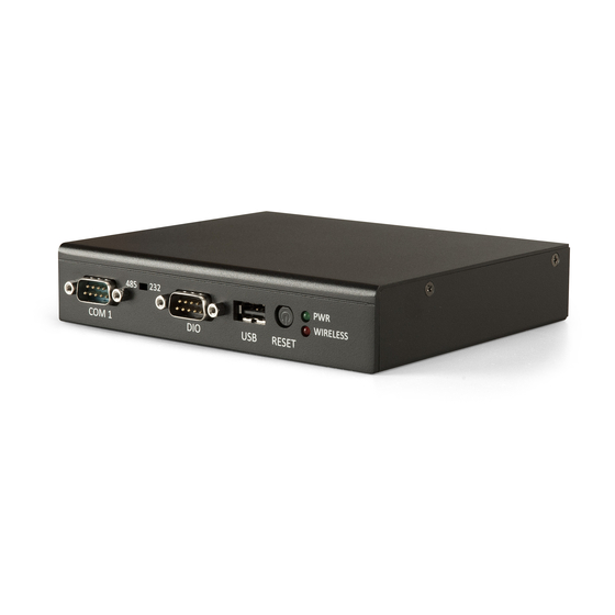
Functionality and Functionality and Functionality The ARTiGO A820 has a wide selection of interfaces. It includes a selection of frequently used ports/connectors as part of the external I/O. 2.1. LED indicator There are two LEDs on the front panel that indicates the status of the system and wireless connectivity: Power LED flashes in green and indicates the system’s power status. -
Page 19: Usb 2.0 Port
ARTiGO A820 User Manual 2.3. USB 2.0 port The ARTiGO A820 provides three USB 2.0 ports, each USB port gives complete Plug and Play and hot swap capability for external devices. The USB interface complies with USB UHCI, Rev. 2.0. The pinout of the USB 2.0 port is shown below. -
Page 20: Dio Connector
ARTiGO A820 User Manual 2.4. DIO connector The ARTiGO A820 system is equipped with one 8-bit Digital I/O connector which offers Digital I/O communication interface. The Digital I/O default settings supports up to eight GPIO signals. The pinout of the Digital I/O connector is shown below. -
Page 21: Com Connector
ARTiGO A820 User Manual ARTiGO A820 User Manual ARTiGO A820 User Manual ARTiGO A820 User Manual 2.5. COM connector The integrated 9-pin COM connector (COM 1) uses a male DE-9 connector located on the front panel. The COM connector can be configured to operate in RS-232 or RS-485 mode. -
Page 22: Com Mode Select Switch
The switch is small and only accessible by thin object. Use a pin or end of a paper clip to access the switch. 2.7. DC-In jack The ARTiGO A820 comes with a DC-In jack on the rear panel that carries 5V external power input. Figure... -
Page 23: Lan Ports
ARTiGO A820 User Manual 2.8. LAN ports The ARTiGO A820 is equipped with two LAN ports that support high speed transmission: Gigabit Ethernet LAN port and Fast Ethernet LAN port. Both LAN ports are located on the rear panel, and using 8 Position 8 Contact (8P8C) receptacle connector (commonly referred to as RJ-45) with LED indicators to show its connection and speed status. - Page 24 ARTiGO A820 User Manual ARTiGO A820 User Manual ARTiGO A820 User Manual ARTiGO A820 User Manual Link LED Link LED Link LED Link LED Active LED Active LED Active LED Active LED (Left LED on RJ (Left LED on RJ- - - - 45 port)
-
Page 25: Fast Ethernet Lan Port
ARTiGO A820 User Manual ARTiGO A820 User Manual ARTiGO A820 User Manual ARTiGO A820 User Manual 2.8.2. Fast Ethernet LAN port The Fast Ethernet port is fully compliant with IEEE 802.3 (10Base-T), (100Base- TX), and (100Base-FX) standards. The Fast Ethernet LAN port is controlled by Fast Ethernet module through onboard USB pin header interface. -
Page 26: Hdmi
ARTiGO A820 User Manual ARTiGO A820 User Manual ® 2.9. HDMI port ® The ARTiGO A820 has a (19-pin) HDMI port located on the rear panel. The ® ® HDMI port uses an HDMI port Type A receptacle connector defined in ®... -
Page 27: Onboard I/O
ARTiGO A820 system’s mainboard. 3.1. Mini PCIe slot The ARTiGO A820 is equipped with one Mini PCIe slot for wireless networking option such as WPAN/WWAN module/card. The Mini PCIe slot is compatible with mini PCIe 2.0 modules/cards that has full-length or half length in size. - Page 28 ARTiGO A820 User Manual ARTiGO A820 User Manual ARTiGO A820 User Manual ARTiGO A820 User Manual PCIe_CRXM MPCIE_3V3 PCIe_CRXP VCC15 PCIe_SMB_CLK PCIe_CTXM PCIe_SMB_DATA PCIe_CTXP PCIE_USB_DM PCIE_USB_DP MPCIE_3V3 MPCIE_3V3 LED_WWAN_B LED_WLAN_B JTAG_nTRST LED_WPAN_B JTAG_nSRST VCC15 MPCIE_3V3 Table Table 10 10: Mini PCIe slot pinout...
-
Page 29: Micro Sd Card Slot
ARTiGO A820 User Manual 3.2. Micro SD Card slot The ARTiGO A820 comes with a Micro SD card slot located on the bottom side of the chassis. Micro SD card slot offers expandable storage of Micro SD card memory up to 32GB capacity. -
Page 30: Micro Sd / Spi Boot Select Switch
ARTiGO A820 User Manual 3.3. Micro SD / SPI Boot Select switch The ARTiGO A820 is equipped with onboard boot select switch which allows users to select boot device from Micro SD and SPI. The switch is labeled as “SW2”. The default switch position is set to Micro SD. -
Page 31: Com Debug Connector
ARTiGO A820 User Manual 3.4. COM Debug connector The ARTiGO A820 is equipped with onboard COM debug connector on the bottom side of the chassis. The onboard COM debug connector is used to attach COM debug cable for debugging purposes. -
Page 32: Hardware Installation
ARTiGO A820 User Manual ARTiGO A820 User Manual ARTiGO A820 User Manual ARTiGO A820 User Manual 4. 4. 4. 4. Hardware Installation Hardware Installation Hardware Installation Hardware Installation This chapter provides information about hardware installation procedures. It is recommended to use a grounded wrist strap before handling computer components. - Page 33 ARTiGO A820 User Manual ARTiGO A820 User Manual ARTiGO A820 User Manual ARTiGO A820 User Manual Step 3 Step 3 Step 3 Step 3 Gently insert the Micro SD card into the card slot with the label side facing down then press the card until it locks into place.
-
Page 34: Installing The Wpan/Wwan Mini Pcie Module And Antenna
ARTiGO A820 User Manual ARTiGO A820 User Manual ARTiGO A820 User Manual ARTiGO A820 User Manual 4.2. Installing the WPAN/WWAN mini PCIe module and antenna Step 1 Step 1 Step 1 Step 1 Align the notch on the module (WPAN/WWAN) with the notch on the mini PCIe slot then insert the module at a 30°... - Page 35 ARTiGO A820 User Manual ARTiGO A820 User Manual ARTiGO A820 User Manual ARTiGO A820 User Manual Figure Figure Figure Figure 25 25 25 25: Securing WPAN/WWAN mini PCIe (half size) module : Securing WPAN/WWAN mini PCIe (half size) module : Securing WPAN/WWAN mini PCIe (half size) module...
- Page 36 ARTiGO A820 User Manual ARTiGO A820 User Manual ARTiGO A820 User Manual ARTiGO A820 User Manual Step 4 Step 4 Step 4 Step 4 Slide the top cover horizontally to disengage it from the chassis then pull up to remove the top cover.
- Page 37 ARTiGO A820 User Manual ARTiGO A820 User Manual ARTiGO A820 User Manual ARTiGO A820 User Manual Step 6 Step 6 Step 6 Step 6 Insert the WPAN/WLAN port connector into the antenna hole from the inside of the chassis. Insert the washer, fasten it with the nut and install the external antenna.
- Page 38 ARTiGO A820 User Manual ARTiGO A820 User Manual ARTiGO A820 User Manual ARTiGO A820 User Manual Step 7 Step 7 Step 7 Step 7 Gently connect the mini coaxial cable of WPAN/WWAN port connector to the mini RF connector on the WPAN/WWAN mini PCIe module.
-
Page 39: Installing The Wlan Usb Module (Optional)
ARTiGO A820 User Manual ARTiGO A820 User Manual ARTiGO A820 User Manual ARTiGO A820 User Manual 4.3. Installing the WLAN USB module (optional) Step 1 Step 1 Step 1 Step 1 Install the WLAN USB module (VNT9271) on standoff holes and secure it with two screws. - Page 40 ARTiGO A820 User Manual ARTiGO A820 User Manual ARTiGO A820 User Manual ARTiGO A820 User Manual Step 3 Step 3 Step 3 Step 3 Insert the WLAN USB port connector into the antenna hole from the inside. Insert the washer, fasten it with the nut and install the external antenna. Gently connect the mini coaxial cable of the WLAN port connector to the mini RF connector on the WLAN USB module (VNT9271).
-
Page 41: Connecting Com Debug Cable
ARTiGO A820 User Manual ARTiGO A820 User Manual ARTiGO A820 User Manual ARTiGO A820 User Manual 4.4. Connecting COM debug cable Step 1 Step 1 Step 1 Step 1 Remove the bottom access cover. Step 2 Step 2 Step 2 Step 2 Gently attach the COM debug cable onto the onboard COM debug connector. -
Page 42: Reinstalling The Top Cover
ARTiGO A820 User Manual ARTiGO A820 User Manual ARTiGO A820 User Manual ARTiGO A820 User Manual 4.5. Reinstalling the top cover Step 1 Step 1 Step 1 Step 1 Mount the top cover and then gently slide/push backward the top cover until it completely covers the top side of the chassis. - Page 43 ARTiGO A820 User Manual ARTiGO A820 User Manual ARTiGO A820 User Manual ARTiGO A820 User Manual Step 2 Step 2 Step 2 Step 2 Once the top cover has been put in place, secure the top cover with six screws. Then reinstall four hex stand screws of the COM connectors.
-
Page 44: Installing The Rubber Feet (Optional)
ARTiGO A820 User Manual ARTiGO A820 User Manual ARTiGO A820 User Manual ARTiGO A820 User Manual 4.6. Installing the Rubber feet (optional) Step Step Step Step 1 1 1 1 Locate the designated areas for rubber feet on the bottom side of the chassis. -
Page 45: Installing The Vesa Mounting Kit (Optional)
Step 1 Step 1 Step 1 Step 1 Attach the VESA bracket on the back of the ARTiGO A820 using four M4 x 6mm screws. Figure Figure 39 39: Installing the VESA bracket : Installing the VESA bracket... - Page 46 ARTiGO A820 User Manual ARTiGO A820 User Manual ARTiGO A820 User Manual ARTiGO A820 User Manual Step 2 Step 2 Step 2 Step 2 Align the VESA mounting hole of the VESA plate to the VESA hole on the back of the monitor.
- Page 47 Step 4 Step 4 Step 4 Step 4 Slide the ARTiGO A820 system into the VESA plate. Then connect all the necessary cables on the rear panel of the system. Figure Figure 41 41: Installing the ARTiGO A820 system to the VESA plate...
-
Page 48: Software And Technical Supports Software And Technical Supports
Supports Supports Supports Supports 5.1. Linux Support The VIA ARTiGO A820 mainboard is highly compatible with Linux Kernel 3.0.35. 5.1.1. Driver Installation Support and drivers are provided through various methods including: Drivers provided by VIA Using a driver built into a distribution package Visiting www.viatech.com...
Need help?
Do you have a question about the ARTiGO A820 and is the answer not in the manual?
Questions and answers