
Related Manuals for Analog Devices WVGA/LCD EI3


Summary of Contents for Analog Devices WVGA/LCD EI3
- Page 1 WVGA/LCD EI3 Extender Board Manual an EZ-Extender product ® Revision 1.0, April 2012 Part Number 82-000254-01 Analog Devices, Inc. One Technology Way Norwood, Mass. 02062-9106...
- Page 2 Analog Devices, Inc. Printed in the USA. Disclaimer Analog Devices, Inc. reserves the right to change this product without prior notice. Information furnished by Analog Devices is believed to be accurate and reliable. However, no responsibility is assumed by Analog Devices for its use;...
-
Page 3: Regulatory Compliance
Regulatory Compliance The WVGA/LCD EI3 Extender Board is designed to be used solely in a laboratory environment. The board is not intended for use as a consumer end product or as a portion of a consumer end product. The board is an open system design which does not include a shielded enclosure and there- fore may cause interference to other electrical devices in close proximity. -
Page 5: Table Of Contents
What’s New in This Manual ............. x Technical Support ................x Supported Processors ............... xi Product Information ............... xi Analog Devices Web Site ............xii EngineerZone ................xii Related Documents ............... xiii USING WVGA/LCD EI3 EXTENDER BOARD Package Contents ................1-2 Supported Operating Systems ............ - Page 6 REFERENCE System Architecture ..............2-2 Software-Controlled Switches (SoftConfig) ........2-3 Overview of SoftConfig ............2-3 Programming SoftConfig on the WVGA/LCD EI3 Extender Board ............... 2-7 LCD SPI Chip Select ............2-13 PPICLK_DIR Select ............. 2-13 LCD Mode Select ..............2-13 AD7879 PENIRQ Signal ............
- Page 7 Expansion Interface III (EI3) Connectors (P1–2) ....2-17 Power Connector (P4) ............2-17 LCD Connector (P5) ............. 2-18 Power LED (LED1) ..............2-18 WVGA/LCD EI3 EXTENDER BOARD BILL OF MATERIALS WVGA/LCD EI3 EXTENDER BOARD SCHEMATIC Title Page ..................B-1 EI3 Connectors/GPIO Extender ........... B-2 EI3 Unused Connectors ...............
- Page 8 WVGA/LCD EI3 Extender Board Manual...
-
Page 9: Preface
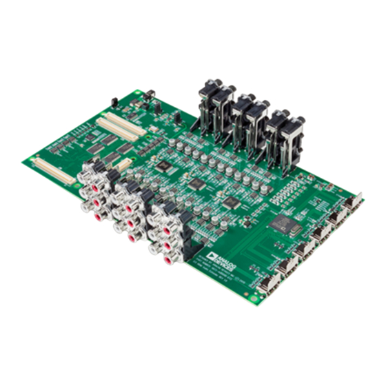
To learn more about Analog Devices development software, go to http://www.analog.com/processors/tools/ Product Overview The WVGA/LCD EI3 Extender Board is a separately sold daughter board that plugs onto the IE3 of an EZ-KIT Lite/EZ-Board evaluation system. The extender board aids the design and prototyping phases of embedded processor-targeted applications. -
Page 10: Purpose Of This Manual
• No power supply required: derives power from the EZ-KIT Lite/EZ-Board • CE certified Purpose of This Manual The WVGA/LCD EI3 Extender Board Manual provides instructions for installing the product hardware (board). The text describes operation and configuration of the board components and provides guidelines for run- viii... -
Page 11: Intended Audience
Preface ning your own code on the WVGA/LCD EI3 Extender Board. Finally, a schematic and a bill of materials are provided for reference. Intended Audience The primary audience for this manual is a programmer who is familiar with Analog Devices processors. This manual assumes that the audience has a working knowledge of the appropriate processor architecture, instruction set, and C/C++ programming languages. -
Page 12: What's New In This Manual
B-1 Provides all of the circuits on the extender board. What’s New in This Manual This is the first revision of the WVGA/LCD EI3 Extender Board Manual. Technical Support You can reach Analog Devices processors and DSP technical support in the following ways: •... -
Page 13: Supported Processors
P.O. Box 9106 Norwood, MA 02062-9106 Supported Processors This extender board supports EZ-KIT Lite/EZ-Board evaluation systems with IE3. Product Information Product information can be obtained from the Analog Devices Web site and CCES online help system. WVGA/LCD EI3 Extender Board Manual... -
Page 14: Analog Devices Web Site
Your user name is your e-mail address. EngineerZone EngineerZone is a technical support forum from Analog Devices. It allows you direct access to ADI technical support engineers. You can search FAQs and technical information to get quick answers to your embedded processing and DSP design questions. -
Page 15: Related Documents
Library Manual for Blackfin Processors mands for Blackfin processors. CrossCore Embedded Studio Linker and Utilities Description of the linker functions and com- Manual mands. CrossCore Embedded Studio Loader and Utilities Description of the loader/splitter functions and Manual commands. WVGA/LCD EI3 Extender Board Manual xiii... - Page 16 Related Documents WVGA/LCD EI3 Extender Board Manual...
-
Page 17: Extender Board
1 USING WVGA/LCD EI3 EXTENDER BOARD This chapter provides the setup procedure for the WVGA/LCD EI3 Extender Board and evaluation board and describes the interfaces the extender supports. The information is presented in the following order. • “Package Contents” on page 1-2 •... -
Page 18: Package Contents
Package Contents Package Contents Your WVGA/LCD EI3 Extender Board package contains the following items. • WVGA/LCD EI3 extender board • A bag containing hardware for securing the extender board onto the EZ-KIT Lite/EZ-Board • Release notes containing information about the product download Contact the vendor where you purchased your extender board or contact Analog Devices, Inc. -
Page 19: System Requirements
Using WVGA/LCD EI3 Extender Board System Requirements Verify that your PC has these minimum requirements for the CCES installation: • 2 GHz single-core processor • 1 GB RAM • 8 GB available disk space • One open USB port ... -
Page 20: Lcd
CCES with the product BSP. Refer to the EZ-KIT Lite/EZ-Board manual for instructions. The WVGA/LCD EI3 Extender Board is shipped with a NEC 4.1 inch WVGA (800 x 480) liquid crystal display (LCD) with backlight. All of the LCD data, touch screen pins, and power pins connect to the display via a single connector ( ). -
Page 21: Lcd Touch Controller (Ad7879)
Using WVGA/LCD EI3 Extender Board LCD Touch Controller (AD7879) The WVGA/LCD EI3 Extender Board is equipped with an Analog Devices resistive touch controller (AD7879). The AD7879 controller is connected to the LCD touch screen via four pins (X+, X-, Y+, Y-). You can access the controller via the SPI of the processor. -
Page 22: Digital Accelerometer (Adxl345)
An example program demonstrating capabilities of the touch controller is available by installing the product BSP. Digital Accelerometer (ADXL345) The WVGA/LCD EI3 Extender Board is equipped with an Analog Devices 3-axis accelerometer (ADXL345) with high-resolution (13-bit) measurement at up to +/- 16g. Digital output data is formatted as 16-bit twos complement and accessible through SPI or TWI. -
Page 23: Expansion Interface Iii
The EI3 implemented on the WVGA/LCD EI3 Extender Board contains the PPI, SPI, TWI and GPIO ports. These signals are used for the periph- erals on the extender. Signals that are not used on the extender are passed through to two connectors on the bottom side of the board ( and can be used for stacking another EI3 extender board. -
Page 24: Board Design Database
Board Design Database file containing all of the electronic information required for the .zip design, layout, fabrication and assembly of the product is available for download from the Analog Devices board design database at: http://www.analog.com/en/processors-dsp/blackfin/proces- sors/board-design-database/resources/index.html WVGA/LCD EI3 Extender Board Manual... -
Page 25: Wvga/Lcd Ei3 Extender Board Hardware Reference
2 WVGA/LCD EI3 EXTENDER BOARD HARDWARE REFERENCE This chapter describes the hardware design of the WVGA/LCD EI3 Extender Board. The following topics are covered. • “System Architecture” on page 2-2 Describes the board’s configuration and explains how the board components interface with the processor. -
Page 26: System Architecture
System Architecture System Architecture A block diagram of the WVGA/LCD EI3 Extender Board is shown in Figure 2-1. EPPI GPIO Back 3.3V Light Bus Transceiver Voltage Regulation ADP1613 ADP1715 Soft Flash Config (Internal Power XC2C256 Use Only) Soft Soft Soft... -
Page 27: Software-Controlled Switches (Softconfig)
WVGA/LCD EI3 Extender Board Hardware Reference Software-Controlled Switches (SoftConfig) On the WVGA/LCD EI3 Extender Board, all of the traditional mechani- cal switches and jumpers have been replaced by I C software-controlled switches. Refer to any file found in the installation direc- SoftConfig*.c... - Page 28 The default is shown by black boxes located closer to the label of the switches. In order to disconnect these switches, physically move the switch to the position. WVGA/LCD EI3 Extender Board Manual...
- Page 29 WVGA/LCD EI3 Extender Board Hardware Reference Figure 2-3. Example of Mechanical Switch Equivalent to Figure 2-2 Figure 2-4 shows a bus switch example, reference designator UC (Pericom PI3LVD512ZHE), selecting between lettered functionality and numbered functionality. The signals on the left side are multiplexed signals with naming convention .
- Page 30 Software-Controlled Switches (SoftConfig) Figure 2-4. Example of Bus Switch WVGA/LCD EI3 Extender Board Manual...
-
Page 31: Programming Softconfig On The Wvga/Lcd Ei3 Extender Board
Figure 2-5. Example of Mechanical Switch Equivalent to Figure 2-4 Programming SoftConfig on the WVGA/LCD EI3 Extender Board On the WVGA/LCD EI3 Extender Board, a single Xilinx XC2C256 com- plex programmable logic device (CPLD) controls individual and WVGA/LCD EI3 Extender Board Manual... - Page 32 IODIR Register IODIR Register Address Value to be Written to Program Signals as Outputs IODIRA 0x02 IODIRB 0x04 IODIRC 0x06 IODIRD 0x08 IODIRE 0x0a WVGA/LCD EI3 Extender Board Manual...
- Page 33 The code that programs the soft switches is located in the file in each example. SoftConfig_LCD.c Page 2 of “WVGA/LCD EI3 Extender Board Schematic” on page B-1 shows how the GPIO expander is connected to the board’s ICs. are 24-bit bus switches. The switches select how the LCD module U14–16 is connected to the processor.
- Page 34 Default Connected ~CAP_TOUCH_INT_GPIO0 Cap touch interrupt ~CAP_TOUCH_INT_GPI01 Cap touch interrupt ~CAP_TOUCH_INT_GPIO2 Cap touch interrupt ~CAP_TOUCH_INT_GPIO3 Cap touch interrupt Cap touch interrupt ~CAP_TOUCH_INT_GPIO4 Cap touch interrupt ~CAP_TOUCH_INT_GPIO5 ~CAP_TOUCH_INT_GPIO6 Cap touch interrupt ~CAP_TOUCH_INT_GPIO7 Cap touch interrupt 2-10 WVGA/LCD EI3 Extender Board Manual...
- Page 35 WVGA/LCD EI3 Extender Board Hardware Reference Table 2-3. Output Signals of GPIO Expander (U10 Port C) Signal Name Description Component Default Connected Accelerometer interrupt 1 ~ADXL_INT1_GPIO0 Accelerometer interrupt 1 ~ADXL_INT1_GPIO1 Accelerometer interrupt 1 ~ADXL_INT1_GPIO2 Accelerometer interrupt 1 ~ADXL_INT1_GPIO3 Accelerometer interrupt 1...
- Page 36 Accelerometer SPI chip select ~ADXL_SPICS_SPICSA Accelerometer SPI chip select ~ADXL_SPICS_SPICSB Accelerometer SPI chip select ~ADXL_SPICS_SPICSC Enable SPI on accelerometer ~ADXL_SPI_MODE Enable TWI on accelerometer ADXL_TWI_MODE 24-bit LCD mode ~24_BIT_LCD_MODE 18-bit LCD mode ~18_BIT_LCD_MODE 16-bit LCD mode ~16_BIT_LCD_MODE 2-12 WVGA/LCD EI3 Extender Board Manual...
-
Page 37: Lcd Spi Chip Select
WVGA/LCD EI3 Extender Board Hardware Reference LCD SPI Chip Select The LCD switch connects the chip select pin of the serial peripheral SPICS interconnect interface (SPI) of the LCD to one of three SPI select pins of the processor. ports... -
Page 38: Ad7879 Spi Chip Select
) is driven low to enable the ADXL345_SPI_MODE GPF3 bus switch. To configure the ADXL345 accelerometer for operating in TWI mode, signal ( port ) is driven high to enable the ADXL345_TWI_MODE GPF4 TWI switch. 2-14 WVGA/LCD EI3 Extender Board Manual... -
Page 39: Adxl345 Spi Chip Select
WVGA/LCD EI3 Extender Board Hardware Reference ADXL345 SPI Chip Select The ADXL345 pin connects the chip select pin of the SPI of the SPICS ADXL345 accelerometer to one of three SPI select pins of the processor. ports , and select the connection to the appropriate... -
Page 40: Connectors
Connectors Connectors This section describes connector functionality and provides information about mating connectors. The connector locations are shown in Figure 2-6. Figure 2-6. Connector Locations 2-16 WVGA/LCD EI3 Extender Board Manual... -
Page 41: Expansion Interface Iii (Ei3) Connectors (J1-2)
WVGA/LCD EI3 Extender Board Hardware Reference Expansion Interface III (EI3) Connectors (J1–2) Two board-to-board connectors ( ) provide signals from the SPI, TWI, UART, SPORT, and GPIO interfaces of the processor. The con- nectors are located on the top side of the board. For more information, see “Expansion Interface III”... -
Page 42: Lcd Connector (P5)
LCD connect to via a single flex cable. Power LED (LED1) When the power LED ( ) lights solid (green), it indicates that the LED1 power is being supplied to the board properly. 2-18 WVGA/LCD EI3 Extender Board Manual... - Page 43 PI3C3125 TSSOP14 PCA9525 TSSOP8 DIGI KEY 568-6665-2-ND SN74AVC2T245 DIGIKEY 296-23684-1-ND QFN10 XC2C256 VQ100 XILINX XC2C256-7VQG100C SN74CB3Q3125 DIGI-KEY 296-16804-1-ND TSSOP14 AD7879 ANALOG AD7879ACPZ-500R7 LFCSP_VQ16 DEVICES AD7147-1 ANALOG AD7147ACPZ-1500RL7 LFCSP_VQ24 DEVICES ADP120-AUJZ18 ANALOG ADP120-AUJZ18R7 R7 TSOT5 DEVICES WVGA/LCD EI3 Extender Board Manual...
- Page 44 FPC 51PIN HIROSE FH23-51S-0.3SHW(06 HIROSE_FH23-5 1S-0_3SHW(06) 0.1UF 50V 10% 08055C104KAT 0805 600 100MHZ FER1 DIGI-KEY 490-1014-2-ND 200MA 0603 10K 31MW 5% RN1-RN7 746X101103JP RNET8 1UF 10V 10% C28-C29 0805ZC105KAT2A 0805 10UF 6.3V 10% C56,C68 08056D106KAT2A 0805 WVGA/LCD EI3 Extender Board Manual...
- Page 45 WVGA/LCD EI3 Extender Board Bill Of Materials Ref. Qty. Description Reference Manufacturer Part Number Designator 0.1UF 10V 10% C58-C59 0402ZD104KAT2A 0402 0.1UF 10V 10% C1-C8,C13-C22, 0402ZD104KAT2A 0402 C25-C26,C33, C36,C39-C53, C55,C57,C60- C67,C70 10K 1/16W 5% R2,R6,R9-R10, VISHAY CRCW040210K0FKE 0402 R16,R23-R25, R29,R32,R37,...
- Page 46 BZT52C33S-7-F SOD-323 2.2UF 25V 10% C9,C11-C12, DIGI KEY 445-6860-2-ND 0805 C35,C37,C69 D3-D5 ON SEMI MBR130LSFT1G MBR130LSFT1G SOD-123FL 30A GSOT03 VISHAY GSOT03-GS08 SOT23-3 GREEN 0603 LED1 DIGI KEY 475-1409-2-ND 1UF 50V 10% DIGI KEY 490-4736-2-ND 0805 WVGA/LCD EI3 Extender Board Manual...
- Page 47 WVGA/LCD EI3 Extender Board Bill Of Materials Ref. Qty. Description Reference Manufacturer Part Number Designator 100K 1/4W 20% DIGIKEY 490-2645-1-ND TRIM_PVG3A104 C01R00 43.2 1/10W 1% PANASONIC ERJ-2RKF43R2X 0402 WVGA/LCD EI3 Extender Board Manual...
- Page 48 WVGA/LCD EI3 Extender Board Manual...
-
Page 49: Wvga/Lcd Ei3 Extender Board Bill Of
WVGA/LCD EI3 Extender Board SCHEMATIC ANALOG 20 Cotton Road Nashua, NH 03063 DEVICES PH: 1-800-ANALOGD Title WVGA/LCD EI3 Extender Board Title Sheet Size Board No. A0254-2010 Date Sheet 2/13/12... -
Page 50: Ei3 Connectors/Gpio Extender
DEVICES PH: 1-800-ANALOGD RSVD11 RSVD12 RSVD11 RSVD12 RSVD13 RSVD14 RSVD13 RSVD14 0.1UF 0.1UF 0.1UF 0.1UF 0.1UF Title WVGA/LCD EI3 Extender Board 0402 0402 0402 0402 0402 RSVD15 RSVD16 RSVD15 RSVD16 EI3 Connectors/GPIO Extender RSVD17 RSVD17 HIROSE_FX8-120S-SV(21) HIROSE_FX8-120P-SV1(91)_MH Size Board No. -
Page 51: Ei3 Unused Connectors
RSVD9 RSVD10 RSVD9 RSVD10 DEVICES PH: 1-800-ANALOGD RSVD11 RSVD12 RSVD11 RSVD12 RSVD13 RSVD14 RSVD13 RSVD14 Title WVGA/LCD EI3 Extender Board RSVD15 RSVD16 RSVD15 RSVD16 EI3 Unused Connectors RSVD17 RSVD17 Size Board No. HIROSE_FX8-120S-SV(21) HIROSE_FX8-120P-SV1(91)_MH A0254-2010 To Motherboard To Daughterboard Date... -
Page 52: Buffers/Clock/Pull-Ups
2DIR 0402 SN74AVC2T245 QFN10 0402 3.3V 3.3V 3.3V PPICLK_DIR ANALOG 20 Cotton Road 0.1UF 25MHZ 0.1UF 0.1UF 0402 OSC003 0402 0402 Nashua, NH 03063 DEVICES PH: 1-800-ANALOGD Title WVGA/LCD EI3 Extender Board Buffers/Clock/Pull-Ups Size Board No. A0254-2010 Date Sheet 2/13/12... -
Page 53: Softconfig And Reset
20 Cotton Road 0.1UF 0.1UF 0402 0402 ADXL_INT2_GPIO4 0402 0402 Nashua, NH 03063 DEVICES PH: 1-800-ANALOGD ADXL_INT2_GPIO5 EI3_RESET HW_SW_RESET Title WVGA/LCD EI3 Extender Board 0.1UF ADXL_INT2_GPIO6 SOFT_RESET 0402 SN74LVC1G08 SoftConfig and Reset SOT23-5 ADXL_INT2_GPIO7 Size Board No. A0254-2010 PI3C3125 TSSOP14 Date... -
Page 54: Lcd Connector And Mode Switches
DEVICES 0.1UF PH: 1-800-ANALOGD GND3 0402 0.1UF 0.1UF 0.1UF 0.1UF 0402 0402 0402 0402 GND4 Title WVGA/LCD EI3 Extender Board VSYNC GND5 PPICLK LCD Connector and Mode Switches HSYNC GND6 SN74CB3Q3125 TSSOP14 Size Board No. A0254-2010 HIROSE_FH23-51S-0_3SHW(06) Date Sheet 2/13/12... -
Page 55: Accelerometer/Touchscreen/Cap Touch/Power
COMP 0402 0402 4.7UF ADP1613 0603 0805 MSOP8 2.0K 0603 0.1UF 0603 0603 0805 ANALOG 20 Cotton Road 0.1UF Nashua, NH 03063 0603 DEVICES PH: 1-800-ANALOGD Title WVGA/LCD EI3 Extender Board Accelerometer/TouchScreen/Cap Touch/Power Size Board No. A0254-2010 Date Sheet 2/13/12... -
Page 56: Twi/Spi Flash
TSSOP8DW EI3_SPISEL1 0402 0402 0402 3.3V M25P20 SOIC8 3.3V 3.3V 0402 0.1UF 0.1UF EI3_EXP_BOOT 0402 0402 ANALOG 20 Cotton Road Nashua, NH 03063 DEVICES PH: 1-800-ANALOGD Title WVGA/LCD EI3 Extender Board TWI/SPI Flash Size Board No. A0254-2010 Date Sheet 2/13/12... -
Page 57: Index
ADXL345 TWI/SPI mode select, 2-14 architecture, of this Extender Board, GPIO expander (U10), GPIO signals, 1-5, bill of materials, board design database, board schematic (WVGA/LCD EI3 Extender Board), installation, of this Extender Board, bus switch example, capacitive touch controller, backlight, connectors... - Page 58 LED (LED1), 2-18 system architecture, of this Extender Board, PPICLK_DIR select switch, 2-13 PPICLK select, system requirements, programmable controller, touch controller, schematic, of WVGA/LCD EI3 Extender touch controller (capacitive), Board, two-wire interface (TWI), 1-5, 1-6, WVGA/LCD EI3 Extender Board Manual...
Need help?
Do you have a question about the WVGA/LCD EI3 and is the answer not in the manual?
Questions and answers