Table of Contents
Advertisement
Quick Links
INSTRUCTION MANUAL
• 100" Wingspan
• 90% pre-built
• Covered in Cub yellow WorldTex fabric covering
• Includes Scale detailing instructions
• Cub yellow fiberglass cowl included
• IMAA legal
• All hardware included
Specifications:
Wingspan:. . . . . . . . . . . . . . . . . . . . . . . . . . . . . . . . . . . . . 100"
Length: . . . . . . . . . . . . . . . . . . . . . . . . . . . . . . . . . . . . . . . 64"
Wing Area:
. . . . . . . . . . . . . . . . . . . . . . . . . . . . . 1350 sq. in
Weight (Approx.): . . . . . . . . . . . . . . . . . . . . . . . . . . 13-16 lbs.
Recommended Engines:
TM
TM
2-Cycle:
1.08–1.48
4-Cycle:
1.20–1.80
Gas:
Zenoah G23cc
254 cm
154 cm
3429 sq cm
5.9 - 7.3 kg
Advertisement
Table of Contents

Related Manuals for Hangar 9 J-3 Piper Cub


Summary of Contents for Hangar 9 J-3 Piper Cub
- Page 1 INSTRUCTION MANUAL • 100" Wingspan • 90% pre-built • Covered in Cub yellow WorldTex fabric covering • Includes Scale detailing instructions • Cub yellow fiberglass cowl included • IMAA legal • All hardware included Specifications: Wingspan:........100" 254 cm Length: .
-
Page 2: Table Of Contents
Section 19. Balancing the Hangar 9 1/4" Scale J-3 Cub ....... -
Page 3: Introduction
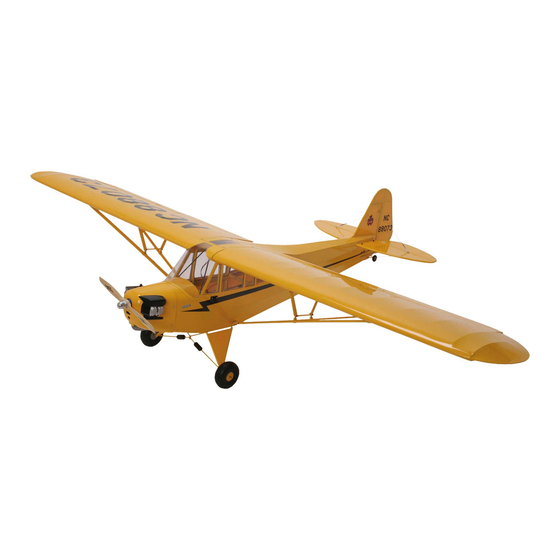
Introduction Thank you for your purchase of the Hangar 9 1/4 Scale Piper J-3 Cub. This kit will provide you with a scale model of the original Piper J-3 Cub. We believe the design is perfect for R/C and makes a beautiful model that will be easy to fly. -
Page 4: Additional Required Equipment
Additional Required Equipment Radio Equipment 4 Channel minumum 5 Servos (JRPS531 or equivalent) Standard 600-1100mAh receiver battery pack "Y" Harness or servo extension Recommended JR Systems JR 400EX JR 421 EX JR XP652 JR XP783/388 JR XP8103 JR 10X JR PCM10SX Engine Requirements 1.08 - 1.48 2-cycle engines 1.20 - 1.80 4-cycle engines... - Page 5 Parts Needed (not included in the kit) Aileron extension (2) (JRPA101, 18”, Gold) Y harness (1)(JRPA133) (Needed to connect aileron servos to one channel (Aileron) of the receiver) Propeller (Refer to propeller recommendations listed in your engine’s operating instructions) Foam for cushioning tank Fuel tubing (12")(Gas or glow, depending on your choice of engine) Fuel filler Shut-off switch for gasoline engine operation (ZEN20000)
-
Page 6: Kit Contents
Kit Contents Note: Photo of product may vary slightly from contents in the box. Large Parts Left wing panel with aileron (HAN1551) Wing struts (HAN1556) Right wing panel with aileron (HAN1551) Fiberglass painted cowl (HAN1554) Fuselage (HAN1553) Horizontal stabilizer and elevator (HAN1552) Vertical stabilizer (fin) and rudder (HAN1552) Small Parts Windshield/Sidewindows (HAN1555) -
Page 7: Section 1. Assembling The Wing
Section 1: Assembling the Wing Parts Needed Tools and Adhesives Needed • Right wing panel with aileron and hinges • Instant thin CA glue • Left wing panel with aileron and hinges • CA remover/debonder • Paper towels • T-pins (one for each hinge) Note: The control surfaces, which include the ailerons, ele- Step 4. - Page 8 Section 1: Assembling the Wing CONTINUED Step 6. Deflect the aileron and completely saturate each hinge Step 9. Flex the aileron back and forth to “work in” the hinges with thin CA glue. The aileron’s front surface should lightly con- and check for proper movement.
-
Page 9: Section 2. Installing The Aileron Servos
Section 2: Installing the Aileron Servos Parts Needed Tools and Adhesives Needed • Right/left wing panels • Hobby knife with #11 blade • 6-minute epoxy • Standard size servos with mounting hardware (2) • Medium Phillips screwdriver • Rubbing alcohol Note: JRS 531 servos (or equivalent) are recommended. - Page 10 Section 2: Installing the Aileron Servos CONTINUED Step 4. Once you’re satisfied with the fit of the aileron servo in Step 6. Once the epoxy has cured, you can begin to mount the the aileron servo bay, proceed to epoxy the wood servo mounts servo into the wing.
- Page 11 Section 2: Installing the Aileron Servos CONTINUED Step 8. Trial fit the servo into the aileron servo bay. You will Step10. Using a 1/16" drill bit, drill the servo screw locations have to make sure the servo lead wire is not crimped. Note the previously marked in Step 4.
-
Page 12: Section 3. Installing The Aileron Linkages
Section 3: Installing the Aileron Linkages Parts Needed Tools and Adhesives Needed • Wing panels (right and left) • Medium Phillips screwdriver • Short (3-3/4") threaded rod (both ends) (2) • Drill • Clevis (4) • Drill bit: 1/16" • 4/40 nuts (4) •... - Page 13 Section 3: Installing the Aileron Linkages CONTINUED Step 5. Once you're satisfied with the control horn location Step 6. Using a 1/16" drill bit, drill the screw holes for mount- (remember, it should be a straight line from the servo arm to the ing the control horn.
-
Page 14: Section 4. Bolting The Wing To The Fuselage
Section 4: Bolting the Wing to the Fuselage Parts Needed Tools and Adhesives Needed • Left and right wing panels • Allen wrench (provided in kit) • Fuselage • Medium Phillips screwdriver • Aluminum wing brace 24 " long • Threadlock •... -
Page 15: Section 5. Installing The Horizontal And Vertical Stabilizers
Section 5: Installing the Horizontal and Vertical Stabilizer Parts Needed Tools and Adhesives Needed • Fuselage w/wing temporially mounted • Hobby knife with #11 blade • Ruler • Horizontal stabilizer • Felt-tipped pen • Pencil • Vertical stabilizer • 30-minute epoxy •... - Page 16 Section 5: Installing the Horizontal and Vertical Stabilizer CONTINUED Step 5. With the fuselage resting on a flat surface, align the Step 7. When you’re satisfied with the alignment of the horizon- horizontal stabilizer by measuring from fixed points on the wing tal stabilizer with the wing, carefully mark the position with a to the outside of the trailing edge tip of the horizontal stabilizer.
- Page 17 Section 5: Installing the Horizontal and Vertical Stabilizer CONTINUED Step 9. Carefully check the vertical stabilizer to make sure it’s Step 11. When you’re satisfied with the alignment, carefully aligned 90 degrees to the horizontal stabilizer. A 90-degree mark the position of the vertical stabilizer to fuselage with a pen- triangle is helpful in this step.
- Page 18 Section 5: Installing the Horizontal and Vertical Stabilizer CONTINUED Step 13. Mix up approximately 1/2 ounce (minimum) of Step 15. Mix up 1/2 ounce of 30-minute epoxy and apply to 30-minute epoxy to attach the horizontal stabilizer to the fuse- the vertical stabilizer where the fuselage contacts it.
-
Page 19: Section 6. Installing The Rudder And Elevator Control Horns
Section 6: Installing the Elevator and Rudder Control Horns Parts Needed Tools and Adhesives Needed • Control horns (3) • Thin CA glue • Control horn back plates (3) • CA debonder • Control horn screws (12) • Drill • Fuselage with horizontal and vertical stabilizers attached •... - Page 20 Section 6: Installing the Elevator and Rudder Control Horns CONTINUED Step 5. Using a 1/16" drill bit, drill two pilot holes for the horn. Step 9. Trial fit the rudder control horn centered on your mark After the holes are drilled, you will want to put a drop of CA glue and make sure the portion of the horn with the holes is centered in each hole to help strengthen the balsa.
Need help?
Do you have a question about the J-3 Piper Cub and is the answer not in the manual?
Questions and answers