
Related Manuals for IEI Technology KINO-KBN-i2


Summary of Contents for IEI Technology KINO-KBN-i2
-
Page 1: User Manual
KINO-KBN-i2 CPU Card MODEL: KINO-KBN-i2 Mini-ITX SBC with AMD® G-Series SoC Processor, DDR3, VGA/HDMI, Dual GbE, USB 3.0, Dual Mini PCIe, SATA 6Gb/s, Audio and RoHS User Manual Page I Rev. 1.02 - December 3, 2015... - Page 2 KINO-KBN-i2 Revision Date Version Changes December 3, 2015 1.02 Added a note regarding how to use USB 3.0 ports for Windows 7 OS installation in Section 3.3.2. March 12, 2014 1.01 Added chassis intrusion connector (CHASSIS1) Added IPMI LED connector (ID_BT_FP1) November 20, 2013 1.00...
- Page 3 KINO-KBN-i2 Copyright COPYRIGHT NOTICE The information in this document is subject to change without prior notice in order to improve reliability, design and function and does not represent a commitment on the part of the manufacturer. In no event will the manufacturer be liable for direct, indirect, special, incidental, or consequential damages arising out of the use or inability to use the product or documentation, even if advised of the possibility of such damages.
- Page 4 KINO-KBN-i2 Manual Conventions WARNING Warnings appear where overlooked details may cause damage to the equipment or result in personal injury. Warnings should be taken seriously. CAUTION Cautionary messages should be heeded to help reduce the chance of losing data or damaging the product.
-
Page 5: Table Of Contents
PTIONAL TEMS 3 CONNECTORS ......................13 3.1 P ..............14 ERIPHERAL NTERFACE ONNECTORS 3.1.1 KINO-KBN-i2 Layout ..................14 3.1.2 Peripheral Interface Connectors ..............15 3.1.3 External Interface Panel Connectors............... 16 3.2 I ..............17 NTERNAL ERIPHERAL ONNECTORS 3.2.1 AT/ATX Mode Select Switch................17 3.2.2 Battery Connector.................... - Page 6 KINO-KBN-i2 3.2.11 IPMI LED Connector ..................26 3.2.12 IPMI Slot......................27 3.2.13 Keyboard/Mouse Connector ................30 3.2.14 LAN LED Connector..................31 3.2.15 PCIe x4 Slot ....................32 3.2.16 PCIe Mini Card Slot ..................34 3.2.17 RS-232 Serial Port Connector ............... 37 3.2.18 RS-422/485 Serial Port Connector ..............
- Page 7 KINO-KBN-i2 4.4.2 Using the IEI iMAN Web GUI................61 5 BIOS ..........................64 5.1 I ......................65 NTRODUCTION 5.1.1 Starting Setup....................65 5.1.2 Using Setup ...................... 65 5.1.3 Getting Help..................... 66 5.1.4 Unable to Reboot after Configuration Changes ..........66 5.1.5 BIOS Menu Bar....................
- Page 8 KINO-KBN-i2 D.1 I ...................... 106 NTRODUCTION D.2 A 1................107 SSEMBLY ANGUAGE AMPLE D.3 A 2................107 SSEMBLY ANGUAGE AMPLE E WATCHDOG TIMER....................108 F HAZARDOUS MATERIALS DISCLOSURE............111 F.1 H IPB P AZARDOUS ATERIAL ISCLOSURE ABLE FOR RODUCTS ERTIFIED AS 2002/95/EC W ..........112...
- Page 9 KINO-KBN-i2 List of Figures Figure 1-1: KINO-KBN-i2 ........................2 Figure 1-2: Connectors ........................4 Figure 1-3: Dimensions (mm) ......................5 Figure 1-4: Data Flow Diagram......................6 Figure 3-1: Connector and Jumper Locations................14 Figure 3-2: AT/ATX Mode Select Switch Location ..............17 Figure 3-3: Battery Connector Location..................18 Figure 3-4: Chassis Intrusion Connector Location..............19...
- Page 10 KINO-KBN-i2 Figure 3-28: USB Connector Locations..................47 Figure 3-29: External Peripheral Interface Connector ..............48 Figure 3-30: Audio Connector .....................48 Figure 3-31: LAN Connector......................49 Figure 3-32: Serial Port Pinout Locations ..................53 Figure 3-33: VGA Connector .......................53 Figure 4-1: SO-DIMM Installation ....................57 Figure 4-2: IPMI Module Installation ...................58 Figure 4-2: SATA Drive Cable Connection.................59...
- Page 11 KINO-KBN-i2 List of Tables Table 1-1: KINO-KBN-i2 Model Variations..................2 Table 1-2: Technical Specifications....................8 Table 3-1: Peripheral Interface Connectors ................16 Table 3-2: Rear Panel Connectors ....................16 Table 3-3: AT/ATX Mode Select Switch Settings...............17 Table 3-4: Battery Connector Pinouts ..................18 Table 3-5: Chassis Intrusion Connector Pinouts ..............19 Table 3-6: Clear CMOS Button Settings ..................20...
- Page 12 KINO-KBN-i2 Table 3-30: LAN2_USB2 Connector Pinouts ................50 Table 3-31: HDMI Connector Pinouts ..................52 Table 3-32: Power Connector Pinouts..................52 Table 3-33: Serial Port Pinouts....................53 Table 3-34: VGA Connector Pinouts...................53 Table 5-1: BIOS Navigation Keys ....................66 Page XII...
- Page 13 KINO-KBN-i2 List of BIOS Menus BIOS Menu 1: Main ........................67 BIOS Menu 2: Advanced ......................68 BIOS Menu 3: ACPI Configuration ....................69 BIOS Menu 4: RTC Wake Settings ....................70 BIOS Menu 5: Trusted Computing ....................71 BIOS Menu 6: CPU Configuration ....................72 BIOS Menu 7: IDE Configuration....................73...
-
Page 15: Introduction
KINO-KBN-i2 Chapter Introduction Page 1... -
Page 16: Introduction
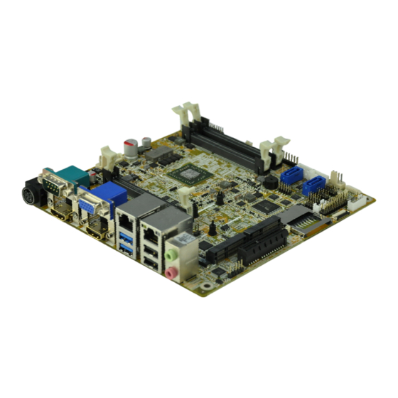
1.1 Introduction Figure 1-1: KINO-KBN-i2 The KINO-KBN-i2 Mini-ITX motherboard is an AMD® G-Series SoC processor platform. It supports two 1600/1333 MHz DDR3 SO-DIMM modules up to 8.0 GB. The KINO-KBN-i2 includes a VGA connector and two HDMI connectors. Expansion and I/O include two USB 3.0 connectors on the rear panel, two USB 2.0 connectors on the rear... -
Page 17: Features
KINO-KBN-i2 1.3 Features Some of the KINO-KBN-i2 motherboard features are listed below: Mini-ITX form factor with AMD® G-Series SoC processor supports DDR3 1600/1333 MHz memory 12V only single voltage design for AT/ATX power Dual independent display by VGA and dual HDMI ... -
Page 18: Connectors
KINO-KBN-i2 1.4 Connectors The connectors on the KINO-KBN-i2 are shown in the figure below. Figure 1-2: Connectors Page 4... -
Page 19: Dimensions
KINO-KBN-i2 1.5 Dimensions The dimensions of the board are listed below: Figure 1-3: Dimensions (mm) Page 5... -
Page 20: Data Flow
KINO-KBN-i2 1.6 Data Flow Figure 1-4 shows the data flow between the system chipset, the CPU and other components installed on the motherboard. Figure 1-4: Data Flow Diagram Page 6... -
Page 21: Technical Specifications
KINO-KBN-i2 1.7 Technical Specifications KINO-KBN-i2 technical specifications are listed below. Specification KINO-KBN-i2 AMD® G-Series SoC processor Memory Two 204-pin 1600/1333 MHz single-channel DDR3 SO-DIMM supported (system max. 8 GB) UEFI BIOS BIOS Ethernet LAN1 (LAN1_USB2): Intel® I210-AT PCIe controller with NCSI support LAN2 (LAN2_USB2): Intel®... -
Page 22: Table 1-2: Technical Specifications
KINO-KBN-i2 Specification KINO-KBN-i2 1 x KB/MS (6-pin wafer) Keyboard/Mouse 1 x SD card SD Card 1 x Front panel (power LED, HDD LED, speaker, power button, reset Front Panel button) LAN LED 2 x LAN LED connector (2-pin, 1x2) SMBus... -
Page 23: Unpacking
KINO-KBN-i2 Chapter Unpacking Page 9... -
Page 24: Anti-Static Precautions
Only handle the edges of the PCB: Don't touch the surface of the motherboard. Hold the motherboard by the edges when handling. 2.2 Unpacking Precautions When the KINO-KBN-i2 is unpacked, please do the following: Follow the antistatic guidelines above. -
Page 25: Packing List
If any of the components listed in the checklist below are missing, do not proceed with the installation. Contact the IEI reseller or vendor the KINO-KBN-i2 was purchased from or contact an IEI sales representative directly by sending an email to sales@ieiworld.com. -
Page 26: Optional Items
KINO-KBN-i2 2.4 Optional Items The following are optional components which may be separately purchased: Item and Part Number Image IPMI 2.0 adapter card with AST2400 BMC chip (P/N: iRIS-2400-R10) Dual-port USB cable with bracket (P/N: CB-USB02A-RS) RS-422/485 cable, 200mm (P/N: 32205-003800-300-RS) -
Page 27: Connectors
KINO-KBN-i2 Chapter Connectors Page 13... -
Page 28: Peripheral Interface Connectors
KINO-KBN-i2 3.1 Peripheral Interface Connectors This chapter details all the jumpers and connectors. 3.1.1 KINO-KBN-i2 Layout The figures below show all the connectors and jumpers. Figure 3-1: Connector and Jumper Locations Page 14... -
Page 29: Peripheral Interface Connectors
KINO-KBN-i2 3.1.2 Peripheral Interface Connectors The table below lists all the connectors on the board. Connector Type Label AT/ATX mode select switch switch J_ATX_AT1 Battery connector 2-pin wafer BAT1 Chassis intrusion connector 2-pin header CHASSIS1 Clear CMOS button button J_CMOS1... -
Page 30: External Interface Panel Connectors
KINO-KBN-i2 SATA_PWR2 SD card slot SD card slot SMBus connectors 4-pin wafer CN1, CN2 S/PDIF connector 5-pin header SPDIF1 SPI Flash connectors 6-pin wafer SPI1, SPI2 System fan connector 4-pin wafer FAN2 TPM connector 20-pin connector TPM1 USB connector 8-pin header... -
Page 31: Internal Peripheral Connectors
KINO-KBN-i2 3.2 Internal Peripheral Connectors The section describes all of the connectors on the KINO-KBN-i2. 3.2.1 AT/ATX Mode Select Switch CN Label: J_ATX_AT1 CN Type: switch CN Location: See Figure 3-2 CN Settings: See Table 3-3 The AT/ATX mode select switch specifies the systems power mode as AT or ATX. -
Page 32: Battery Connector
KINO-KBN-i2 3.2.2 Battery Connector CN Label: BAT1 CN Type: 2-pin wafer CN Location: See Figure 3-3 CN Pinouts: See Table 3-4 The battery connector is connected to the system battery. The battery provides power to the system clock to retain the time when power is turned off. -
Page 33: Chassis Intrusion Connector
KINO-KBN-i2 3.2.3 Chassis Intrusion Connector CN Label: CHASSIS1 2-pin header CN Type: CN Location: F igure 3-4 CN Pinouts: See Table 3-5 The chassis intrusion connector is for a chassis intrusion detection sensor or switch that detects if a chassis component is removed or replaced. -
Page 34: Cpu Fan Connector
KINO-KBN-i2 If the KINO-KBN-i2 fails to boot due to improper BIOS settings, use the button to clear the CMOS data and reset the system BIOS information. The clear CMOS button settings are shown in Table 3-6. Setting Description Open Normal Operation... -
Page 35: Cpu Power Connector
KINO-KBN-i2 Figure 3-6: CPU Fan Connector Locations PIN NO. DESCRIPTION PIN NO. DESCRIPTION +12V FAN1IN FAN1OUT Table 3-7: CPU Fan Connector Pinouts 3.2.6 CPU Power Connector CN Label: PWR1 CN Type: 4-pin Molex CN Location: See Figure 3-7 CN Pinouts: See Table 3-8 The CPU power connector provides power to the CPU. -
Page 36: Ddr3 So-Dimm Slots
KINO-KBN-i2 Figure 3-7: CPU Power Connector Location PIN NO. DESCRIPTION PIN NO. DESCRIPTION GND_VIN GND_VIN 12VIN_1 12VIN_1 Table 3-8: CPU Power Connector Pinouts 3.2.7 DDR3 SO-DIMM Slots CN Label: DIMM1, DIMM2 CN Type: DDR3 SO-DIMM slot CN Location: See Figure 3-8 The DDR3 SO-DIMM slot is for DDR3 SO-DIMM memory module. -
Page 37: Digital I/O Connector
KINO-KBN-i2 Figure 3-8: DDR3 SO-DIMM Slot Location 3.2.8 Digital I/O Connector CN Label: DIO1 CN Type: 10-pin header CN Location: See Figure 3-9 CN Pinouts: See Table 3-9 The digital I/O connector provides programmable input and output for external devices. -
Page 38: Ec Debug Connector
KINO-KBN-i2 Figure 3-9: Digital I/O Connector Location PIN NO. DESCRIPTION PIN NO. DESCRIPTION DOUT3 DOUT2 DOUT1 DOUT0 DIN3 DIN2 DIN1 DIN0 Table 3-9: Digital I/O Connector Pinouts 3.2.9 EC Debug Connector CN Label: LPT_DB1 20-pin FPC connector CN Type: CN Location:... -
Page 39: Front Panel Connector
KINO-KBN-i2 Figure 3-10: EC Debug Connector Location Description Description KSI0 KSO9 KSO0 KSO10 KSO1 KSO12 KSO2 KSI1 KSO3 KSO11 KSO4 KSI2 KSO5 KSI3 KSO6 KSO7 KSO8 Table 3-10: EC Debug Connector Pinouts 3.2.10 Front Panel Connector CN Label: F_PANEL1 10-pin header... -
Page 40: Ipmi Led Connector
KINO-KBN-i2 Figure 3-11: Front Panel Connector Location PIN NO. DESCRIPTION PIN NO. DESCRIPTION PWRBTN+ HDD LED+ HDD LED- PWR LED+ PWR LED+ PWR LED- RST BTN+ Table 3-11: Front Panel Connector Pinouts 3.2.11 IPMI LED Connector CN Label: ID_BT_FP1 2-pin header... -
Page 41: Ipmi Slot
KINO-KBN-i2 Figure 3-12: IPMI LED Connector Location Description +V3.3A_EC_PLL ID_BT_FP# Table 3-12: IPMI LED Connector Pinouts 3.2.12 IPMI Slot CN Label: IPMI1 CN Type: IPMI slot CN Location: See Figure 3-13 CN Pinouts: See Table 3-13 The IPMI slot is for IPMI module card. -
Page 42: Figure 3-13: Ipmi Slot Location
KINO-KBN-i2 Figure 3-13: IPMI Slot Location DESCRIPTION DESCRIPTION DESCRIPTION DESCRIPTION VGA_G2 NC_SI_RXD1 PMBUS_ALERT# SDATA1_LAN1 NC_SI_TXD1 VGA_R2 +5V_DUAL +5V_DUAL VGA_B2 DATA5_P DATA4_P NC_SI_CRS_DV DATA5_N NC_SI_CLK_IN DATA4_N NC_SI_TX_EN VSYNC2 +5V_DUAL +5V_DUAL RTS#4 HSYNC2 APU_PROCHOT# APU_VDD_RUN RXD4 _IPMI DTR#4 VI_DDCDAT +3.3V +0.95V_ALW TXD4... - Page 43 KINO-KBN-i2 SPI_SWITCH SMB_PCIE_3V3 +3.3V BMC_TXD5 _CLK SMB_IPMB_3VS APU_VDD_RUN +3.3V DSR#4 B_CLK SMB_PCIE_3V3 ID_BT_FP# BMC_RXD5 _DATA SMB_IPMB_3VS +3.3V_DUAL CTS#4 B_DATA +3.3V_DUAL IPMI_DET# BMC_SPKR AMBER_LED-_B SPI_BMC_BIOS_CS LAD2 SPI_PATBRG_R_CS LAD0 APU_VDD_PWR GREEN_LED-_B SPI_BMC_BIOS_CL LAD3 GD_IPMI +3.3V_DUAL SPI_PATBRG_R_CL LAD1 +3.3V_DUAL SMB_TEMP_3VS ID_LED#_BMC SMI_ACTIVE# PWRBTSW#...
-
Page 44: Keyboard/Mouse Connector
KINO-KBN-i2 SDATA1_BMC GPP_CLK3P SPI_BMC_BIOS_MI SERIRQ SDATA1_LAN2 +3.3V_DUAL +3.3V_DUAL IPMI_RXN PM_RSMRST#_ SYS_PWRGD_IP IPMI_TXN PME# IPMI_RXP SYS_PWRGD_IP IPMI_TXP SLP_S3# +5V_DUAL SLP_S4# +5V_DUAL SLP_S5# NC_SI_RXD0 PBG_SYS_RESET_N BMC_PSON _BMC ACLK_LAN1 NC_SI_TXD0 PS_ON# Table 3-13: IPMI Slot Pinouts 3.2.13 Keyboard/Mouse Connector CN Label: KB_MS1 CN Type:... -
Page 45: Lan Led Connector
KINO-KBN-i2 Figure 3-14: Keyboard/Mouse Connector Location Description VCC5_KBMS MSDATA MSCLK KBDATA KBCLK KBMS_GND Table 3-14: Keyboard/Mouse Connector Pinouts 3.2.14 LAN LED Connector CN Label: LED_LAN2, LED_LAN3 2-pin header CN Type: CN Location: See Figure 3-15 CN Pinouts: See Table 3-15 The LAN LED connectors connect to the LAN link LEDs on the system. -
Page 46: Pcie X4 Slot
KINO-KBN-i2 Figure 3-15: LAN LED Connector Location PIN NO. DESCRIPTION PIN NO. DESCRIPTION L1/2_LINK_ACT- Table 3-15: LAN LED Connector Pinouts 3.2.15 PCIe x4 Slot CN Label: PCIEX4 PCIe x4 slot CN Type: CN Location: See Figure 3-16 CN Pinouts: See Table 3-16 The PCIe x4 slot is for PCIe x4 expansion cards. -
Page 47: Figure 3-16: Pcie X4 Slot Location
KINO-KBN-i2 Figure 3-16: PCIe x4 Slot Location PIN NO. DESCRIPTION PIN NO. DESCRIPTION +12V +12V +12V +12V +12V SCLK1 SDATA1 +3.3V +3.3V +3.3V +3.3V_DUAL PCIE_RST# PCIE_WAKE_UP# GFX_CLK0P GFX_CLK0N P_GFX_TXP0 P_GFX_TXN0 P_GFX_RXP0 P_GFX_RXN0 P_GFX_TXP1 P_GFX_TXN1 Page 33... -
Page 48: Pcie Mini Card Slot
KINO-KBN-i2 P_GFX_RXP1 P_GFX_RXN1 P_GFX_TXP2 P_GFX_TXN2 P_GFX_RXP2 P_GFX_RXN2 P_GFX_TXP3 P_GFX_TXN3 P_GFX_RXP3 P_GFX_RXN3 Table 3-16: PCIe x4 Slot Pinouts 3.2.16 PCIe Mini Card Slot CN Label: M_PCIE1, M_PCIE2 CN Type: full-size PCIe mini card slot, half-size PCIe mini card slot CN Location:... -
Page 49: Figure 3-17: Pcie Mini Card Slot Location
KINO-KBN-i2 Figure 3-17: PCIe Mini Card Slot Location PIN NO. DESCRIPTION PIN NO. DESCRIPTION VCC3_MINI_1 +V1.5_MINI_1 SCLK1 MPCIE_TXDN +V1.5_MINI_1 SDATA1 MPCIE_TXDP USB6N GPP_CLK2N USB6P GPP_CLK2P VCC3_MINI_1 VCC3_MINI_1 PCIE_RST# N48174558 Page 35... -
Page 50: Table 3-17: Pcie Mini Card Slot Pinouts (M_Pcie1)
KINO-KBN-i2 PIN NO. DESCRIPTION PIN NO. DESCRIPTION PCIE_RST# +V1.5_MINI_1 MPCIE_RXDN +3.3V_DUAL MPCIE_RXDP mSATA_DET# VCC3_MINI_1 Table 3-17: PCIe Mini Card Slot Pinouts (M_PCIE1) PIN NO. DESCRIPTION PIN NO. DESCRIPTION VCC3_MINI_2 +V1.5_MINI_2 SCLK1 MINISLOT1_TXDN +V1.5_MINI_2 SDATA1 MINI_PCIE_SLT1_CLKREQ# MINISLOT1_TXDP USB7N USB7P VCC3_MINI_2 VCC3_MINI_2... -
Page 51: Serial Port Connector
KINO-KBN-i2 PIN NO. DESCRIPTION PIN NO. DESCRIPTION MINISLOT1_RXDN +3.3V_DUAL MINISLOT1_RXDP VCC3_MINI_2 Table 3-18: PCIe Mini Card Slot Pinouts (M_PCIE2) 3.2.17 RS-232 Serial Port Connector CN Label: COM2, COM3, COM5 CN Type: 10-pin header CN Location: See Figure 3-18 CN Pinouts: See Table 3-19 The serial connector provides RS-232 connection. -
Page 52: Rs-422/485 Serial Port Connector
KINO-KBN-i2 PIN NO. DESCRIPTION PIN NO. DESCRIPTION NDTR2/3/5 NRI2/3/5 Table 3-19: RS-232 Serial Port Connector Pinouts 3.2.18 RS-422/485 Serial Port Connector CN Label: COM6 CN Type: 4-pin wafer CN Location: See Figure 3-19 CN Pinouts: See Table 3-20 This connector provides RS-422 or RS-485 communications. -
Page 53: Sata 6Gb/S Drive Connector
KINO-KBN-i2 3.2.19 SATA 6Gb/s Drive Connector CN Label: SATA1, SATA2 CN Type: 7-pin SATA connector CN Location: See Figure 3-20 The SATA 6Gb/s drive connector is connected to a SATA 6Gb/s drive. The SATA 6Gb/s drive transfers data at speeds as high as 6Gb/s. -
Page 54: Sd Card Slot
+12V Table 3-21: SATA Power Connector Pinouts 3.2.21 SD Card Slot CN Label: CN Type: SD card slot See Figure 3-22 CN Location: An SD memory card can be inserted to the SD card slot on the KINO-KBN-i2. Page 40... -
Page 55: Smbus Connector
KINO-KBN-i2 Figure 3-22: SD Card Slot Location 3.2.22 SMBUS Connector CN Label: CN1, CN2 CN Type: 4-pin wafer CN Location: See Figure 3-23 CN Pinouts: See Table 3-22 The SMBus (System Management Bus) connector provides low-speed system management communications. Page 41... -
Page 56: S/Pdif Connector
KINO-KBN-i2 Figure 3-23: SMBus Connector Location PIN NO. DESCRIPTION PIN NO. DESCRIPTION SDATA0/1 SCLK0/1 Table 3-22: SMBus Connector Pinouts 3.2.23 S/PDIF Connector CN Label: SPDIF1 CN Type: 5-pin header CN Location: See Figure 3-24 CN Pinouts: See Table 3-23 Use the S/PDIF connector to connect digital audio devices to the system. -
Page 57: Spi Flash Connector
KINO-KBN-i2 Figure 3-24: S/PDIF Connector Location Description SPDIF OUT SPDIF IN Table 3-23: S/PDIF Connector Pinouts 3.2.24 SPI Flash Connector CN Label: SPI1, SPI2 6-pin wafer CN Type: CN Location: See Figure 3-25 CN Pinouts: See Table 3-24 and Table 3-25 The SPI Flash connector is used to flash the BIOS. -
Page 58: System Fan Connector
KINO-KBN-i2 Figure 3-25: SPI Flash Connector Location PIN NO. DESCRIPTION PIN NO. DESCRIPTION SPI_POWER SPI_CS#_CONN SPI_DATAIN_CONN SPI_CLK_CONN SPI_DATAOUT_CONN Table 3-24: SPI Flash Connector Pinouts (SPI1) PIN NO. DESCRIPTION PIN NO. DESCRIPTION EC_SPI_VCC FSCE# FMISO FSCK FMOSI Table 3-25: SPI Flash Connector Pinouts (SPI2) 3.2.25 System Fan Connector... -
Page 59: Tpm Connector
KINO-KBN-i2 Figure 3-26: System Fan Connector Locations PIN NO. DESCRIPTION PIN NO. DESCRIPTION +12V FAN2IN FAN2OUT Table 3-26: System Fan Connector Pinouts 3.2.26 TPM Connector CN Label: TPM1 CN Type: 20-pin connector CN Location: See Figure 3-27 CN Pinouts: See Table 3-27 The Trusted Platform Module (TPM) connector secures the system on bootup. -
Page 60: Usb Connector
KINO-KBN-i2 Figure 3-27: TPM Connector Location PIN NO. DESCRIPTION PIN NO. DESCRIPTION LPC_CLK1 LFRAME# LPC_RST# LAD3 LAD2 +3.3V LAD1 LAD0 SCLK0 SDATA0 SERIRQ +3.3V_DUAL LPC_CLKRUN# LPCPD# LDRQ#0 Table 3-27: TPM Connector Pinouts 3.2.27 USB Connector CN Label: USB3 CN Type:... -
Page 61: Figure 3-28: Usb Connector Locations
KINO-KBN-i2 The USB connector provides two USB 2.0 ports by dual-port USB cable. Figure 3-28: USB Connector Locations PIN NO. DESCRIPTION PIN NO. DESCRIPTION USBV2L DATA2_N DATA3_P DATA2_P DATA3_N USBV2L Table 3-28: USB Connector Pinouts Page 47... -
Page 62: External Peripheral Interface Connector Panel
KINO-KBN-i2 3.3 External Peripheral Interface Connector Panel Figure 3-29 shows the KINO-KBN-i2 external peripheral interface connector (EPIC) panel. The EPIC panel consists of the following: Figure 3-29: External Peripheral Interface Connector 3.3.1 Audio Connector CN Label: AUDIO_CV2 CN Type: Audio jacks... -
Page 63: Ethernet And Usb Connectors
KINO-KBN-i2 3.3.2 Ethernet and USB Connectors CN Label: LAN1_USB2, LAN2_USB2 CN Type: RJ-45 , USB 2.0 and USB 3.0 ports CN Location: See Figure 3-29 CN Pinouts: See Figure 3-31 , Table 3-29 and Table 3-30 The LAN connector connects to a local network. LAN1 supports IPMI 2.0 through the optional iRIS-2400 module. -
Page 64: Table 3-29: Lan1_Usb2 Connector Pinouts
KINO-KBN-i2 L1_1000- L1_LINK_ACT- +V3.3LAN1 Table 3-29: LAN1_USB2 Connector Pinouts The USB 3.0 ports are for attaching USB 3.0 peripheral devices to the system. To be able to use the USB 3.0 ports, please make sure the USB 3.0 driver is installed. The pinouts of LAN2 and USB 3.0 connectors are shown below. -
Page 65: Hdmi Connector
KINO-KBN-i2 NOTE: During Windows 7 OS installation, the USB 3.0 functionality will be disabled until the USB 3.0 drivers are installed. In order to use USB 3.0 ports for OS installation, the following steps must be followed: 1. Copy the USB 3.0 drivers from the driver CD to a USB flash drive. -
Page 66: Power Connector
KINO-KBN-i2 Description Description HDMI_DATA0# HDMI_GND HDMI_CLK HDMI_GND HDMI_GND HDMI_CLK# Table 3-31: HDMI Connector Pinouts 3.3.4 Power Connector CN Label: PWR2 CN Type: 4-pin DIN CN Location: See Figure 3-29 CN Pinouts: See Table 3-32 The power connector supports 12V DC power input. -
Page 67: Vga Connector
KINO-KBN-i2 Description Description NTX1 NCTS1 NDTR1 NRI1 Table 3-33: Serial Port Pinouts Figure 3-32: Serial Port Pinout Locations 3.3.6 VGA Connector CN Label: VGA1 CN Type: D-sub 15-pin female connector CN Location: See Figure 3-29 CN Pinouts: See Figure 3-33 an Table 3-34 The standard 15-pin female VGA connector connects to a CRT or LCD monitor. -
Page 68: Installation
KINO-KBN-i2 Chapter Installation Page 54... -
Page 69: Anti-Static Precautions
Electrostatic discharge (ESD) can cause serious damage to electronic components, including the KINO-KBN-i2. Dry climates are especially susceptible to ESD. It is therefore critical that whenever the KINO-KBN-i2 or any other electrical component is handled, the following anti-static precautions are strictly adhered to. - Page 70 Turn all power to the KINO-KBN-i2 off: When working with the KINO-KBN-i2, make sure that it is disconnected from all power supplies and that no electricity is being fed into the system. Before and during the installation of the KINO-KBN-i2 DO NOT: ...
-
Page 71: So-Dimm Installation
KINO-KBN-i2 4.2.1 SO-DIMM Installation To install a SO-DIMM, please follow the steps below and refer to Figure 4-1. Figure 4-1: SO-DIMM Installation Step 1: Open the SO-DIMM socket handles. Open the two handles outwards as far as they can. See Figure 4-1. -
Page 72: Ipmi Module Installation (Optional)
The IPMI module slot is designed to install the IEI iRIS-2400 IPMI 2.0 module only. DO NOT install other modules into the IPMI module slot. Doing so may cause damage to the KINO-KBN-i2. To install the iRIS-2400 module, please follow the steps below and refer to Figure 4-2. -
Page 73: Internal Peripheral Device Connections
This section outlines the installation of peripheral devices to the on-board connectors 4.3.1 SATA Drive Connection The KINO-KBN-i2 is shipped with two SATA drive cable. To connect the SATA drive to the connector, please follow the steps below. Step 1: Locate the SATA connector and the SATA power connector. -
Page 74: Single Rs-232 Cable
KINO-KBN-i2 Step 4: To remove the SATA cable from the SATA connector, press the clip on the connector at the end of the cable. Step 0: 4.3.2 Single RS-232 Cable The single RS-232 cable consists of one serial port connector attached to a serial communications cable that is then attached to a D-sub 9 male connector. -
Page 75: Ipmi Setup Procedure
The KINO-KBN-i2 features Intelligent Platform Management Interface (IPMI) that helps lower the overall costs of server management by enabling users to maximize IT resources, save time and manage multiple systems. The KINO-KBN-i2 supports IPMI 2.0 through the optional iRIS-2400 module. Follow the steps below to setup IPMI. -
Page 76: Figure 4-5: Iei Iman Web Address
KINO-KBN-i2 Step 2: On the remote management console, open a web browser. Enter the managed system IP address in the web browser (Figure 4-5). Figure 4-5: IEI iMAN Web Address Step 3: The login page appears in the web browser. - Page 77 KINO-KBN-i2 NOTE: To understand how to use the IEI iMAN Web GUI, please refer to the iRIS-2400 Web GUI user manual in the utility CD came with the KINO-KBN-i2. The user manual describes each function in detail. Page 63...
-
Page 78: Bios
KINO-KBN-i2 Chapter BIOS Page 64... -
Page 79: Introduction
KINO-KBN-i2 5.1 Introduction The BIOS is programmed onto the BIOS chip. The BIOS setup program allows changes to certain system settings. This chapter outlines the options that can be changed. 5.1.1 Starting Setup The UEFI BIOS is activated when the computer is turned on. The setup program can be activated in one of two ways. -
Page 80: Getting Help
KINO-KBN-i2 Function Main Menu – Quit and do not save changes into CMOS Status Page Setup Menu and Option Page Setup Menu -- Exit current page and return to Main Menu General help, only for Status Page Setup Menu and Option... -
Page 81: Main
KINO-KBN-i2 5.2 Main The Main BIOS menu (BIOS Menu 1) appears when the BIOS Setup program is entered. The Main menu gives an overview of the basic system information. Aptio Setup Utility – Copyright (C) 2012 American Megatrends, Inc. Main... -
Page 82: Advanced
KINO-KBN-i2 System Time [xx:xx:xx] Use the System Time option to set the system time. Manually enter the hours, minutes and seconds. 5.3 Advanced Use the Advanced menu (BIOS Menu 2) to configure the CPU and peripheral devices through the following sub-menus:... -
Page 83: Rtc Wake Settings
KINO-KBN-i2 Aptio Setup Utility – Copyright (C) 2012 American Megatrends, Inc. Advanced ACPI Settings ACPI Sleep State [S3 only(Suspend to…] ---------------------- : Select Screen : Select Item Enter Select +/-: Change Opt. General Help Previous Values Optimized Defaults Save & Exit ESC: Exit Version 2.15.1236. -
Page 84: Bios Menu 4: Rtc Wake Settings
KINO-KBN-i2 Aptio Setup Utility – Copyright (C) 2012 American Megatrends, Inc. Advanced RTC Wake Settings Enable or disable System wake on alarm event. When Wake system with Fixed Time [Disabled] enabled, System will wake on the date::hr::min::sec specified ---------------------- : Select Screen ... -
Page 85: Trusted Computing
KINO-KBN-i2 5.3.3 Trusted Computing Use the Trusted Computing menu (BIOS Menu 5) to configure settings related to the Trusted Computing Group (TCG) Trusted Platform Module (TPM). Aptio Setup Utility – Copyright (C) 2012 American Megatrends, Inc. Advanced Configuration Enables or Disables BIOS... -
Page 86: Cpu Configuration
KINO-KBN-i2 5.3.4 CPU Configuration Use the CPU Configuration menu (BIOS Menu 6) to view detailed CPU specifications and configure the CPU. Aptio Setup Utility – Copyright (C) 2012 American Megatrends, Inc. Advanced CPU Configuration Enable/disable CPU Virtualization Socket0: AMD GX-210HA SOC with Radeon(tm)HD Graphics... -
Page 87: Ide Configuration
KINO-KBN-i2 Three cores per Active three of the processor cores processor Active two of the processor cores cores processor core Active one of the processor cores processor 5.3.5 IDE Configuration Use the IDE Configuration menu (BIOS Menu 7) to change and/or set the configuration of the SATA devices installed in the system. -
Page 88: Usb Configuration
KINO-KBN-i2 Configures SATA devices as normal IDE device. EFAULT Configures SATA devices as AHCI device. AHCI 5.3.6 USB Configuration Use the USB Configuration menu (BIOS Menu 8) to read USB configuration information and configure the USB settings. Aptio Setup Utility – Copyright (C) 2012 American Megatrends, Inc. -
Page 89: F81866 Super Io Configuration
KINO-KBN-i2 keyboard can control the system even when there is no USB driver loaded onto the system. Enabled Legacy USB support enabled EFAULT Disabled Legacy USB support disabled Auto Legacy USB support disabled if no USB devices are connected 5.3.7 F81866 Super IO Configuration... -
Page 90: Serial Port N Configuration
KINO-KBN-i2 5.3.7.1 Serial Port n Configuration Use the Serial Port n Configuration menu (BIOS Menu 10) to configure the serial port n. Aptio Setup Utility – Copyright (C) 2012 American Megatrends, Inc. Advanced Serial Port 1 Configuration Enable or Disable Serial... - Page 91 KINO-KBN-i2 IO=3F8h; IRQ=3, Serial Port I/O port address is 3F8h and the 4,5,6,7,10,11,12 interrupt address is IRQ3,4,5,6,7,10,11,12 Serial Port I/O port address is 2F8h and the IO=2F8h; IRQ=3, interrupt address is IRQ3,4,5,6,7,10,11,12 4,5,6,7,10,11,12 IO=3E8h; IRQ=3, Serial Port I/O port address is 3E8h and the...
- Page 92 KINO-KBN-i2 IO=2E8h; IRQ=3, Serial Port I/O port address is 2E8h and the 4,5,6,7,10,11,12 interrupt address is IRQ3,4,5,6,7,10,11,12 5.3.7.1.3 Serial Port 3 Configuration Serial Port [Enabled] Use the Serial Port option to enable or disable the serial port. ...
- Page 93 KINO-KBN-i2 5.3.7.1.4 Serial Port 5 Configuration Serial Port [Enabled] Use the Serial Port option to enable or disable the serial port. Disabled Disable the serial port Enable the serial port Enabled EFAULT Change Settings [Auto] Use the Change Settings option to change the serial port IO port address and interrupt address.
- Page 94 KINO-KBN-i2 Disabled Disable the serial port Enable the serial port Enabled EFAULT Change Settings [Auto] Use the Change Settings option to change the serial port IO port address and interrupt address. Auto The serial port IO port address and interrupt EFAULT address are automatically detected.
-
Page 95: F81866 H/W Monitor
KINO-KBN-i2 5.3.8 F81866 H/W Monitor The F8186 H/W Monitor menu (BIOS Menu 11) shows the operating temperature, fan speeds and system voltages. Aptio Setup Utility – Copyright (C) 2012 American Megatrends, Inc. Advanced PC Health Status Enable or Disable Smart... -
Page 96: Smart Fan Mode Configuration
KINO-KBN-i2 Disabled Disables the smart fan function. Enables the smart fan function. Enabled EFAULT 5.3.8.1 Smart Fan Mode Configuration Use the Smart Fan Mode Configuration submenu (BIOS Menu 12) to configure the smart fan temperature and speed settings. -
Page 97: Serial Port Console Redirection
KINO-KBN-i2 CPU Temperature n Use the + or – key to change the fan CPU Temperature n value. Enter a decimal number between 1 and 100. FAN2 Smart Fan Control [Auto Duty-Cycle Mode] Use the FAN2 Smart Fan Control option to configure the System Smart Fan. -
Page 98: Console Redirection Settings
KINO-KBN-i2 Aptio Setup Utility – Copyright (C) 2012 American Megatrends, Inc. Advanced COM1 Console Redirection Console Redirection [Disabled] Enable or Disable > Console Redirection Settings COM2 Console Redirection [Disabled] > Console Redirection Settings COM3 Console Redirection [Disabled] > Console Redirection Settings --------------------- : Select Screen... -
Page 99: Bios Menu 14: Console Redirection Settings
KINO-KBN-i2 Aptio Setup Utility – Copyright (C) 2012 American Megatrends, Inc. Advanced COM1 Emulation: ANSI: Console Redirection Settings Extended ASCII char set. VT100: ASCII char set. Terminal Type [ANSI] VT100+: Extends VT100 to Bits per second [115200] support color, function Data Bits keys, etc. - Page 100 KINO-KBN-i2 38400 Sets the serial port transmission speed at 38400. Sets the serial port transmission speed at 57600. 57600 115200 Sets the serial port transmission speed at 115200. EFAULT Data Bits [8] Use the Data Bits option to specify the number of data bits.
-
Page 101: Chipset
KINO-KBN-i2 5.4 Chipset Use the Chipset menu (BIOS Menu 15) to access the PCH-IO and System Agent (SA) configuration menus. WARNING! Setting the wrong values for the Chipset BIOS selections in the Chipset BIOS menu may cause the system to malfunction. -
Page 102: South Bridge Configuration
KINO-KBN-i2 Aptio Setup Utility – Copyright (C) 2012 American Megatrends, Inc. Advanced GFX Configuration Set UMA FB Size UMA Frame Buffer Size [256M] --------------------- : Select Screen : Select Item Enter Select +/-: Change Opt. General Help Previous Values... -
Page 103: Bios Menu 17: South Bridge Configuration
KINO-KBN-i2 Aptio Setup Utility – Copyright (C) 2012 American Megatrends, Inc. Chipset Auto Power Button Function [Enabled(AT)] HD Audio Azalia Device [Enabled] Azalia Front Panel [Auto] --------------------- : Select Screen : Select Item Power Saving Function(ERP) [Disabled] Enter Select +/-: Change Opt. -
Page 104: North Bridge Configuration
KINO-KBN-i2 Power Saving Function(ERP) [Disabled] Use the Power Saving Function BIOS option to enable or disable the power saving function. Disabled Power saving function is disabled. EFAULT Power saving function is enabled. It will reduce power Enabled consumption when the system is off. -
Page 105: Boot
KINO-KBN-i2 5.5 Boot Use the Boot menu (BIOS Menu 19) to configure system boot options. Aptio Setup Utility – Copyright (C) 2012 American Megatrends, Inc. Main Advanced Chipset Boot Security Save & Exit Boot Configuration Select the keyboard Bootup NumLock State... - Page 106 KINO-KBN-i2 Quiet Boot [Enabled] Use the Quiet Boot BIOS option to select the screen display when the system boots. Normal POST messages displayed Disabled Enabled OEM Logo displayed instead of POST messages EFAULT Launch PXE OpROM [Disabled] Use the Launch PXE OpROM option to enable or disable boot option for legacy network devices.
-
Page 107: Security
KINO-KBN-i2 Boot Option Priority Use the Boot Option Priority function to set the system boot sequence from the available devices. The drive sequence also depends on the boot sequence in the individual device section. 5.6 Security Use the Security menu (BIOS Menu 20) to set system and user passwords. -
Page 108: Bios Menu 21:Exit
KINO-KBN-i2 Aptio Setup Utility – Copyright (C) 2012 American Megatrends, Inc. Main Advanced Chipset Boot Security Save & Exit Save Changes and Reset Reset the system after Discard Changes and Reset saving the changes. Restore Defaults Save as User Defaults... -
Page 109: A Regulatory Compliance
KINO-KBN-i2 Appendix Regulatory Compliance Page 95... - Page 110 KINO-KBN-i2 DECLARATION OF CONFORMITY This equipment has been tested and found to comply with specifications for CE marking. If the user modifies and/or installs other devices in the equipment, the CE conformity declaration may no longer apply. FCC WARNING This equipment complies with Part 15 of the FCC Rules. Operation is subject to the following two conditions: ...
-
Page 111: B Bios Menu Options
KINO-KBN-i2 Appendix BIOS Menu Options Page 97... - Page 112 KINO-KBN-i2 BIOS Information .........................67 System Date [xx/xx/xx] ......................67 System Time [xx:xx:xx] .......................68 ACPI Sleep State [S3 only (Suspend to RAM)] ..............69 Wake system with Fixed Time [Disabled]................70 Security Device Support [Disable] ..................71 SVM Mode [Enabled] ......................72 ...
- Page 113 KINO-KBN-i2 UMA Frame Buffer Size [256M]...................88 HD Audio Azalia Device [Enabled] ..................89 Azalia Front Panel [Enabled] ....................89 Power Saving Function(ERP) [Disabled]................90 Bootup NumLock State [On]....................91 Quiet Boot [Enabled] ......................92 Launch PXE OpROM [Disabled] ..................92 ...
-
Page 114: C Terminology
KINO-KBN-i2 Appendix Terminology Page 100... - Page 115 KINO-KBN-i2 AC ’97 Audio Codec 97 (AC’97) refers to a codec standard developed by Intel® in 1997. ACPI Advanced Configuration and Power Interface (ACPI) is an OS-directed configuration, power management, and thermal management interface. AHCI Advanced Host Controller Interface (AHCI) is a SATA Host controller register-level interface.
- Page 116 KINO-KBN-i2 computer is usually a male DE-9 connector. The Digital-to-Analog Converter (DAC) converts digital signals to analog signals. Double Data Rate refers to a data bus transferring data on both the rising and falling edges of the clock signal. Direct Memory Access (DMA) enables some peripheral devices to bypass the system processor and communicate directly with the system memory.
- Page 117 KINO-KBN-i2 PCIe PCI Express (PCIe) is a communications bus that uses dual data lines for full-duplex (two-way) serial (point-to-point) communications between the SBC components and/or expansion cards and the SBC chipsets. Each line has a 2.5 Gbps data transmission rate and a 250 MBps sustained data transfer rate.
- Page 118 KINO-KBN-i2 USB 2.0 supports 480Mbps data transfer rates. The Video Graphics Array (VGA) is a graphics display system developed by IBM. Page 104...
-
Page 119: D Digital I/O Interface
KINO-KBN-i2 Appendix Digital I/O Interface Page 105... - Page 120 KINO-KBN-i2 D.1 Introduction The DIO connector on the KINO-KBN-i2 is interfaced to GPIO ports on the Super I/O chipset. The DIO has both 4-bit digital inputs and 4-bit digital outputs. The digital inputs and digital outputs are generally control signals that control the on/off circuit of external devices or TTL devices.
- Page 121 KINO-KBN-i2 D.2 Assembly Language Sample 1 AX, 6F08H ;setting the digital port as input AL low byte = value AH – 6FH Sub-function: AL – 9 :Set the digital port as OUTPUT :Digital I/O input value D.3 Assembly Language Sample 2 AX, 6F09H ;setting the digital port as output...
-
Page 122: Watchdog Timer
KINO-KBN-i2 Appendix Watchdog Timer Page 108... - Page 123 KINO-KBN-i2 NOTE: The following discussion applies to DOS environment. IEI support is contacted or the IEI website visited for specific drivers for more sophisticated operating systems, e.g., Windows and Linux. The Watchdog Timer is provided to ensure that standalone systems can always recover from catastrophic conditions that cause the CPU to crash.
- Page 124 KINO-KBN-i2 NOTE: When exiting a program it is necessary to disable the Watchdog Timer, otherwise the system resets. Example program: ; INITIAL TIMER PERIOD COUNTER W_LOOP: AX, 6F02H ;setting the time-out value BL, 30H ;time-out value is 48 seconds ; ADD THE APPLICATION PROGRAM HERE EXIT_AP, 1 ;is the application over?
- Page 125 KINO-KBN-i2 Appendix Hazardous Materials Disclosure Page 111...
- Page 126 KINO-KBN-i2 F.1 Hazardous Material Disclosure Table for IPB Products Certified as RoHS Compliant Under 2002/95/EC Without Mercury The details provided in this appendix are to ensure that the product is compliant with the Peoples Republic of China (China) RoHS standards. The table below acknowledges the presences of small quantities of certain materials in the product, and is applicable to China RoHS only.
- Page 127 KINO-KBN-i2 Part Name Toxic or Hazardous Substances and Elements Lead Mercury Cadmium Hexavalent Polybrominated Polybrominated (Pb) (Hg) (Cd) Chromium Biphenyls Diphenyl Ethers (CR(VI)) (PBB) (PBDE) Housing Display Printed Circuit Board Metal Fasteners Cable Assembly Fan Assembly Power Supply Assemblies Battery...
- Page 128 KINO-KBN-i2 此附件旨在确保本产品符合中国 RoHS 标准。以下表格标示此产品中某有毒物质的含量符 合中国 RoHS 标准规定的限量要求。 本产品上会附有”环境友好使用期限”的标签,此期限是估算这些物质”不会有泄漏或突变”的 年限。本产品可能包含有较短的环境友好使用期限的可替换元件,像是电池或灯管,这些元 件将会单独标示出来。 部件名称 有毒有害物质或元素 铅 汞 镉 六价铬 多溴联苯 多溴二苯醚 (Pb) (Hg) (Cd) (CR(VI)) (PBB) (PBDE) 壳体 显示 印刷电路板 金属螺帽 电缆组装 风扇组装 电力供应组装 电池 O: 表示该有毒有害物质在该部件所有物质材料中的含量均在 SJ/T11363-2006 标准规定的限量要求以下。 X: 表示该有毒有害物质至少在该部件的某一均质材料中的含量超出 SJ/T11363-2006 标准规定的限量要求。...
Need help?
Do you have a question about the KINO-KBN-i2 and is the answer not in the manual?
Questions and answers