Sign In
Upload
Manuals
Brands
IEI Technology Manuals
Motherboard
KINO-690S1
IEI Technology KINO-690S1 Manuals
Manuals and User Guides for IEI Technology KINO-690S1. We have
1
IEI Technology KINO-690S1 manual available for free PDF download: User Manual
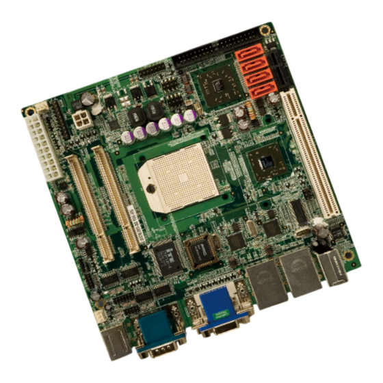
IEI Technology KINO-690S1 User Manual (229 pages)
Mini-ITX Motherboard with AMD Turion 64x2, Mobile Semprom CPU with VGA/DVI, USB 2.0, SATA II and Audio
Brand:
IEI Technology
| Category:
Motherboard
| Size: 7.14 MB
Table of Contents
Table of Contents
5
Packing List
4
1 Introduction
19
Overview
20
KINO-690S1 Features
20
Kino-690S1 Overview
20
KINO-690S1 Overview Photo
20
Figure 1-1: KINO-690S1 Overview [Front View]
21
Figure 1-2: External Peripheral Interface Connectors
21
KINO-690S1 Peripheral Connectors and Jumpers
22
Technical Specifications
23
Table 1-1: Technical Specifications
24
2 Detailed Specifications
25
Dimensions
26
Board Dimensions
26
Figure 2-1: KINO-690S1 Dimensions (MM)
26
Data Flow
27
External Interface Panel Dimensions
27
Figure 2-2: External Interface Panel Dimensions (MM)
27
Figure 2-3: Data Flow Block Diagram
28
Compatible Processors
29
DDR2 Memory Controller
29
Supported Processors
29
Figure 2-4: SO-DIMM Sockets
29
Amd 690G Northbridge Chipset
30
PCI Express Interface
30
Pcie X1 Expansion
30
Pcie Gbe Ethernet
31
Figure 2-5: Pcie X1 Expansion Slot
31
Processor Electrical Interfaces
30
Processor Power Management
30
Acceleration Features
32
Figure 2-6: Broadcom PCI Gbe Controllers
32
Display Support
33
TV out
33
DVI
34
Multiple Display Features
34
Amd Sb600 Southbridge Chipset
34
A-Link Xpress II Interface to the Northbridge
34
CPU Interface
34
PCI Host Bus Controller
35
Figure 2-7: PCI Expansion Slot
35
Figure 2-8: USB Connectors
36
USB Controllers
36
DMA Controller
37
Interrupt Controller
37
LPC Host Bus Controller
37
Smbus Controller
37
Figure 2-9: SATA Connectors
38
SATA II AHCI Controller
38
AC Link Interface
39
Figure 2-10: IDE Connector
39
IDE Controller
39
Figure 2-11: Audio Codec and Audio Jacks
40
Timers
41
Hardware Monitor
42
Power Management
42
RTC (Real Time Clock)
42
Lpc Bus Components
43
BIOS Chipset
43
LPC Bus Overview
43
Figure 2-12: LPC BUS Components
43
Super I/O Chipset
44
Super I/O 16C550 Uarts
45
Super I/O Enhanced Hardware Monitor
45
Super I/O Fan Speed Controller
45
Super I/O Keyboard and Mouse Controller
45
Super I/O LPC Interface
45
Super I/O Infrared
46
TPM Module
44
Environmental and Power Specifications
46
System Monitoring
46
Operating Temperature and Temperature Control
47
Power Consumption
48
Table 2-1: Power Consumption
48
Serial Port Chipset
46
3 Unpacking
49
Anti-Static Precautions
50
Unpacking
50
Unpacking Precautions
50
Unpacking Checklist
51
Package Contents
51
Table 3-1: Package List Contents
52
Optional Items
53
Table 3-2: Package List Contents
53
4 Connector Pinouts
55
Peripheral Interface Connectors
56
KINO-690S1 Layout
56
Figure 4-1: Connector and Jumper Locations
56
Table 4-1: Peripheral Interface Connectors
57
External Interface Panel Connectors
58
Internal Peripheral Connectors
58
ATX Power Connector
58
Table 4-2: Rear Panel Connectors
58
Digital Input/Output (DIO) Connector
59
Table 4-3: ATX Power Connector Pinouts
59
Fan Connector (+12V)
60
Figure 4-2: ATX Power Connector Pinout Locations
59
Table 4-4: DIO Connector Connector Pinouts
60
Figure 4-3: DIO Connector Connector Locations
60
Table 4-5: +12V Fan Connector Pinouts
61
Figure 4-4: +12V Fan Connector Location
61
Front Panel Connector (14-Pin)
61
Table 4-6: Front Panel Connector Pinouts (14-Pin)
62
Figure 4-5: Front Panel Connector Pinout Locations (14-Pin)
62
Figure 4-6: IDE Device Connector Locations
63
IDE Connector (40-Pin)
63
Infrared Interface Connector (5-Pin)
64
Table 4-7: IDE Connector Pinouts
64
Table 4-8: Infrared Connector Pinouts
65
Figure 4-7: Infrared Connector Pinout Locations
65
PCI Slot
65
Figure 4-8: PCI Slot Location
67
Table 4-9: PCI Slot
69
PCI Express X1 Slot
70
Figure 4-9: PCI Express X1 Slot Locations
71
Table 4-10: PCI Express X1 Slot Pinouts
72
Figure 4-10: SATA Drive Connector Locations
72
SATA Drive Connectors
72
Table 4-11: SATA Drive Connector Pinouts
73
Figure 4-11: Serial Connector Pinout Locations
73
Serial Port Connector (COM3)
73
Table 4-12: Serial Connector Pinouts
74
Figure 4-12: RS-232/422/485 Serial Port Connector Location
74
Serial Port Connector (COM4)(RS-232, RS-422 or RS-485)
74
Table 4-13: RS-232/RS-485 Serial Port Connector Pinouts
75
Trusted Platform Module (TPM) Connector
75
Figure 4-13: TPM Connector Pinout Locations
75
Table 4-14: TPM Connector Pinouts
76
TV out Connector
76
Figure 4-14: TV Connector Pinout Locations
76
Figure 4-15: USB Connector Pinout Locations
77
Table 4-15: TV Port Connector Pinouts
77
USB Connectors (Internal)
77
External Peripheral Interface Connector Panel
78
Audio Connector
78
Figure 4-16: KINO-690S1 External Peripheral Interface Connector
78
Table 4-16: USB Port Connector Pinouts
78
DVI and VGA Combo Connector
79
Figure 4-17: Audio Connector
79
Figure 4-18: DVI-D Connector Pinouts
80
Table 4-17: DVI-D Connector Pinouts
80
Keyboard/Mouse Connector
81
Figure 4-19: VGA Connector
81
Table 4-18: VGA Connector Pinouts
81
LAN Connectors
82
Figure 4-20: PS/2 Pinouts
82
Table 4-19: PS/2 Connector Pinouts
82
Figure 4-21: RJ-45 Ethernet Connector
83
Table 4-20: LAN Pinouts
83
Table 4-21: RJ-45 Ethernet Connector Leds
83
Serial Port Connectors (COM1 and COM2 )
84
USB Connector
84
Figure 4-22: Pinout Locations
84
Table 4-22: RS-232 Serial Port Pinouts
84
Table 4-23: USB Port Pinouts
85
5 Installation
86
Anti-Static Precautions
87
Installation Considerations
88
Installation Notices
88
Installation Checklist
89
Unpacking
90
Unpacking Precautions
90
Cpu, Cpu Cooling Kit and DIMM Installation
91
AMD Socket S1 CPU Installation
91
Figure 5-1: Make Sure the CPU Socket Retention Screw Is Unlocked
92
Cooling Kit CF-479B-RS Installation
93
Figure 5-2: IEI CF-479B-RS Cooling Kit
93
Figure 5-3: Cooling Kit Support Bracket
94
Figure 5-4: Connect the Cooling Fan Cable
94
Figure 5-5: SO-DIMM Installation
95
SO-DIMM Installation
95
Jumper Settings
96
Table 5-1: Jumpers
96
Clear CMOS Jumper
97
Table 5-2: Clear CMOS Jumper Settings
97
COM 4 Function Select Jumper
98
Table 5-3: COM4 Function Select Jumper Settings
98
Chassis Installation
99
Airflow
99
Figure 5-6: Clear CMOS Jumper
98
Figure 5-7: COM4 Function Select Jumper Location
99
Internal Peripheral Device Connections
100
Peripheral Device Cables
100
Table 5-4: IEI Provided Cables
100
Motherboard Installation
100
ATA Flat Cable Connection
101
Figure 5-8: IDE Cable Connection
101
Dual RS-232 Cable Connection
102
Figure 5-9: Dual RS-232 Cable Installation
102
Figure 5-10: SATA Drive Cable Connection
103
SATA Drive Connection
103
Figure 5-11: SATA Power Drive Connection
104
USB Cable (Dual Port)
104
Figure 5-12: Dual USB Cable Connection
105
USB Cable (Four Port)
105
External Peripheral Interface Connection
106
Figure 5-13: Four Port USB Cable Connection
106
Audio Connection
107
DVI Display Device Connection
107
Figure 5-14: Audio Connectors
107
LAN Connection (Single Connector)
108
Figure 5-15: DVI Connector
108
PS/2 Keyboard and Mouse Connection
109
Figure 5-16: LAN Connection
109
Serial Device Connection
110
Figure 5-17: PS/2 Keyboard/Mouse Connector
110
USB Connection (Dual Connector)
111
Figure 5-18: Serial Device Connector
111
VGA Monitor Connection
112
Figure 5-19: USB Connector
112
Figure 5-20: VGA Connector
113
6 Bios Screens
114
Introduction
115
Starting Setup
115
Using Setup
115
BIOS Menu Bar
116
Getting Help
116
Unable to Reboot after Configuration Changes
116
Table 6-1: BIOS Navigation Keys
116
Main
117
System Overview
117
Advanced
118
System Date [XX/XX/XX]
118
CPU Configuration
119
IDE Configuration
120
System Time [XX:XX:XX]
118
DE Master and IDE Slave
121
Menu 4: IDE Configuration
121
IDE Master, IDE Slave
122
Auto-Detected Drive Parameters
123
Onboard PCI IDE Controller [Both]
121
Menu 5: IDE Master and IDE Slave Configuration
123
Type [Auto]
124
Zip
124
Lba/Large Mode [Auto]
125
Block (Multi Sector Transfer) [Auto]
125
PIO Mode [Auto]
125
DMA Mode [Auto]
126
Auto]
127
32Bit Data Transfer [Enabled]
127
Super IO Configuration
128
Serial Port1 Address [3F8/IRQ4]
128
Serial Port1 Mode [Normal]
129
Serial Port2 Address [2F8/IRQ3]
129
Serial Port2 Mode [Normal]
129
Serial Port3 Address [3E8]
130
Select RS232 or RS422/RS485 [RS232]
130
Serial Port4 Address [2E8]
130
Hardware Health Configuration
131
ACPI Configuration
132
ACPI Version Features [ACPI V1.0]
132
Trusted Computing
133
Suspend Mode [S1(POS)]
133
TCG/TPM Support [Yes]
134
TPM Enable/Disable Status [No State]
134
TPM Owner Status [No State]
134
Menu 9: Trusted Computing
134
Remote Access Configuration
135
Remote Access [Disabled]
135
Serial Port Number
135
Serial Port Mode
136
Flow Control
136
Redirection after BIOS POST
136
Terminal Type
136
VT-UTF8 Combo Key Support
136
Sredir Memory Display Delay
136
Serial Port Number [COM1]
136
Base Address, IRQ [3F8H,4]
136
Serial Port Mode [115200 8,N,1]
136
Flow Control [None]
137
Redirection after BIOS POST [Always]
137
Terminal Type [ANSI]
137
USB Configuration
138
VT-UTF8 Combo Key Support [Disabled]
138
Sredir Memory Display Delay [Disabled]
138
USB 1.1 EHCI Controller [Enabled]
139
USB 2.0 EHCI Controller [Enabled]
139
Menu 11: USB Configuration
139
USB Mass Storage Device Configuration
140
Legacy USB Support [Enabled]
140
USB2.0 Controller Mode [Hispeed]
140
USB Mass Storage Reset Delay [20 Sec]
141
Menu 12: USB Mass Storage Device Configuration
141
Device
142
Emulation Type [Auto]
142
Pci/Pnp
143
Menu 13: Pci/Pnp Configuration
144
Clear NVRAM [No]
145
Plug & Play O/S [No]
145
PCI Latency Timer [64]
145
Allocate IRQ to PCI VGA [Yes]
146
Palette Snooping [Disabled]
146
PCI IDE Busmaster [Disabled]
146
Offboard PCI/ISA IDE Card [Auto]
147
IRQ# [Available]
147
DMA Channel# [Available]
148
Boot
149
Reserved Memory Size [Disabled]
149
Boot Settings Configuration
150
Quick Boot [Enabled]
151
Quiet Boot [Disabled]
151
Menu 15: Boot Settings Configuration
151
Boot Device Priority
152
PS/2 Mouse Support [Enabled]
152
Boot from LAN Support [Disabled]
152
Hard Disk Drives
153
Menu 17: Hard Disk Drives
154
CD/DVD Drives
155
Security
156
Change Supervisor Password
157
Change User Password
157
Menu 19: Security
157
Chipset
158
Boot Sector Virus Protection [Disabled]
158
Northbridge Chipset Configuration
159
Menu 21:Northbridge Chipset Configuration
160
ECC Configuration
161
DRAM ECC Enable [Enabled]
161
4-Bit ECC Mode
161
DRAM SCRUB REDIRECT [Disabled]
162
DRAM BG Scrub [Disabled]
162
L2 Cache BG Scrub [Disabled]
162
Internal Graphics Configuration
163
L1 Cache BG Scrub [Disabled]
163
Internal Graphics Mode [UMA]
164
BIOS Menu 23: Internal Graphics Configuration
164
UMA Buffer Size [Auto]
165
Current UMA Buffer Size [Auto]
165
Primary Video Controller [IGFX]
165
TV Standard
165
Southbridge Configuration
166
Expansion Mode [Disabled]
166
AC97 Audio Device
167
Set Spread Spectrum Function [Disabled]
167
Menu 24:Southbridge Chipset Configuration
167
Power
168
Onchip SATA [Enabled]
168
Onchip SATA Type [Enabled]
168
Power Management/Apm [Enabled]
169
Power Button Mode [On/Off]
169
Menu 25:Power
169
Resume on Ring [Disabled]
170
AT/ATX Power [ATX]
170
Restore on AC Power Loss [Last State]
170
Exit
171
Resume on RTC Alarm [Disabled]
171
RTC Alarm Date (Days)
171
System Time
171
Save Changes and Exit
172
Discard Changes and Exit
172
Discard Changes
172
Menu 26:Exit
172
Load Optimal Defaults
173
7 Software Drivers
174
Available Software Drivers
175
Driver CD Auto-Run
175
Figure 7-1: Introduction Screen
176
Figure 7-2: Available Drivers
176
Amd 690G Chipset Driver Installation
177
Figure 7-3: Chipset Driver Installation Program
177
Figure 7-5: Chipset Driver Installation License Agreement
178
Figure 7-4: Chipset Driver Installation Welcome Screen
178
Figure 7-6: Select Destination Folder
179
Figure 7-7: Chipset Driver Installing Screen
179
Figure 7-8: Welcome Screen
180
Figure 7-9: Chipset Driver Readme File Information
180
Figure 7-10: Chipset Driver Installation Complete
181
Broadcom LAN Driver (for Gbe LAN) Installation
182
Figure 7-11: Setup Complete
182
Figure 7-12: Windows Control Panel
183
Figure 7-13: System Icon
184
Figure 7-14: Device Manager Tab
184
Figure 7-15: Device Manager List
185
Figure 7-16: Search for Suitable Driver
186
Figure 7-17: Locate Driver Files
186
Realtek Ac`97 Audio Driver (Alc655) Installation
187
BIOS Setup
187
Driver Installation
187
Figure 7-18: Location Browsing Window
187
Figure 7-19: Select the Audio CODEC
188
Figure 7-20: Locate the Setup Program Icon
189
Figure 7-21: Preparing Setup Screen
189
Figure 7-22: Installshield Wizard Welcome Screen
190
Figure 7-23: Audio Driver Software Configuration
190
Figure 7-24: Audio Driver Digital Signal
191
Figure 7-25: Audio Driver Installation
191
Figure 7-26: Restart the Computer
192
Webpam RAID Utility Driver Installation
192
Figure 7-27: Chipset Driver Installation Program
193
Figure 7-28: Chipset Drivers
193
Figure 7-29: RAID Utility Icon
194
Figure 7-30: SATA RAID Setup Program Icon
194
Figure 7-31: Welcome Screen
195
Figure 7-32: Webpam License Agreement
195
Figure 7-33: Select Webpam Installation Destination
196
Figure 7-34: Webpam Ready to Install
196
Figure 7-35: Webpam Installation
197
Figure 7-36: Webpam Installation Complete
197
Abios Options
198
Appendix A
199
Bdio Interface
203
Dio Interface Introduction
204
Dio Connector Pinouts
204
Assembly Language Samples
205
Enable the DIO Input Function
205
Enable the DIO Output Function
205
Cwatchdog Timer
206
Daddress Mapping
209
Address Map
210
St Mb Memory Ddress Ap
212
Addres Map
212
Irq Mapping Table
213
Hazardous Materials Disclosure
214
Hazardous Material Disclosure Table for IPB Products Certified as Rohs Compliant under 2002/95/EC Without Mercury
215
Fraid Setup
218
Introduction
219
Precautions
219
Features and Benefits
220
Accessing the Amd Sb600 Raid Utility
220
Gindex
224
Advertisement
Advertisement
Related Products
IEI Technology KINO-690AM2
IEI Technology KINO-6612LVDS
IEI Technology KINO-6612
IEI Technology KINO-6614
IEI Technology KINO-QM670
IEI Technology KINO-9152G4
IEI Technology KINO-9451
IEI Technology KINO-9652
IEI Technology KINO-G410T-R10
IEI Technology KINO-SE-i2
IEI Technology Categories
Motherboard
Touch Panel
Computer Hardware
Single board computers
Desktop
More IEI Technology Manuals
Login
Sign In
OR
Sign in with Facebook
Sign in with Google
Upload manual
Upload from disk
Upload from URL