Table of Contents
Advertisement
Quick Links
Advertisement
Table of Contents

Related Manuals for Dedicated Micros Oracle


Summary of Contents for Dedicated Micros Oracle
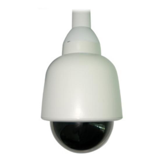
- Page 1 Oracle Dome Camera Installation Manual www.dedicatedmicros.com...
-
Page 2: Table Of Contents
Dome Configuration ..........24 Troubleshooting ..........25 Notes ..............26 Whilst every attempt is made to ensure these manuals are accurate and current, Dedicated Micros reserve the right to alter or modify the specification of the machine described herein without prejudice. Dedicated Micros ©2008... -
Page 3: Introduction
Introduction Congratulations on choosing a Dedicated Micros Oracle dome camera. This manual will provide all the necessary information to install the Dedicated Micros Oracle Dome Camera. RF Interference warning This is a class A product. In a domestic environment this product may cause radio frequency interference, in which case the user may be required to take adequate measures. -
Page 4: Camera Care
• EN 60825-1 Safety standard for LED’s and Lasers. Further details about these applicable standards can be obtained from Dedicated Micros Ltd. 1200 Daresbury Park, Daresbury, Cheshire, WA44HS. A “Declaration of Conformity” with all relevant European Union Directives has been made, is on file and is available from the Dedicated Micros address above. -
Page 5: Components Supplied - External
Before installing the dome, please remove the components from the packaging and verify that all items listed below have been supplied: 1 x Dedicated Micros Oracle Dome enclosure and camera (with incorporated safety bond) 1 x Oracle Dome Power Supply (except USA) -
Page 6: Components Supplied - Internal
Before installing the dome, please remove the components from the packaging and verify that all items listed below have been supplied: 1 x Dedicated Micros Oracle Dome enclosure and camera (with incorporated safety bond) 1 x Dedicated Micros Oracle Dome manual... -
Page 7: Electrical Connections - External
Earth Green/Yellow Earth Coax Video Signal Coax Vid Screen Yellow RS485A Green RS485B Brown 24VAC Blue 24VAC Violet Alarm 1 Pink Alarm 2 Grey Alarm 3 Orange Alarm 4 Black Alarm Ground White Relay A Relay B Dedicated Micros ©2008... -
Page 8: Minimum Configuration
RS485B connects to Pin 9 on the serial connector of the DVR. Alternatively the Oracle supports either up the coax (UTC) control via the video output BNC connector or un-shielded twisted pair (UTP) via the UTP video/UTP net connectors (available via future software upgrade). -
Page 9: Electrical Connections - Internal
Pin 1 on Serial Connection to appropriate DVR 485B Pin 9 on Serial Connector to appropriate DVR Vid GND BNC Earth (screen connection) Vid Sig BNC Signal (centre pin connection) Note: Refer to ‘Dome Configuration’ for a list of appropriate DVRs. Dedicated Micros ©2008... -
Page 10: Mounting Configurations - External
Snowdrop mount bracket (order code DM/90004) for mounting at the top of a pole or column. Pendant Mount (order code DM/90003 - 250mm; order code DM/90012 - 500mm; order code DM/90013 - 1000mm; order code DM/90014 - 1500mm) for roof or parapet mounting. Dedicated Micros ©2008... -
Page 11: Safety Bond
Attach bond to a suitable secure position in the ceiling void. Note: Always support dome with bond prior to mating connector. The weight of dome should be supported by bond ensuring no stress is placed on centre connector at any time. Dedicated Micros ©2008... -
Page 12: Dome Mounting
Mate the previously prepared central connector, refer to ‘Electrical Connections’ for more information, supplying power & control to dome (ensure power is off when connecting). Tighten 4 top mounting fixings with Hexagonal key supplied to secure. Secure any plastic covers or trim (wall/pendant installations only). Dedicated Micros ©2008... -
Page 13: Mounting Configurations - Internal
Corner Bracket (order code DM/90007) for mounting to corners of buildings in conjunction with DM/90002. Tile mount (order code DM/CSD/TMR) for suspended ceilings. Snowdrop mount bracket (order code DM/90004) for mounting at the top of a pole or column. Dedicated Micros ©2008... - Page 14 Attach bond to a suitable secure position in the ceiling void. Note: Always support dome with bond prior to mating connector. The weight of dome should be supported by bond ensuring no stress is placed on centre connector at any time. Dedicated Micros ©2008...
- Page 15 Mate the previously prepared central connector, refer to ‘Electrical Connections’ for more information, supplying power & control to dome (ensure power is off when connecting). Tighten 4 top mounting fixings with Hexagonal key supplied to secure. Secure any plastic covers or trim (wall/pendant installations only). Dedicated Micros ©2008...
- Page 16 Fasten the dome to the mounting ring (B) using the provided 3 x No.8x1”(25.4mm) self tapping screws (D) (or suitable fixings provided by the installer). Snap fit the provided tile mount bezel (E). This replaces the standard bezel (F) provided with the camera. Discard the standard bezel (F). Dedicated Micros ©2008...
-
Page 17: Control Configuration - All Models
Auto Sense (under development) DM UTC (under development) DM RS485 DM Current Loop (under development) BBV UTC Note: The selected protocol will be displayed on screen at power-up for a few seconds each time the rotary switches are changed. Dedicated Micros ©2008... - Page 18 ‘RS485 Serial Connection’. TERMINATION SWITCH LOCATION (SW1) Note: SW1 should be set towards the centre of PCB to turn RS485 termination ON or set away from the centre of the PCB to turn RS485 termination OFF. Dedicated Micros ©2008...
-
Page 19: Rs485 Serial Connection
RS485 protocol allows multiple domes to be connected via the serial connection on the back of the DVR. Each dome in the chain should have a unique individual address, to enable it to be called by the DVR. The switch settings for the protocols and node addresses are shown in the table below. Dedicated Micros ©2008... - Page 20 (in the example above) “Node Address 05”. It will also display briefly after each time the setting is changed. All Dedicated Micros Oracle domes are fitted with a termination switch (SW1), shown above. If a single dome is connected on the RS485 line, or if a star configuration is used, the termination switch should be switched to ‘ON’...
-
Page 21: Up-The-Coax Ptz Control
Note: The serial connection is not required when using Up-The-Coax control. Up the Coax Switch Settings Switch Setting Yellow/Blue Not required. RED SWITCH LOCATION BLUE SWITCH LOCATION YELLOW SWITCH LOCATION Dedicated Micros ©2008... -
Page 22: Upgrading Dome Software
Upgrading Dome Software The Oracle dome has an expanded feature and control set over other domes, which are only available through the Dedicated Micros PTZ protocol. These features are accessed through a set of web pages available on the latest Dedicated Micros machines (DV-IP Server, DV-IP RT, DV-IP HD and HighVu Excel) and that will have access to this dome. - Page 23 RS485B. If the converter used is different then an intermediate cable may be needed to transpose the wires (see converter’s documentation for pin out details). Confirm the upgrade has been successful by checking the software version number on the startup screen (This screen can also be displayed by special preset G4) Dedicated Micros ©2008...
-
Page 24: Dome Configuration
Patrols. along with Camera and Event settings. Some of these will be available to standard DVR’s. List of DVR’s required to utilise advanced programming features • DV-IP Server, DV-IP HD, DV-IP RT and HighVu Excel running Gen3 pages. Note: Standard functionality will still be available with all other control equipment. Dedicated Micros ©2008... -
Page 25: Troubleshooting
Cause This is most likely due to too much or too little video gain whilst using UTC telemetry. Solution Adjust using the Oracle dome settings page on the DVR. Dome spins continuously (DM controllers) Cause No joystick dead band recognized as joystick was off centre during power-up. -
Page 26: Notes
Notes Dedicated Micros ©2008... - Page 27 COAX OR DIFFERENTIAL VIDEO SWITCH LOCATION (SW3) ..............19 Components supplied - External ........................5 Components supplied - Internal........................6 Connecting the DVR to the Oracle Dome (via PCB) ..................8 Control Configuration - All Models ....................... 17 Dome Configuration............................. 24 Dome connector ............................
- Page 28 Neckarstrafle 15, 14434 Albemarle Point Place, Suite 100, 41836 Hückelhoven, Germany Chantilly, Virginia 20151 USA Dedicated Micros France Dedicated Micros, Australia PTY. 9-13 rue du Moulinet 5/3 Packard Avenue, Castle Hill, 75013 Paris, France NSW 2154, Australia Dedicated Micros Slovenia...
Need help?
Do you have a question about the Oracle and is the answer not in the manual?
Questions and answers