Table of Contents
Advertisement
Quick Links
Advertisement
Table of Contents

Related Manuals for MIMAKI GP-604D


Summary of Contents for MIMAKI GP-604D
- Page 1 OPERATION MANUAL MIMAKI ENGINEERING CO., LTD. TKB Gotenyama Building, 5-9-41, Kitashinagawa, Shinagawa-ku, Tokyo 141-0001, Japan Phone: +81-3-5420-8671 Fax: +81-3-5420-8687 URL: http: // www.mimaki. co. jp / E-mail: traiding@mimaki.co.jp D201172...
- Page 3 ING CO., LTD. has been informed of the possible risk of such damages in prior. For example, MIMAKI shall not be liable to any damage to medium (works) due to the use of the product or any indirect damage that is caused by a product that is manufactured with damaged medium.
- Page 4 Operation of this equipment in a residential area is likely to cause harmful interference in which cause the user will be required to correct the interference at his own expense. • In the case where MIMAKI-recommended cable is not used for connection of this device, limits provided by FCC rules can be exceeded.
-
Page 5: Foreword
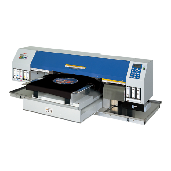
Foreword Thank you for purchasing our ink-jet plotter ‘‘GP-604D’’ for T-shirt printing. ‘‘GP-604D’’ is capable of discharging color of the printed portion by directly printing our special discharge liquid to the T-shirts. Further, with the use of special pigment printing ink, it can perform the color printing, too. -
Page 6: Features
Features The features of the device are described below. Use of discharge liquid It is possible to discharge color of the printed portion by printing special discharge liquid directly to T-shirts and making heat-treatment. *Discharging of color is different depending on the dyestuff used for the ground dyeing. Printing pigment ink The device is designed for printing directly on T-shirts and other media using printing pigment ink of high light stability. -
Page 7: For Safe Operation
For safe operation Pictorial signs Pictorial signs are used in this Operation Manual for safe operation of and in prevention of damages to the device. Pictorial signs and their meanings are given below. Read and fully understand before reading the text. •... - Page 8 Store ink cartridges and waste ink tank in a place that is out of the reach of chil- dren. • Never refill the ink cartridge with ink. MIMAKI assumes no responsibility for malfunction caused by using the device after replenishment of ink. • Never disassemble or remodel the ink cartridge. Disassembling will result in electric shocks or breakdown of the device.
-
Page 9: Never Do The Following
Never Do the Following WARNING Do not disassemble or remodel the device. Heater • Never disassemble or remodel • Keep combustibles such as dust or the main unit of the printer and stain clear out of the heater on the the ink cartridge. -
Page 10: Precautions In Installation
Precautions in installation CAUTION A place that is not horizontal A place exposed to direct sunlight A place in which temperature and humidity A place that vibrates vary by a great margin Use the device under the following environment. Operating environment: 20 to 35°C 35 to 65% (Rh) A place exposed to direct air blow from air... -
Page 11: Precautions In Use
Use the ink specified • It is strongly recommended to use • Use the GP-604D genuine ink. the device in a room that is not The plotter does not operate dusty. Set the Refresh level 2 or with other ink than the GP-604 3 when in bad environment. - Page 12 CAUTION Ink cartridges Heater • If the ink cartridge is moved from • Do not spill liquid on the table a cold place to a warm place, as this may cause failure of the leave it in the room temperature heater or ignition.
-
Page 13: Table Of Contents
TABLE OF CONTENTS Foreword ........................ i On This Operation manual ........................ i Features ......................... ii Use of discharge liquid ........................ii Printing pigment ink ......................... ii Use of area plate ..........................ii For safe operation ....................iii Pictorial signs ..........................iii Example of pictorial signs ....................... - Page 14 Print the test pattern ........................2.8 If printed abnormal pattern ......................2.9 Setting Garment (T-shirt) ................. 2.10 Set the area plate ......................... 2.11 Remove the area plate ......................... 2.13 Read the thickness of the garment (T-shirt) ............. 2.14 Plotting an Image from source data ..............2.15 Perform the printing ( Same operations both for color printing and discharging ) .....
- Page 15 When the message [REPLACE WIPER] is displayed [STATION]-[WIPER EX- CHANGE] ......................5.5 Adjusting between the two plotting directions [PRINT ADJUST] ....... 5.7 If nozzles are clogged even after the cleaning function is executed ....5.9 Cleaning the nozzle [NOZZLE WASH] ..................5.9 [FILL UP INK] ...........................
-
Page 16: How To Read This Operation Manual
How to read this operation manual Display on the LCD and Indication of the Keys In this Operation manual, the characters displayed on the LCD of the operation panel and the keys used to operate the device are explained, together with the operation procedure. page 1.4 Operate the device while confirming the display on the LCD. -
Page 17: Structure Of This Operation Manual
Structure of this Operation manual This manual consists of the following seven chapters to describe the handling of the device. Chapter 1 Name and Function of each section This chapter describes the name and function of the device. Chapter 2 Operations This chapter describes a series of operations and settings, ranging from power-on to end of plotting. - Page 18 - xiv -...
- Page 19 CHAPTER 1 Name and Function of each section This chapter describes the name and function of each section of the device. Table of contents The Front ........................1.2 The Rear ........................1.3 Operation Panel ......................1.4 Carriage ........................1.5 Heater ........................1.6 Setting the heater voltage ..................
-
Page 20: The Front
The Front Name Function Front cover Protects the station from dusts. Open the cover when performing maintenance. Carriage Moves the print head from side to side. Changeover valve of Changes the supply of discharge liquid/Cleaner to discharge liquid head. discharge liquid/Cleaner page 1.9 Power switch It turns on/off the power to the device. -
Page 21: The Rear
The Rear Name Function IEEE-1394 connector Interface connector compatible with IEEE-1394. IEEE-1284 connector Not used on the device. Voltage selector switch Switches between 100-120 V and 220-240 V according to the power voltage used. page 1.7 Name Function AC inlet Connects the power cable. -
Page 22: Operation Panel
Operation Panel The operation panel that is used to operate the device. Display POWER lamp Displays a set item, a guidance Lights up (in green) when the error, etc. power to the device is turned on. Z keys Adjust the head height in the JOG keys [ ] [ ] [ ] [ ] LOCAL mode. -
Page 23: Carriage
Carriage The carriage is provided with changeover valves of printing ink head and discharging ink head and discharge liquid and Cleaner to ink head for discharge. Further, it is provided with a sensor to read the thickness of the media (T-shirt), and LED pointer to determine the starting point of printing. -
Page 24: Heater
Heater The table is heater built-in. Provide appropriate temperature by the heater to prevent the ink from coming though the wrong side. It also enables to increase the coloring effect. The heater status indicated with the LED indicator. When turned off the device power, the heater power is also turned off. •... -
Page 25: Setting The Heater Voltage
Setting the heater voltage The heater voltage must be set to the source voltage of the plotter using the voltage selectors located on the back of the plotter. For safety reasons, the plotter is set to 220V for shipment. • The plotter may be damaged if it is plugged to a 200-240V source while the voltage selector is set to 110V. -
Page 26: Ink Station
Ink station The carriage has 2 heads for color and 1 head for discharge, totaling 3 heads. Each head is provided with 2 lines of nozzles. The head for color has one color-ink corresponding to 1 line of nozzle. The head for discharge has discharge liquid corresponding to 2 lines of nozzles. To the ink station, each one color of ink cartridge, two Cleaner and 2 discharge liquid totaling 8 cartridges are set. -
Page 27: Initial Filling Of Ink
Initial filling of ink Operations when the device is started for the first time. When this device is started for the first time, turn the “Discharge liquid/Cleaner changeover valves” on the front of the carriage to supply discharge liquid to the head for discharge liquid. Left-side changeover valve Right-side... - Page 28 9. Cleaning fluid is filling up. PLEASE WAIT 10. Turn the left side valve to ‘‘CLOSE’’. Left Valve Set < CLOSE > 11. Press the [ENTER] key. 12. Turn the right side valve to ‘‘WASH’’. Right Valve Set < WASH > 13.
- Page 29 PLEASE WAIT 25. Turn the left side valve to ‘‘DCG’’. Left Valve Set < DCG > 26. Press the [ENTER] key. 27. Initial filling is completed. < LOCAL > width : 610mm • If the discharge head left filled with discharge liquid, the life of the discharge head will be shortened.
-
Page 30: Menu Mode
MENU mode There are the following three mode in this device. LOCAL mode This is the mode after the initial performance. All keys are effective to enable setups. The device is able to receive data from computer, however, it will not perform plotting. In this mode, it is possible to perform the following operations. - Page 31 CHAPTER 2 Operation This chapter describes basic operations for setting and printing. Table of contents Operation ....................... 2.2 Switching on the power supply ..............2.3 Filling of discharge liquid at the time of starting works ........2.4 Front cover ....................2.6 Adjusting the suitable temperature of heater..........
-
Page 32: Operation
Operation The following shows a series of operations and settings, ranging from power-on to end of plotting. GP-604D Operation RasterLink GP Operation “RasterLink GP” is an output software attached to the device. For details, refer to “RasterLink GP Connect the computer to the plotter Operation Manual”. -
Page 33: Switching On The Power Supply
As turning on the power, a buzzer sounds before performing the initiate operation. Carefully handle with the moving device. GP-604D V X.XX When the power is on, the LCD first displays “BOOT” and then subsequently displays the firmware version number. -
Page 34: Filling Of Discharge Liquid At The Time Of Starting Works
Filling of discharge liquid at the time of starting works In order to prevent the shortening of the life of the head for discharge liquid, the discharge liquid contained is replaced by Cleaner when it is not used for an extended period of time. At the time of starting works, the Cleaner filled in the head for discharge liquid is to be drained and the discharge liquid is filled in. - Page 35 14. The right valve is filling discharge FILL UP PLEASE WAIT liquid. Wait for about 1 minute. 15. Turn the left valve to ‘‘DCG’’. Left Valve Set < DCG > 16. Press the [ENTER] key. 17. The left valve is filling discharge FILL UP PLEASE WAIT liquid.
-
Page 36: Front Cover
Front cover Opening/closing the front cover • Keep the front cover closed during plotting operation. In that case, it interrupts image plotting and disables continuous processing. • Do not directly open/close the front cover by holding the plastic cover, or it may damage the device. -
Page 37: Adjusting The Suitable Temperature Of Heater
Adjusting the suitable temperature of heater Before turning on the heater power, set the appropriate temperature for the garment in use. • Do not touch the heater part for the part (on the table) is heating up while the heater is on, or it may cause burns. •... -
Page 38: Checking And Solving Nozzle Clogging
Checking and solving nozzle clogging Before printing on media (T-shirt), print a test pattern on thermal paper. Perform test plotting to check whether there is nozzle clogging or other plotting failures. If the test pattern shows any sign of abnormal conditions, carry out the cleaning function. •... -
Page 39: If Printed Abnormal Pattern
If printed abnormal pattern STEPS: 1. Press the [CLEANING] key. CLEANING TYPE : normal 2. Select the head to be cleaned pressing the jog CLEANING keys [ ] and [ ]. HEAD : color CLEANING color Cleans only those heads in which K.C.M.Y HEAD : dcg ink is filled. -
Page 40: Setting Garment (T-Shirt)
Setting Garment (T-shirt) Set the garment flatly after getting rid or wrinkles. • Do not touch the heater part for the part (on the table) is heating up while the heater is on, or it may cause burns. • Make sure to use the garment after getting rid of wrinkles and curls, or it may cause the image failure. -
Page 41: Set The Area Plate
Set the area plate STEPS: 1. Set the area plate on the table. Adjust two convex portions for positioning on the back left of the area plate to 2 holes for positioning on the table and set it on the table. Area plate Convex portion for positioning (Rear side) - Page 42 3. Place the T-shirt on the area plate. Place T-shirt on the area plate. Put the portion of T-shirt running over the table into the sleeve tray on each side of the table. Area mark T-shirt (screen printing) Area plate position Sleeve tray (Left side) Sleeve tray (Right side) •...
-
Page 43: Remove The Area Plate
Remove the area plate STEPS: 1. Put fingers from the lower side into two holes on the front side of the table and push the area plate up and float it . Area plate Two fingers are put in from the front side. Table •... -
Page 44: Read The Thickness Of The Garment (T-Shirt)
Read the thickness of the garment (T-shirt) The device reads the thickness of the garment (T-shirt) and the head moves according to the thickness. STEPS: 1. Press the [REMOTE] key to revert the LOCAL < LOCAL > mode. width : 610 mm 2. -
Page 45: Plotting An Image From Source Data
Plotting an Image from source data Perform the printing ( Same operations both for color printing and discharging ) The following describes the mode selection for data reception from the computer and LCD display during plotting. For various function settings necessary for plotting, refer to “CHP4 Setting Function”. When plotting is started, the LCD displays the following information. -
Page 46: Interrupting The Plotting Operation
Interrupting the plotting operation To interrupt the plotting operation, stop the carriage and erase the receive data from the device. If not erasing the receive data, the plot operation is performing from the interrupt data in the RE- MOTE mode. STEPS: 1. -
Page 47: Heat With A Press
Heat with a press Place the garment (T-shirt) on the pressing machine to settle the ink. • Avoid contact of printed area with the white area. The wet ink may smear the white area. • Use a special pressing machine. Extra-high temperature may burn the material. - Page 48 2. Wash the media (T-shirt). The printed and pressed media (T-shirt) is washed by washing machine as you wash the normal T-shirts. • As the heat-pressed media (T-shirt) contains residual formaldehydes, a harmful substance, make sure to wash the media (T-shirt) to eliminate formaldehyde.
-
Page 49: To Replenish Ink, Set A New Ink Cartridge In The Ink Station
To replenish ink, set a new ink cartridge in the ink station If ink in the cartridge comes to an empty, the corresponding message appears. Plotting can be continued, however ink may run out during plotting. Immediately put a new ink cartridge. •... - Page 50 Confirm the remaining ink This function enables to confirm the remaining amount of ink. STEPS: 1. Press the [ENTER] key in the LOCAL mode. < LOCAL > The remaining amount of ink is displayed with a number width : 610 mm from 1 to 9.
-
Page 51: Filling Of Cleaner At The End Of The Works
Filling of Cleaner at the end of the works If you leave the head for discharge liquid with discharge liquid filled in for a long time, the life of the head for discharge liquid will be shortened because the discharge liquid melts the water-shedding part. - Page 52 14. The right valve is filling Cleaner. FILL UP PLEASE WAIT Wait for about 1 minute. 15. Turn the left valve to ‘‘WASH’’. Left Valve Set < WASH > 16. Press the [ENTER] key. 17. Both right and left valves are filling FILL UP PLEASE WAIT Cleaner.
-
Page 53: Turning The Power Off
Turning the power off When plotting is completed, press the power switch on the front face to turn the power off. To turn the power off, check first whether or not there is data received and there remains data that has not yet been output in the device. - Page 54 - 2.24 -...
-
Page 55: Chapter 3 Daily Cleaning
CHAPTER 3 Daily cleaning This chapter describes daily cleaning. Table of contents Daily Maintenance ..................3.2 Cleaning the wiper and ink caps ..............3.4 When the waste ink tank becomes full ............3.6 - 3.1 -... -
Page 56: Daily Maintenance
Daily Maintenance Make sure to conduct maintenance works for the device when necessary or periodically so as to use the device for a long time while keeping its plotting accuracy. Notes on cleaning • Never disassemble the device. Disassembling the device may result in electric shock hazards and breakage of the device. -
Page 57: If The Frame Components Of The Device/Table/T-Shirt Plate Have Stained
If the frame components of the device/table/T-shirt plate have stained Dampen a piece of soft cloth with water or neutral detergent diluted with water, squeeze it and wipe the frame components clean. - 3.3 -... -
Page 58: Cleaning The Wiper And Ink Caps
Cleaning the wiper and ink caps Ink cap prevents clogging of the head nozzle caused by the dried nozzle. Wiper wipes out ink adhered to the head nozzle. As the device is used to plot images, the wipers and ink caps gradually become stained with ink and dust. - Page 59 9. Clean the used wiper with water, and dry it. • If dirts or curl is serious, replace the wiper with a new one. At the time of replacement, make sure to terminate the plotter operation and follow the wiper replacement procedure. page 5.5 10.
-
Page 60: When The Waste Ink Tank Becomes Full
When the waste ink tank becomes full Waste ink used for cleaning the heads gathered in the waste ink tank. When the gathered waste ink exceed the marker line on the tank, immediately replace the tank with a new waste ink tank. •... - Page 61 CHAPTER 4 Setting Function This chapter describes operations and setting necessary for plotting. Table of contents Basic operations of menus ................4.2 Register the function on each purpose (Type Registration) ......4.4 Setup functions....................4.5 Effective Plotting Area ................. 4.10 Set the ORIGIN ...................
-
Page 62: Basic Operations Of Menus
Basic operations of menus This section describes how to change over the operation modes and how to operate the menus. The following gives the key operation flow to invoke menus. For details, refer to Appendix. REMOTE < LOCAL > ∗ REMOTE ∗ width : 610 mm TYPE. - Page 63 1. Select the LOCAL mode. Ascertain first that the device does not perform printing in the REMOTE mode, then press the [REMOTE] key to enter the LOCAL mode. 2. Select the FUNCTION mode. Press the [FUNCTION] key, and the device enters the FUNCTION mode. The FUNCTION mode is divided into two categories: the setup function and maintenance func- tion.
-
Page 64: Register The Function On Each Purpose (Type Registration)
Register the function on each purpose (Type Registration) The FUNCTION mode consists of 13 items. The 13 items can be registered for the following four types. It enables to change plotting conditions easily as usage. Registering a type 1. Make sure that the mode is LOCAL mode. <... -
Page 65: Setup Functions
Setup functions List of functions The list below shows the detail information on each function. Name Function page 4.6, A-10 FEED COMP Correct the amount of garment feed in printing. page 4.6, A-10 HEATER Set condition of the built-in heater. page 4.7, A-10 PRINT MODE Set the plot quality, plot direction, and logical seek. - Page 66 FEED COMP. page A.10 When the garment type or heater temperature is changed, be sure to correct the amount of feed. (-255 -255) page 4.17 HEATER page A.10 Set the built-in heater. PRINT HEAT : (Temperature setting page 2.5) Sets the heater temperature. (OFF, 20- 60 C / 68- 140 Switches the unit of temperature.
- Page 67 PRINT MODE page A.10 Set the plot quality, plot direction, and logical seek. QUALITY : Select the quality image from three items. (STANDARD, FINE, FAST) DIRECTION : Specifies the head movement direction for plotting. [UNI-D] plots an image while the head is moving to the left. [BI-D] plots an image while the head is moving to the left and right.
- Page 68 INK LAYERS page A.11 When the color development is poor in color printing, or when the discharge of color is poor in discharge printing, set the number of overprinting. (1-9 times) DRYING TIME page A.11 Set the ink drying time. The drying time is the time interval in every scan.
- Page 69 STAMP page A.12 Print the date of output and plotting condition at end of plotting. MODE STAMP : Print the plotting condition. (ON, OFF) TIME STAMP : Print the date of output. (ON, OFF) AUTO CLEANING page A.12 Perform head cleaning automatically. Perform cleaning for each plot to prevent plotting failures. (ON, OFF) WORK CHANGE page A.12...
-
Page 70: Effective Plotting Area
Effective Plotting Area The device enables to print over the black bordered table area. Printing direction TABLE 420 mm 610 mm Maximum print area : 420 x 610 mm * In case printing at 360x360 dpi, 360x540 or 360x720 dpi in a high speed mode, the maximum print area is to be 420x570 (mm). -
Page 71: Set The Print Area
Set the print area This device enables to specify the print area as following two methods. page 4.9 Two methods (POINT/AREA) are able to switch with the function [LED POINTER]. The specified print area is read by RasterLinkGP (output software) and output data are created accordingly. - Page 72 2. AREA - Specify the printing area - Specify two point (P1, P2) to determine the printing point. 1. Specify the base point (P0). 2. Specify two point (P1, P2) to determine the printing area. A rectangle formed by the two opposing corners indicates the printing area. P0 : Base point Effective printing area : Rectangle area determined by P1 and P2.
- Page 73 STEPS: 1. Make sure that the mode is LOCAL mode. <LOCAL> Width : 610 mm 2. Press the [LED POINTER] key. The head moves to point P0. 3. Press the JOG keys [ ], [ ], [ ] and [ ] to move the LED pointer to point P0 (Base Point).
-
Page 74: Set The Origin
Set the ORIGIN The origin needs resetting to test nozzles and other functions at the time the plate is set in place. For normal printing operation, the origin must be determined on RasterLinkGP (output software), STEPS: 1. Press the JOG keys[ ],[ ],[ ] and [ ] to move <LOCAL>... -
Page 75: Change The Head Height (The Head-Gap)
Change the head height (the head-gap) When in use of a fuzzy or wrinkled garment, adjust the head height (the head-gap). [CYCLE START] function only read the thickness of the garment, may result in touching to the head. Two methods are available to change the head-gap. (Initial value : 2.5 mm) 1. - Page 76 6. Press the JOG keys[ ],[ ],[ ] and [ ] to move HEAD GAP ∗ ∗ . ∗ ∗ ∗ ∗ the carriage to the position which set the head gap on the table. • Note, the carriage moves according to the head base, not the LED pointer base.
-
Page 77: Correcting The Garment Feed Rate [Feed Comp.]
Correcting the garment feed rate [FEED COMP.] When the garment type or heater temperature is changed, the amount of garment feed changes. Make sure to correct dot positions. If the correction value is not appropriate, stripes may occur in the plotting, disturbing neat plotting. •... - Page 78 6. Press the [ENTER] key. TYPE. 1 PRINT START : ent Plot the correcting pattern. 7. Confirm the correcting pattern. TYPE. 1 ADJUST Enter the correction value by pressing the JOG keys [ ] and [ ]. (Setting value : -255 - 255) •...
-
Page 79: Change The Language On Lcd
Change the Language on LCD Japanese, English, Portuguese, Italian, French, or German is selectable on the LCD display. The default language is English. Here is an example switching the language from English to German. STEPS: 1. Make sure that the mode is LOCAL mode. <LOCAL>... - Page 81 CHAPTER 5 Maintenance In order to keep the plotter in good operating condition, it is necessary to carry out maintenance of the device periodically. This chapter describes the functions that help solve the problem of deterioration in image quality. The device needs maintenance when it is left out of operation for a long period of time.
-
Page 82: Maintenance Of The Device
Maintenance of the device The term “maintenance” as used herein refers to the operation that has to be performed to keep the device in good operating condition. To carry out maintenance of the device, select [MAINTENANCE] from the function menu and make the necessary settings. -
Page 83: Setup Functions
Setup functions The following describes the overview for each function. Name function page 5.4 STATION Cleans the inside of the station and replace the wiper. ( WIPER EXCHANG, CARRIAGEout ) page 5.7 PRINT ADJUST Adjusts the dot position. page 5.11 FILL UP INK Execute this function in case the nozzle clogging cannot be solved even after performing head cleaning. -
Page 84: Cleaning The Station Interior [Station]-[Carriageout]
Cleaning the station interior [STATION]-[CARRIAGEout] Move the carriage when cleaning the station interior and replacing the consumable parts. • Do not move the carriage out of the capping station by hand. Use the appropriate operation key to move the carriage. [STATION] function contains the following items. -
Page 85: When The Message [Replace Wiper] Is Displayed [Station]- [Wiper Exchange]
When the message [REPLACE WIPER] is displayed [STATION]- [WIPER EXCHANGE] The wiper is consumable part. When the following message is displayed, replace the wiper with a new one. < LOCAL > REPLACE WIPER Clean the ink adhered to the bottom of the slider as well. •... - Page 86 5. Clean the wiper guide shaft using a cotton bud or cloth. 6. Close the front cover. INITIALIZING PLEASE WAIT 7. Press the [ENTER] key. < LOCAL > The device enters the LOCAL mode. width : 610 mm - 5.6 -...
-
Page 87: Adjusting Between The Two Plotting Directions [Print Adjust]
Adjusting between the two plotting directions [PRINT ADJUST] The dot positions are corrected by comparing the ink dropping positions on each of the four test patterns between the two plotting directions. This function corrects the dot positions to ensure that the accurate plotting result is obtained. STEPS: 1. - Page 88 5. Repeat Steps 3 to correct the dot positions on MAINTENANCE PATTERN 2 = 0. 0 Patterns 2 to 4. Select the correct dot positions on each of the patterns. MAINTENANCE Enter the dot position correction value on Patterns 1 to 4 and PATTERN 3 = 0.
-
Page 89: If Nozzles Are Clogged Even After The Cleaning Function Is Executed
If nozzles are clogged even after the cleaning function is executed Executes the following two functions in case the nozzle cogging cannot be solved even after per- forming head cleaning. ( page 2.8) [NOZZLE WASH] : Cleans the nozzle with the dedicated cleaning fluid (option). [FILL UP INK] : Fills up ink. - Page 90 8. Remove the ink at the wiper and the bracket using a cotton bud dampened with cleaning fluid RS. • If dirt of curl is serious, replace the wiper with a new one. At the time of replacement, be sure to terminate the plotter operation and follow the wiper replacement procedure.
-
Page 91: [Fill Up Ink]
[FILL UP INK] STEPS: 1. Select the [FILL UP INK]. MAINTENANCE FILL UP INK < ent > 2. Pressing jog keys [ ] and [ ], select the head to be filled. FILL UP INK color Fill only those heads in which K.C.M.Y. inks HEAD : color are filled. -
Page 92: Wash The Color Head With Cleaning Fluid [Head Wash]
Wash the color head with cleaning fluid [HEAD WASH] • The washing cartridge (SPC-0422) is separately available from your local distributor. STEPS: 1. Select the [HEAD WASH]. MAINTENANCE HEAD WASH < ent > 2. Press the [ENTER] key. HEAD WASH 3. -
Page 93: Wash The Discahrge Head With Cleaning Fluid [Head Wash]
Wash the discahrge head with cleaning fluid [HEAD WASH] • The washing cartridge (SPC-0422) is separately available from your local distributor. STEPS: 1. Select the [HEAD WASH]. MAINTENANCE HEAD WASH < ent > 2. Press the [ENTER] key. 3. Press the jog key to select the†discharge head. HEAD WASH WASH 4. - Page 94 11. Turn the left valve to ‘‘CLOSE’’ and press the Left Valve Set < CLOSE > [ENTER] key. 12. Turn the right valve to ‘‘DCG’’ and press the Right Valve [ENTER] key. Set < DCG > 13. Remove the ink cartridge. WASH Starts discharging the ink.
- Page 95 21. Turn the right valve to ‘‘CLOSE’’ and press the Right Valve [ENTER] key. Set < CLOSE > Discharge liquid fill up starts. 22. Turn the left valve to ‘‘CLOSE’’ and press the Left Valve Set < CLOSE > [ENTER] key. 23.
-
Page 96: Ink Discharge Way Cleaning [Disway Wash]
Ink discharge way cleaning [Disway WASH] The ink discharge way may become clogged by coagulated ink. It must be cleaned at regular intervals to avoid clogging. Ink discharge way: Tubing between the cap and the waste ink tank • When cleaning the ink station and head, be sure to wear the supplied goggle and gloves since you may get ink in your eyes. - Page 97 5. Open the front cover. 6. Remove cleaning fluid RS with a dropper. During the suction pause period, drop cleaning fluid RS until just before it overflows from the cap. Repeat at all other caps. 7. Close the front cover, and push the [ENTER] key.
-
Page 98: When Not In Use The Plotter Over The Long Term [Custodywash]
When not in use the plotter over the long term [CUSTODYwash] When not in use the plotter over a week, perform “CUSTODYwash” function to clean the head nozzle and ink discharge way. After performing the function, store the plotter. Cleaning tools •... - Page 99 8. Remove the ink at the wiper and the bracket using a cotton bud dampened with cleaning fluid RS. • If dirt of curl is serious, replace the wiper with a new one. At the time of replacement, be sure to terminate the plotter operation and follow the wiper replacement procedure.
- Page 100 16. Open the front cover. 17. Fill the cap with the cleaning fluid using a pipette. Repeat the performance several times to clean the ink discharge way for the air aspiration is performed fitfully. Perform the operation for the each cap. 18.
-
Page 101: Drawing Setup Conditions [List]
Drawing setup conditions [LIST] This function outputs the current settings of the device. Use the information for carrying out maintenance. SET UP : Indicates a value specified with the FUNCTION. PRINTadjust : Indicates a correction value for dot position. REPLACE COUNTER : Indicates the number of times the ink cartridges are replaced. VERSION : Indicates the version of the firmware. -
Page 102: Plotting Hex Code [Data Dump]
Plotting HEX CODE [DATA DUMP] Use the function when command error or parameter error occurs. page 6.7 This function plots data commands in the HEX code. The HEX code is an alphanumeric representation of plotting commands. Please mailing the output data to our office nearby, or fax it. By using this code, it is possible to check if there are any abnormal data commands. -
Page 103: Wiper Life Warning [Wipe Level]
Wiper Life warning [WIPE LEVEL] Wipers are consumable parts. If it curled or worn, it cannot clean a head adequately. Depends of the operating environment, set the number of times of the wiper replacement warning. 1/1 : Displays the wiper replacement warning when the standard number of wiping is reached (initial value). 1/2 : Displays the wiper replacement warning when a half of the standard number of wiping is reached. -
Page 104: Setting Time [Time Set]
Setting time [TIME SET] The device incorporates a calender. [TIME STAMP] function of the FUNCTION mode displays the date and time depending on this setting. page 4.9 STEPS: 1. Select the [TIME SET]. MAINTENANCE TIME SET < ent > 2. Press the [ENTER] key. MAINTENANCE DATE = 2 0 0 3 . -
Page 105: Displaying Device Information [Information]
Displaying device information [INFORMATION] Displays the firmware version, serial number, and dealer number of the device. If trouble occurs, please inform the dealer or MIMAKI sales office of the contents of the trouble as well as this information. STEPS: 1. Select the [INFORMATION]. - Page 106 - 5.26 -...
- Page 107 CHAPTER 6 When abnormal conditions are encountered Chapter 6 describes corrective measures to be taken in the case where an abnormal phenomenon arises on the device and where an error message is given on the display. Table of contents Before taking a phenomenon as a sign of failure .......... 6.2 If an image failure occurs ................
-
Page 108: Before Taking A Phenomenon As A Sign Of Failure
Make sure to take the following measures before taking the trouble as a sign of failure. If the measures fail restore the device to the normal state, contact your local MIMAKI distributor or MIMAKI office to call for service. The device cannot be energized More often than not, this is due to improper connection of the power cable. -
Page 109: The Device Cannot Perform Printing After Data Transmission
The device cannot perform printing after data transmission. In case a heater temperature is not enough, it may take time to raise the heater temperature to the appropriate temperature. Press the [REMOTE] key to enter Is the device REMOTE mode? the REMOTE mode. -
Page 110: If An Image Failure Occurs
If an image failure occurs In case an image failure occurs, follow the measures described below. If the measures fail restore the device to the normal state, contact your local MIMAKI distributor. White lines/thin spots obvious or dark stripes occur... -
Page 111: Ink Cartridge Trouble
Ink cartridge trouble If an error occurs on the ink cartridge, the corresponding message appears. When this is the case, replace the ink cartridge in question immediately. • Do not leave the ink cartridge error for a long time, or it may cause a failure on the nozzle clogging prevention function. -
Page 112: Troubles For Which Error Messages Are Given On The Lcd
Troubles for which error messages are given on the LCD If something is wrong with the device, the buzzer sounds and a corresponding error message is given on the LCD. Take an appropriate corrective measure in accordance with the message. Warning error These errors arise on the ink-related components. - Page 113 Warning message Cause Corrective measure The loaded ink cartridge is not Use the ink specified by MIMAKI. NON-ORIGINAL INK MIMAKI genuine. KCMY - - - - Attach the ink cartridge(s) The IC chip of the ink cartridge WRONG INK IC corresponding with the color cannot be read normally.
-
Page 114: Error Messages
If any error message is given on the LCD, turn off the power to the device and turn it on after a while. If the same error message appears again on the LCD, contact your local MIMAKI distributor or MIMAKI office to call for service. - Page 115 Error message Cause Corrective measure An error occurs on the interface Turn off the power to the device ERROR 20 between the I/F board and the and turn it on after a while. If the I / F BOARD control board.I same error message appears again on the LCD, contact your local ERROR 21...
- Page 116 Error message Cause Corrective measure Sensor detects the garment Set the garment correctly. ERROR 71 during plot operation. The head Set the garment correctly or alter WORK TOO HIGH may rub to the garment. the head height. Set the garment correctly. Sensor fails to detect the garment, ERROR 73 or the garment is not properly set.
-
Page 117: Appendix
APPENDIX This appendix describes the specifications and components the device, function menu structure. Table of contents Basic specifications ..................A.2 Specification for ink ..................A.3 Specification for cleaner and discharge liquid ..........A.3 Moving the device ..................A.4 Position of the warning level ................A.5 Operation Flow .................... -
Page 118: Basic Specifications
Replacement timing is judged visually Interface IEEE1394 compliant Command MRL-IIE (ESC/PV.2 base, MIMAKI original command) Noise during standby : Less than 58 dB (FAST-A, Front & Rear & Left & Right 1 m) during continuous printing : Less than 65 dB... -
Page 119: Specification For Ink
Specification for ink Item Specifications Ink type Exclusive Reactive Dye ink cartridge (SPC-0350 series) Contents 210 cc per cartridge Shelf life One year from the data of manufacture (at room temperature) Within three months after opening the package Storage temperature During storage : 1 to 40°C (Storage at temperature of 40°C is permitted within a month.) During : 1 to 60°C... -
Page 120: Moving The Device
Moving the device Please contact your dealer when moving the device. If moving the device by yourself out of necessity, secure a suitable space as below before moving the device. Width Depth Height Gross weight 1660 mm 1070 mm 650 mm About 150 kg or less 500 mm 1950 mm... -
Page 121: Position Of The Warning Level
Position of the warning level This device is adhered with the warning label. Be sure to fully understand the warning given on the labels. In the case where any of the warning label has become so soiled that the warning message is illeg- ible or has come off, purchase a new one from your local distributor. - Page 122 - A.6 -...
-
Page 123: Operation Flow
Operation Flow GP604D operation flow : Starting 1 / 1 BOOT GP-604D V ∗ . ∗ ∗ PLEASE WAIT ENTER Ink Type PLEASE WAIT ( Ink not filled up ) TPig-4Color Ink filled up In the case of discharge liquid... - Page 124 GP604D operation flow : Local 1 / 2 < , > ENTER ORIGIN SET UP < LOCAL > ORIGIN SET UP ORIGIN SET UP In case of XY origin setup X = ∗ ∗ ∗ Y = ∗ ∗ ∗ width : ∗...
- Page 125 GP604D operation flow : Local 2 / 2 When reaching the setting temperature Cartridge / End Reception REMOTE TEMP. CONTROL ∗ REMOTE ∗ ∗ REMOTE ∗ 360X360 / NearEnd ∗ REMOTE ∗ 360X360 Resolution ( DPI ) is as follows ; 1 - 2 PLEASE WAIT TYPE ∗...
- Page 126 GP604D operation flow : Setup 1 / 3 ENTER Plot / END ENTER ENTER ENTER TYPE ∗ TYPE ∗ PLEASE WAIT TYPE ∗ FUNCTION SET UP FEED COMP < ent > SET UP < ENT > SELECT : TYPE 1 PRINT START : ent PRINTING ASJUST...
- Page 127 GP604D operation flow : Setup 2 / 3 2 - 2 ENTER TYPE ∗ TYPE ∗ INK LAYERS < ent > INK LAYERS ( 1 to 9 ) FUNCTION ENTER TYPE ∗ TYPE ∗ DRYING TIME< ent > EACH LINE : 0.0s ( 0.0 to 9.9 ) FUNCTION...
- Page 128 GP604D operation flow : Setup 3 / 3 2 - 3 ENTER TYPE ∗ TYPE ∗ MM / INCH < ent > MM / INCH : MM : INCH FUNCTION ENTER ENTER TYPE ∗ TYPE ∗ TYPE ∗ STAMP < ent > MODE STAMP <...
- Page 129 GP604D operation flow : Maintenance 1 / 4 ENTER ENTER ENTER FUNCTION FUNCTION HEAD GAP HEAD GAP < ENT > HEAD GAP : 2.5mm ∗ ∗ . ∗ ∗ ∗ . ∗ HEAD GAP = 3.0mm — < — Zup, Down ( 1.0 to 8.0 mm ) >...
- Page 130 GP604D operation flow : Maintenance 2 / 4 5 - 2 ENTER ENTER ENTER ENTER Plot / END Plot / END ENTER ENTER MAINTENANCE MAINTENANCE MAINTENANCE MAINTENANCE PLEASE WAIT PLEASE WAIT MAINTENANCE MAINTENANCE Adjust value is saved in adjust Adjust value is saved in adjust PRINT START : ent PRINT START : ent PRINTadjust <...
- Page 131 GP604D operation flow : Maintenance 3 / 4 5 - 3 ENTER ENTER MAINTENANCE MAINTENANCE MAINTENANCE MAINTENANCE DATA = ∗ ∗ ∗ ∗ . ∗ ∗ . ∗ ∗ DATA = ∗ ∗ ∗ ∗ . ∗ ∗ . ∗ ∗ TIME = ∗...
- Page 132 GP604D operation flow : Maintenance 4 / 4 5 - 4 ENTER ENTER MAIN Ver ∗ ∗ . ∗ ∗ MAINTENANCE MAINTENANCE INFORMATION < ent > VERSION < ent > I / F Ver ∗ ∗ . ∗ ∗ ENTER MAINTENANCE MAINTENANCE SERIAL No.
- Page 134 Printed in Japan © MIMAKI ENGINEERING Co., Ltd.
Need help?
Do you have a question about the GP-604D and is the answer not in the manual?
Questions and answers