
Subscribe to Our Youtube Channel
Related Manuals for GORMAN-RUPP 12C2-B


Summary of Contents for GORMAN-RUPP 12C2-B
- Page 1 OM‐00602‐03 April 7, 1980 Rev. D 11‐22‐17 INSTALLATION, OPERATION, AND MAINTENANCE MANUAL WITH PARTS LIST 10 SERIES PUMP MODEL 12C2‐B GORMAN‐RUPP PUMPS www.grpumps.com 1980 Gorman‐Rupp Pumps Printed in U.S.A.
- Page 2 Register your new Gorman‐Rupp pump online at www.grpumps.com Valid serial number and e‐mail address required. RECORD YOUR PUMP MODEL AND SERIAL NUMBER Please record your pump model and serial number in the spaces provided below. Your Gorman‐Rupp distributor needs this information when you require parts or service. Pump Model: Serial Number:...
-
Page 3: Table Of Contents
TABLE OF CONTENTS INTRODUCTION ..........PAGE I - 1 SAFETY ‐... - Page 4 TABLE OF CONTENTS (continued) TROUBLESHOOTING - SECTION D ......PAGE D - 1 PREVENTIVE MAINTENANCE .
-
Page 5: Introduction
10 SERIES OM-00602 INTRODUCTION Thank You for purchasing a Gorman‐Rupp pump. The following are used to alert maintenance per Read this manual carefully to learn how to safely sonnel to procedures which require special atten install and operate your pump. Failure to do so tion, to those which could damage equipment, and could result in personal injury or damage to the to those which could be dangerous to personnel:... -
Page 6: Safety - Section A
10 SERIES OM-00602 SAFETY ‐ SECTION A This information applies to 10 Series ba 5. Close the suction and discharge sic pumps. Gorman‐Rupp has no con valves. trol over or particular knowledge of the 6. Vent the pump slowly and cau power source which will be used. - Page 7 OM-00602 10 SERIES Do not operate the pump without the Do not remove plates, covers, gauges, shields and/or guards in place over the pipe plugs, or fittings from an over drive shaft, belts, and/or couplings, or heated pump. Vapor pressure within the other rotating parts.
-
Page 8: Installation - Section B
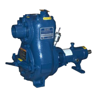
See Figure 1 for the approximate physical dimen some of the information such as mounting, line sions of this pump. OUTLINE DRAWING Figure B-1. Pump Model 12C2-B INSTALLATION PAGE B - 1... -
Page 9: Preinstallation Inspection
OM-00602 10 SERIES PREINSTALLATION INSPECTION POSITIONING PUMP The pump assembly was inspected and tested be fore shipment from the factory. Before installation, inspect the pump for damage which may have oc curred during shipment. Check as follows: Death or serious personal injury and damage to the pump or components a. -
Page 10: Suction And Discharge Piping
10 SERIES OM-00602 Installation closer to the pump may result in erratic SUCTION AND DISCHARGE PIPING readings. SUCTION LINES Pump performance is adversely effected by in creased suction lift, discharge elevation, and fric To avoid air pockets which could affect pump prim tion losses. -
Page 11: Suction Lines In Sumps
OM-00602 10 SERIES Suction Lines In Sumps of one or both pumps. To avoid this, position the suction inlets so that they are separated by a dis If a single suction line is installed in a sump, it tance equal to at least 3 times the diameter of the should be positioned away from the wall of the suction pipe. -
Page 12: Discharge Lines
10 SERIES OM-00602 In low discharge head applications (less than 30 DISCHARGE LINES feet (9,1 m)), it is recommended that the bypass line be run back to the wet well, and located 6 Siphoning inches below the water level or cut‐off point of the low level pump. -
Page 13: Automatic Air Release Valve
OM-00602 10 SERIES AUTOMATIC AIR RELEASE VALVE When properly installed, a Gorman‐Rupp Auto matic Air Release Valve will permit air to escape A manual shut‐off valve should not be through the bypass line and then close automati installed in any bypass line. A manual cally when the pump is fully primed and pumping shut‐off valve may inadvertently be left at full capacity. -
Page 14: Alignment
10 SERIES OM-00602 DISCHARGE PIPE CLEAN‐OUT COVER INSTALL AIR RELEASE VALVE IN HORIZONTAL POSITION DISCHARGE CHECK VALVE 90_ LONG RADIUS ELBOW SUPPORT PUMP DISCHARGE BRACKET SELF‐PRIMING CENTRIFUGAL PUMP BLEED LINE 1” (25,4 MM) DIA. MIN. (CUSTOMER FUR NISHED) DO NOT EX SUCTION TEND BELOW PUMP LINE... -
Page 15: Coupled Drives
OM-00602 10 SERIES when the hubs are the same distance apart at all points (see Figure 4B). Check parallel adjustment by laying a straightedge Adjusting the alignment in one direction across both coupling rims at the top, bottom, and may alter the alignment in another direc side. -
Page 16: V-Belt Tensioning
10 SERIES OM-00602 The ratio of deflection to belt span is 1:64 for both parts can catch clothing, fingers, or tools, causing severe injury to person ASA and metric units. Therefore, a belt with a span nel. of 64 inches would require a deflection of 1 inch at the force shown on the Tables for your particular V‐BELT TENSIONING application. - Page 17 OM-00602 10 SERIES Table 1. Sheave Diameter (Inches) Table 2. Sheave Diameter (Millimeters) Deflection Force (Lbs.) Deflection Force (KG.) Belt Deflection Force Belt Deflection Force Uncogged Cogged Uncogged Cogged Hy‐T Belts & Torque‐Flex Hy‐T Belts & Torque‐Flex Uncogged & Machined Uncogged &...
-
Page 18: Operation - Section C
OM-00602 10 SERIES OPERATION - SECTION C Review all SAFETY information in Section A. 1. The pump is being put into service for the first time. Follow the instructions on all tags, labels and 2. The pump has not been used for a consider decals attached to the pump. -
Page 19: Operation
OM-00602 10 SERIES Consult the operating manual furnished with the Leakage power source before attempting to start the power source. No leakage should be visible at pump mating sur faces, or at pump connections or fittings. Keep all If an electric motor is used to drive the pump, re line connections and fittings tight to maintain maxi... -
Page 20: Pump Vacuum Check
OM-00602 10 SERIES Pump Vacuum Check Temperatures up to 160_F (71_C) are considered normal for bearings, and they can operate safely to With the pump inoperative, install a vacuum gauge at least 180_F (82_C). in the system, using pipe dope on the threads. Block the suction line and start the pump. - Page 21 10 SERIES OM-00602 TROUBLESHOOTING - SECTION D Review all SAFETY information in Section A. Before attempting to open or service the pump: 1. Familiarize yourself with this manual. 2. Disconnect or lock out the power source to ensure that the pump will remain inoperative.
- Page 22 OM-00602 10 SERIES TROUBLE POSSIBLE CAUSE PROBABLE REMEDY Impeller or other wearing parts worn Replace worn or damaged parts. PUMP STOPS OR FAILS TO DELIVER or damaged. Check that impeller is properly RATED FLOW OR centered and rotates freely. PRESSURE (cont.) Impeller clogged.
- Page 23 10 SERIES OM-00602 equipped) between regularly scheduled inspec PREVENTIVE MAINTENANCE tions can indicate problems that can be corrected Since pump applications are seldom identical, and before system damage or catastrophic failure oc pump wear is directly affected by such things as curs.
- Page 24 PUMP MAINTENANCE AND REPAIR ‐ SECTION E MAINTENANCE AND REPAIR OF THE WEARING PARTS OF THE PUMP WILL MAINTAIN PEAK OPERATING PERFORMANCE. STANDARD PERFORMANCE FOR PUMP MODEL 12C2-B Based on 70_ F (21_ C) clear water at sea level Contact the Gorman‐Rupp Company to verify per...
- Page 25 OM-00602 10 SERIES PARTS PAGE SECTION DRAWING Figure E-1. Pump Model 12C2-B PAGE E - 2 MAINTENANCE & REPAIR...
- Page 26 10 SERIES OM-00602 PARTS LIST Pump Model 12C2-B (From S/N 722995 Up) If your pump serial number is followed by an “N”, your pump is NOT a standard production model. Contact the Gorman‐Rupp Company to verify part numbers. ITEM PART NAME...
- Page 27 OM-00602 10 SERIES PUMP AND SEAL DISASSEMBLY 4. Check the temperature before opening any covers, plates, or AND REASSEMBLY plugs. 5. Close the suction and discharge Review all SAFETY information Section A. valves. 6. Vent the pump slowly and cau Follow the instructions on all tags, label and de...
- Page 28 10 SERIES OM-00602 If the check valve assembly (5) is to be serviced, re the drive end of the shaft) as shown in Figure E-2. move the check valve pin (4), reach through the Use caution not to damage the shaft or keyway. back cover opening and pull the complete assem...
- Page 29 OM-00602 10 SERIES Shaft and Bearing Removal and Disassembly When the pump is properly operated and main tained, the pedestal should not require disassem To prevent damage during removal from bly. Disassemble the shaft and bearings only the shaft, it is recommended that bearings when there is evidence of wear or damage.
- Page 30 10 SERIES OM-00602 Replace the bearings, shaft, or pedestal if the If heating the bearings is not practical, use a suit proper bearing fit is not achieved. ably sized sleeve and an arbor (or hydraulic) press to install the bearings on the shaft. If bearing replacement is required, use a bearing puller to remove the inboard and outboard bear...
- Page 31 OM-00602 10 SERIES Seal Reassembly and Installation Handle the seal parts with extreme care to prevent damage. Be careful not to contaminate precision (Figures E-1 and E-3) finished faces; even fingerprints on the faces can shorten seal life. If necessary, clean the faces with a non‐oil based solvent and a clean, lint‐free tissue.
- Page 32 10 SERIES OM-00602 Impeller Installation and Adjustment Inspect the impeller and replace it if cracked or badly worn. Install the same thickness of impeller This seal is not designed for operation at shims (15) as previously removed, and screw the temperatures above 110_F (43_C).
- Page 33 OM-00602 10 SERIES leveling shims used under the mounting feet of the Secure the back cover assembly by installing the pump casing. clamp bar (45) and tightening the clamp bar screw (47). Do not over‐tighten the clamp bar screw; it Suction Check Valve Installation should be just tight enough to seal the back cover shoulder.
- Page 34 10 SERIES OM-00602 POSITION POSITION POSITION WHEN WHEN EMPTY FILLING IN USE GREASE FITTING CROSS RELIEF HOLE Figure E-4. Automatic Lubricating Grease Cup Bearings The pedestal was fully lubricated when shipped Monitor the condition of the bearing lubri from the factory. Check the oil level regularly cant regularly for evidence of rust or mois...
- Page 35 For Warranty Information, Please Visit www.grpumps.com/warranty or call: U.S.: 419-755-1280 Canada: 519-631-2870 International: +1-419-755-1352 GORMAN‐RUPP PUMPS...
Need help?
Do you have a question about the 12C2-B and is the answer not in the manual?
Questions and answers