
Subscribe to Our Youtube Channel
Related Manuals for Moxa Technologies TCC-120


Summary of Contents for Moxa Technologies TCC-120
- Page 1 Moxa TCC-120/120I Hardware Installation Guide Eleventh Edition, January 2015 www.moxa.com/product © 2015 Moxa Inc. All rights reserved. P/N: 1802001200303 www.ipc2u.ru www.moxa.pro...
- Page 2 Moxa TCC-120/120I Hardware Installation Guide The software described in this manual is furnished under a license agreement and may be used only in accordance with the terms of that agreement. Copyright Notice © 2015 Moxa Inc. All rights reserved. Trademarks The MOXA logo is a registered trademark of Moxa Inc.
-
Page 3: Technical Support Contact Information
Technical Support Contact Information www.moxa.com/support Moxa Americas Moxa China (Shanghai office) Toll-free: 1-888-669-2872 Tel: +86-21-5258-9955 Tel: +1-714-528-6777 Fax: +86-21-5258-5505 Fax: +1-714-528-6778 Moxa Europe Moxa Asia-Pacific Tel: +49-89-3700399-0 Tel: +886-2-8919-1230 Fax: +49-89-3700399-99 Fax: +886-2-8919-1231 Moxa India Tel: +91-80-4172-9088 Fax: +91-80-4132-1045 www.ipc2u.ru www.moxa.pro... -
Page 4: Table Of Contents
Table of Contents 1. Introduction ............. 1 Overview ..............2 Introduction .............. 2 Built-in RS-485 ADDC Intelligence ......3 Isolation ..............3 Reverse Power Protection ........... 3 DIP Switch Selectable Terminator ........ 3 Auto Baudrate Detection ..........3 Product Features ............4 Package Checklist ............ -
Page 5: Introduction
Introduction The TCC-120 and TCC-120I are RS-422/485 isolated repeaters, and the TCC-120I comes with 2 kV isolation protection. The following topics are covered in this chapter: Overview Introduction Built-in RS-485 ADDC Intelligence Isolation Reverse Power Protection ... -
Page 6: Overview
RS-422 or RS-485 interface for data transmission. In some cases however, it is necessary to extend the transmission distance between RS-422/485 devices. This is where the TCC-120/120I RS-422/485 repeaters come in. Simply wire the power terminal block, wire the two signal terminal blocks, set the DIP switches, and you’re ready to go. -
Page 7: Built-In Rs-485 Addc Tm Intelligence
Moxa offers a better solution. The TCC-120/120I’s terminator is set with a DIP switch located on the outside of the converter’s casing. -
Page 8: Product Features
PWR, Tx, Rx LEDs • Operating temperature from -20 to 60°C • 2 kV isolation (for the TCC-120I) Package Checklist Before installing the TCC-120/120I, verify that the package contains the following items: Standard Accessories: • TCC-120 or TCC-120I • DIN-rail mounting kit •... -
Page 9: Product Specifications
External 12-48 VDC Power, Terminal Block Reverse Power Protection Protects against V+/V- reversal Over Current Protection Protects against 2 signals shorted together Power Consumption TCC-120: TCC-120I: 65mA @ 12V 180mA @ 12V 37mA @ 24V 90mA @ 24V 26mA @ 48V 52mA @ 48V Mechanical Dimensions (W ×... -
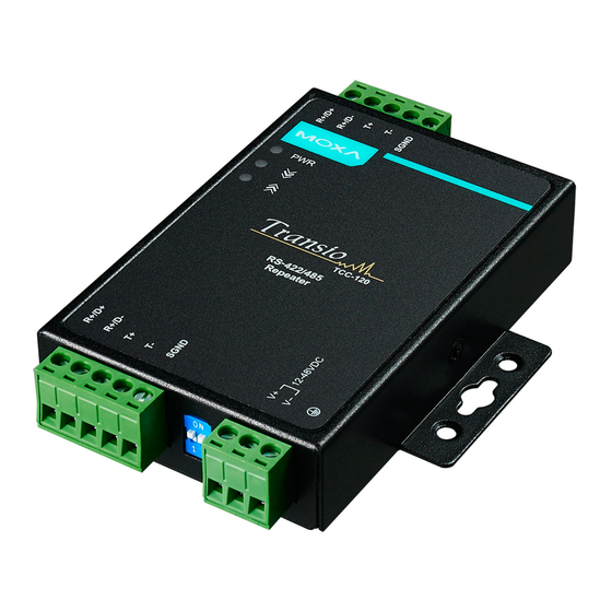
Page 10: Product Views
Product Views www.ipc2u.ru www.moxa.pro... -
Page 11: Led Indicators
LED Indicators The TCC-120/120I’s top panel contains three LED indicators, as described in the table below: LED Name LED Function Red indicates the power is on. Data is entering through the top-end port and Orange exiting through the bottom-end port. -
Page 12: Installation
Installation This chapter includes information about how to install the TCC-120/120I. Five steps are required to install the TCC-120/120I: STEP 1: Set the terminator DIP Switches • STEP 2: Attach the Power Supply • STEP 3: Wire the RS-422/485 Terminal Blocks •... -
Page 13: Step 1: Set The Dip Switches
STEP 1: Set the DIP Switches The DIP switches on the TCC-120/120I are used to set the signal transmission mode and to enable or disable the termination resistor. You can configure for either 2-wire (RS-485) or 4-wire (RS-422/485) transmission modes. Also note that your program and serial port should be set to match the repeater’s settings. - Page 14 Dip Switch Settings RS-422 Terminator active RS-422 4-wire RS-485 Terminator active 4-wire RS-485 2-wire RS-485 Terminator active 2-wire RS-485 NOTE These switch settings apply for product revision 1.3 and later; for the switch settings of previous product revisions, refer to the label on the rear panel for the correct information.
- Page 15 The newly implemented DIP-2 (S3 and S4) switches are used to configure the pull high/low resistors for different applications. Pull High/Low Resistor DIP-2 SW1 DIP-2 SW2 150k 1k (default) NOTE We recommend setting the pull high/low resistor to 1k (ON/ON) when termination is enabled.
-
Page 16: Step 2: Attach The Power Supply
NOTE The TCC-120/120I provide reverse power protection. The products will automatically detect which power wire is negative, and which is positive. STEP 3: Wire the Terminal Block There are two wiring options available for connecting to the TCC-120/120I’s RS-422/485 terminal block. 2-wire When using the 2-wire (for... -
Page 17: Step 4: Test The Connection
TCC-120/120I’s two RS-422/485 ports. STEP 5: Placement In addition to placing the TCC-120/120I on a desktop or other horizontal surface, you may also make use of the DIN-rail or wall mount options, as illustrated here. - Page 18 www.ipc2u.ru www.moxa.pro...
Need help?
Do you have a question about the TCC-120 and is the answer not in the manual?
Questions and answers