Table of Contents
Advertisement
Quick Links
Advertisement
Table of Contents

Related Manuals for CYP PU-HBTL-EX


Summary of Contents for CYP PU-HBTL-EX
- Page 1 PU-HBTL-EX 60m HDBaseT™ LITE Repeater Operation Manual Operation Manual...
-
Page 3: Safety Precautions
SAFETY PRECAUTIONS Please read all instructions before attempting to unpack, install or operate this equipment and before connecting the power supply. Please keep the following in mind as you unpack and install this equipment: • Always follow basic safety precautions to reduce the risk of fire, electrical shock and injury to persons. -
Page 4: Table Of Contents
CONTENTS 1. Introduction ..........1 2. Applications ........... 1 3. Package Contents ........ 1 4. System Requirements ......1 5. Features ..........2 6. Operation Controls and Functions ..3 6.1 Front Panel .........3 6.2 Rear Panel .........4 7. Connection Diagram ......5 8. -
Page 5: Introduction
1. INTRODUCTION This HDBaseT™ Repeater allows HDBaseT Lite systems to be extended and cascaded. Supporting the highest quality of uncompressed high-definition HD video up to 4K×2K (Ultra HD), up to 8 channels of uncompressed multi-channel audio, RS-233 and IR control systems, complete HDBaseT 3 Play™... -
Page 6: Features
5. FEATURES • HDCP and DVI Compliant • Supports 3D over HDMI and 4k×2k (Ultra HD) resolution • Supports CEC bypass • Supports the extension of the transmission range of uncompressed data up to 60m (1080p) with a single repeater, up to 120m (1080p) with optional second repeater unit and up to 180m with optional third Repeater unit. -
Page 7: Operation Controls And Functions
6. OPERATION CONTROLS AND FUNCTIONS 6.1 Front Panel HDBaseT Repeater MODE LINK CAT5e/6 OUT MODE LED: The yellow LED will flash when the unit is powered or when an active receiver is connected. CAT5e/6/7 OUT: Connect to the receiver unit with a single CAT5e/6/7 cable (up to 60m). -
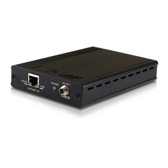
Page 8: Rear Panel
6.2 Rear Panel DC 24V POWER MODE LINK CAT5e/6 IN MODE LED: The yellow LED will flash when the unit is powered or when an active transmitter is connected. CAT5e/6/7 IN: Connect to the transmitter unit with a single CAT5e/6/7 cable (up to 60m). LINK LED: The green LED will illuminate when output is connected to an active receiver. -
Page 9: Connection Diagram
7. CONNECTION DIAGRAM Example 1 RS-232 Blu-ray Player Equipped PC or Control System 1.5m HDMI 60° 60° Input IR Extender IR Blaster RS-232 IR2 Extender HDMI In TXPL RS232 In IR1 Blaster Power DC 24V Supply Power Link Lite CAT 5e /6 Out Power 60 m Supply... - Page 10 Example 2 Blu-ray Player 1.5m HDMI 60° RS-232 60° Input IR Blaster Power IR Extender Supply Power Supply 60 m Front DC 24V POWER MODE LINK CAT5e/6 IN Rear HDBaseT Repeater MODE LINK CAT5e/6 OUT Power Supply 60 m Optional 2nd Front DC 24V POWER...
-
Page 11: Specifications
8. SPECIFICATIONS Video Bandwidth 300 MHz/10.2 Gbps Input Port 1×RJ-45 Output Port 1×RJ-45 Resolution Support 480i~1080p@50/60, 1080p@24, 4k×2K CAT5e/6 In/Out Distance Up to 60/60 meters Power Supply 24 V/1.25 A DC (US/EU Standards, CE/ FCC/UL certified) Dimensions 102 mm (W)×145 mm (D)×25 mm (H) Weight 324 g Chassis Material... -
Page 12: Acronyms
9. ACRONYMS ACRONYM COMPLETE TERM CAT5e Category 5 Cable CAT6 Category 6 Cable CAT7 Category 7 Cable Consumer Electronics Control HDCP High-bandwidth Digital Content Protection HDMI High Definition Multimedia Interface Power over Ethernet... - Page 13 www.cypeurope.com...
Need help?
Do you have a question about the PU-HBTL-EX and is the answer not in the manual?
Questions and answers