Mitsubishi Electric Mr.Slim PUH-P25VGAA Service Manual
Split-type, heat pump air conditioners, r407c, outdoor unit
Hide thumbs
Also See for Mr.Slim PUH-P25VGAA:
- Technical data book (106 pages) ,
- Technical & service manual (90 pages) ,
- Operation manual (88 pages)
Table of Contents
Advertisement
SPLIT-TYPE, HEAT PUMP AIR CONDITIONERS
SPLIT-TYPE, AIR CONDITIONERS
SERVICE MANUAL
R407C
[model names]
PUH-P25VGAA
PUH-P35VGAA
PU-P35VGAA
PUH-P35YGAA
PU-P35YGAA
PUH-P50VGAA
PU-P50VGAA
PUH-P50YGAA
PU-P50YGAA
PUH-P60VGAA
PU-P60VGAA
PUH-P60YGAA
PU-P60YGAA
PUH-P71VGAA
PU-P71VGAA
PUH-P71YGAA
PU-P71YGAA
PUH-P100VGAA PU-P100VGAA
PUH-P100YGAA PU-P100YGAA
PUH-P125YGAA PU-P125YGAA
PUH-P140YGAA PU-P140YGAA
[Service Ref.]
Service Ref. is on page 2.
• This manual describes only
service data of the outdoor
units.
CONTENTS
1. REFERENCE MANUAL··································3
2. SAFETY PRECAUTION··································4
3. PART NAMES AND FUNCTIONS ··················6
4. SPECIFICATIONS···········································7
5. DATA ·····························································11
6. OUTLINES AND DIMENSIONS ····················18
7. WIRING DIAGRAM ·······································22
8. WIRING SPECIFICATIONS ··························24
9. REFRIGERANT SYSTEM DIAGRAM··············28
10. TROUBLESHOOTING ··································30
11. FUNCTION SETTING ···································65
12. DISASSEMBLY PROCEDURE ·····················71
13. PARTS LIST ··················································75
August 2005
No.OC336
Advertisement
Table of Contents
Troubleshooting

Related Manuals for Mitsubishi Electric Mr.Slim PUH-P25VGAA


Summary of Contents for Mitsubishi Electric Mr.Slim PUH-P25VGAA
-
Page 1: Service Manual
SPLIT-TYPE, HEAT PUMP AIR CONDITIONERS SPLIT-TYPE, AIR CONDITIONERS August 2005 No.OC336 SERVICE MANUAL R407C Outdoor unit [model names] [Service Ref.] Service Ref. is on page 2. • This manual describes only PUH-P25VGAA service data of the outdoor PUH-P35VGAA PU-P35VGAA units. PUH-P35YGAA PU-P35YGAA PUH-P50VGAA... - Page 2 [Service Ref.] PUH-P25VGAA.UK PUH-P35VGAA.UK PU-P35VGAA.UK PUH-P35YGAA.UK PU-P35YGAA.UK PUH-P50VGAA.UK PU-P50VGAA.UK PUH-P50YGAA.UK PU-P50YGAA.UK PUH-P60VGAA.UK PU-P60VGAA.UK PUH-P60YGAA.UK PU-P60YGAA.UK PUH-P71VGAA.UK PU-P71VGAA.UK PUH-P71YGAA.UK PU-P71YGAA.UK PUH-P100VGAA.UK PU-P100VGAA.UK PUH-P100YGAA.UK PU-P100YGAA.UK PUH-P125YGAA.UK PU-P125YGAA.UK PUH-P140YGAA.UK PU-P140YGAA.UK...
-
Page 3: Reference Manual
REFERENCE MANUAL 1-1. INDOOR UNIT'S SERVICE MANUAL Model name Service Ref. Service Manual No. PLA-RP35/50/60/71AA PLA-RP35/50/60/71AA.UK OC335 PLA-RP100/125/140AA PLA-RP100/125/140AA.UK PLH-P35/50/60/71AAH PLH-P35/50/60/71AAH.UK PLH-P100/125/140AAH PLH-P100/125/140AAH.UK PMH-P25/35/50BA PMH-P25/35/50BA OC333 PCA-RP50/60/71/100/125/140GA PCA-RP50/60/71/100/125/140GA OC328 PCH-P50/60/71/100/125/140GAH PCH-P50/60/71/100/125/140GAH PCA-RP71/125HA PCA-RP71/125HA OC329 PKA-RP35/50GAL PKA-RP35/50GAL OC330 PKH-P35/50GALH PKH-P35/50GALH PKA-RP60/71/100FAL PKA-RP60/71/100FAL OC331 PKH-P60/71/100FALH... -
Page 4: Safety Precaution
SAFETY PRECAUTION CAUTIONS RELATED TO NEW REFRIGERANT Cautions for units utilising refrigerant R407C Do not use the existing refrigerant piping. Use liquid refrigerant to charge the system. The old refrigerant and lubricant in the existing piping If gas refrigerant is used to seal the system, the composition contains a large amount of chlorine which may cause the of the refrigerant in the cylinder will change and performance lubricant deterioration of the new unit. - Page 5 [3] Service tools Use the below service tools as exclusive tools for R407C refrigerant. Tool name Specifications Gauge manifold ·Only for R407C. ·Use the existing fitting SPECIFICATIONS. (UNF7/16) ·Use high-tension side pressure of 3.43MPa·G or over. Charge hose ·Only for R407C. ·Use pressure performance of 5.10MPa·G or over.
-
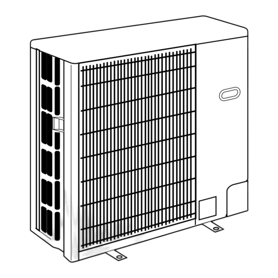
Page 6: Part Names And Functions
PART NAMES AND FUNCTIONS Air outlet (Expels warm air during cooling) Air outlet Air intake Air intake PUH-P25VGAA.UK PUH-P50VGAA.UK PUH-P50YGAA.UK PUH-P35VGAA.UK PUH-P60VGAA.UK PUH-P60YGAA.UK PUH-P35YGAA.UK PUH-P71VGAA.UK PUH-P71YGAA.UK PU-P35VGAA.UK PU-P50VGAA.UK PU-P50YGAA.UK PU-P35YGAA.UK PU-P60VGAA.UK PU-P60YGAA.UK PU-P71VGAA.UK PU-P71YGAA.UK Air outlet Air outlet Air intake Air intake PUH-P100VGAA.UK PUH-P125YGAA.UK... -
Page 7: Specifications
SPECIFICATIONS 4-1. HEAT PUMP PUH-P25VAA.UK PUH-P35VGAA / YGAA.UK Service Ref. Cooling Heating Cooling Heating Mode Single,50Hz,230V Single,50Hz,230V / 3-ph,50Hz,400V Power supply (phase, cycle, voltage) Running current 5.32 4.89 7.61 / 2.54 7.85 / 2.62 7.23 10.67/5.4 Max current External finish Munsell 5Y 7/1 Refrigerant control Linear Expansion Valve... - Page 8 PUH-P100VGAA / YGAA.UK PUH-P71VGAA / YGAA.UK Service Ref. Mode Cooling Heating Cooling Heating Single, 50Hz, 230V / 3-ph, 50Hz, 400V(4wires) Power supply (phase, cycle, voltage) Running current 15.66 / 5.23 16.67 / 5.56 16.43/ 5.48 17.34 / 5.79 22.66 / 10.8 23.57 / 10.8 Max current External finish...
- Page 9 4-2. COOLING ONLY TYPE PU-P35VGAA / YGAA.UK PU-P50VGAA / YGAA.UK PU-P60VGAA / YGAA.UK Service Ref. Cooling Cooling Cooling Mode Single, 50Hz, 230V / 3-ph, 50Hz, 400V(4wires) Power supply (phase, cycle, voltage) Running current 7.61 / 2.54 10.97 / 3.98 13.27 / 4.43 10.67 / 5.4 15.35 / 7.0 18.03 / 7.7...
- Page 10 PU-P125YGAA.UK PU-P140YGAA.UK Service Ref. Mode Cooling Cooling 3-ph, 50Hz,400V(4wires) Power supply (phase, cycle, voltage) Running current 7.52 8.92 18.0 20.4 Max. current External finish Munsell 5Y 7/1 Linear Expansion Valve Refrigerant control Hermetic Compressor BE82YADMT BE96YADMT Model Motor output Line start Starter type Thermal relay, HP switch, Discharge thermo Protection devices...
- Page 11 DATA 5-1. REFILLING REFRIGERANT CHARGE (R407C : kg) Piping length (one way) Factory Service Ref. charged PUH-P25VGAA.UK — — PUH-P35VGAA.UK — PU-P35VGAA.UK PUH-P35YGAA.UK — PU-P35YGAA.UK PUH-P50VGAA.UK — PU-P50VGAA.UK PUH-P50YGAA.UK — PU-P50YGAA.UK PUH-P60VGAA.UK PU-P60VGAA.UK PUH-P60YGAA.UK PU-P60YGAA.UK PUH-P71VGAA.UK PU-P71VGAA.UK PUH-P71YGAA.UK PU-P71YGAA.UK PUH-P100VGAA.UK PU-P100VGAA.UK PUH-P100YGAA.UK PU-P100YGAA.UK...
-
Page 12: Noise Criterion Curves
5-3. NOISE CRITERION CURVES MICROPHONE UNIT GROUND PUH-P25VGAA.UK PUH-P35VGAA.UK MODE SPL(dB) LINE SPL(dB) LINE MODE COOLING PUH-P35YGAA.UK COOLING HEATING HEATING PU-P35VGAA.UK PU-P35YGAA.UK NC-70 NC-70 NC-60 NC-60 NC-50 NC-50 NC-40 NC-40 NC-30 NC-30 APPROXIMATE APPROXIMATE THRESHOLD OF THRESHOLD OF HEARING FOR HEARING FOR NC-20 NC-20... - Page 13 PUH-P100VGAA.UK PUH-P71VGAA.UK SPL(dB) MODE LINE SPL(dB) LINE MODE PUH-P100YGAA.UK COOLING PUH-P71YGAA.UK COOLING HEATING PU-P100VGAA.UK HEATING PU-P71VGAA.UK PU-P100YGAA.UK PU-P71YGAA.UK NC-70 NC-70 NC-60 NC-60 NC-50 NC-50 NC-40 NC-40 NC-30 NC-30 APPROXIMATE APPROXIMATE THRESHOLD OF THRESHOLD OF HEARING FOR HEARING FOR NC-20 NC-20 CONTINUOUS CONTINUOUS NOISE...
-
Page 14: Standard Operation Data
5-4. STANDARD OPERATION DATA Heat pump type Representative matching PMH-P25BA PLA-RP35AA PLA-RP50AA PLA-RP60AA Mode Cooling Heating Cooling Heating Cooling Heating Cooling Heating Capacity 4,500 4,950 5,600 6,350 6,700 7,300 3,100 3,350 Input 1.72 1.70 2.53 2.20 2.57 2.40 1.14 1.05 Indoor unit PMH-P25BA PLA-RP35AA... - Page 15 Representative matching PLA-RP71AA PLA-RP100AA PLA-RP125AA PLA-RP140AA Mode Cooling Heating Cooling Heating Cooling Heating Cooling Heating Capacity 7,700 9,200 9,600 10,500 13,300 15,600 14,200 17,000 Input 3.42 3.48 3.68 3.91 5.09 5.54 5.90 6.35 Indoor unit PLA-RP71AA PLA-RP100AA PLA-RP125AA PLA-RP140AA Phase , Hz 1 , 50 1 , 50 1 , 50...
- Page 16 Cooling only type PLA-RP35AA PLA-RP50AA Representative matching PLA-RP60AA Mode Cooling Cooling Cooling Capacity 4,500 5,600 6,700 Input 1.72 2.53 2.57 PLA-RP35AA PLA-RP50AA PLA-RP60AA Indoor unit Phase , Hz 1 , 50 1 , 50 1 , 50 Volts Amperes 0.79 0.79 0.79 PU-P60VGAA.UK...
- Page 17 Representative matching PLA-RP71AA PLA-RP100AA PLA-RP140AA PLA-RP125AA Mode Cooling Cooling Cooling Cooling Capacity 7,700 9,200 13,300 14,200 Input 3.42 3.68 5.09 5.90 Indoor unit PLA-RP71AA PLA-RP100AA PLA-RP140AA PLA-RP125AA 1 , 50 Phase , Hz 1 , 50 1 , 50 1 , 50 Volts Amperes 0.79...
-
Page 18: Outlines And Dimensions
OUTLINES AND DIMENSIONS OUTDOOR UNIT Unit : mm PUH-P25VGAA.UK PUH-P35VGAA.UK PUH-P35YGAA.UK PU-P35VGAA.UK PU-P35YGAA.UK... - Page 19 PUH-P50VGAA.UK Unit : mm PUH-P50YGAA.UK PUH-P60VGAA.UK PUH-P60YGAA.UK PUH-P71VGAA.UK PUH-P71YGAA.UK PU-P50VGAA.UK PU-P50YGAA.UK PU-P60VGAA.UK PU-P60YGAA.UK PU-P71VGAA.UK PU-P71YGAA.UK...
- Page 20 PUH-P100VGAA.UK Unit : mm PUH-P100YGAA.UK PU-P100VGAA.UK PU-P100YGAA.UK...
- Page 21 PUH-P125YGAA.UK Unit : mm PUH-P140YGAA.UK PU-P125YGAA.UK PU-P140YGAA.UK...
-
Page 22: Wiring Diagram
WIRING DIAGRAM PUH-P25VGAA.UK PUH-P35VGAA.UK PUH-P50VGAA.UK PUH-P60VGAA.UK PUH-P71VGAA.UK PUH-P100VGAA.UK PU-P35VGAA.UK PU-P50VGAA.UK PU-P60VGAA.UK PU-P71VGAA.UK PU-P100VGAA.UK SYMBOL NAME SYMBOL NAME COMPRESSOR (INNER THERMOSTAT) OUTDOOR CONTROLLER BOARD FAN MOTOR (INNER THERMOSTAT) FUSE1 (O.B) FUSE (6.3A) THERMISTOR LIQUID TEMP FUSE2 (O.B) FUSE (6.3A) DISCHARGE TEMP FUSE3 (O.B) FUSE (6.3A) COND. - Page 23 PUH-P35YGAA.UK PUH-P50YGAA.UK PUH-P60YGAA.UK PUH-P71YGAA.UK PUH-P100YGAA.UK PUH-P125YGAA.UK PUH-P140YGAA.UK PU-P35YGAA.UK PU-P50YGAA.UK PU-P60YGAA-UK PU-P71YGAA.UK PU-P100YGAA.UK PU-P125YGAA.UK PU-P140YGAA.UK SYMBOL NAME SYMBOL NAME COMPRESSOR OUTDOOR CONTROLLER BOARD FAN MOTOR (INNER THERMOSTAT) FUSE1 (O.B) FUSE (6.3A) THERMISTOR LIQUID TEMP FUSE2 (O.B) FUSE (6.3A) DISCHARGE TEMP FUSE3 (O.B) FUSE (6.3A) COND.
-
Page 24: Wiring Specifications
WIRING SPECIFICATIONS 8-1. FIELD ELECTRICAL WIRING (power wiring specifications) Outdoor unit model P25,35V P50,60V P71,100V P35,50,60,71,100Y P125, 140Y Outdoor unit power supply ~/N (single), 50 Hz, ~/N (single), 50 Hz, ~/N (single), 50 Hz, 3N ~ (3phase), 50 Hz, 3N ~ (3phase), 50 Hz, 230 V 230 V 230 V... - Page 25 8-2. INDOOR-OUTDOOR CONNECTING CABLE L(m) Wire size Number Cross section Polarity of cable of wires Round Clockwise : S1-S2-S3 (50) w Pay attention to stripe of yellow and green Flat Not applicable applicable (Because center wire has no cover finish) Flat (45) From left to right : S1-Open-S2-S3...
- Page 26 8-3. M-NET WIRING METHOD (Points to notice) (1) Outside the unit, transmission wires should stay away from electric wires in order to prevent electromagnetic noise from making an influence on the signal communication. Place them at intervals of more than 5cm. Do not put them in the same conduit tube.
- Page 27 M-NET wiring M-NET (1) Use 2-core x 1.25mm shield wire for electric wires. terminal Ground (Excluding the case connecting to system controller.) block wire (2) Connect the wire to the M-NET terminal block.Connect one core of the transmission wire (non-polar) to A terminal and the other to B. Peel the shield wire, twist the shield part to a string and connect it to S terminal.
-
Page 28: Refrigerant System Diagram
REFRIGERANT SYSTEM DIAGRAM PUH-P25VGAA.UK PUH-P35VGAA.UK PUH-P50VGAA.UK PUH-P60VGAA.UK PUH-P71VGAA.UK PUH-P35YGAA.UK PUH-P50YGAA.UK PUH-P60YGAA.UK PUH-P71YGAA.UK <4-way valve solenoid coil> Heating : ON High pressure Ball valve Cooling : OFF 4-way valve protect switch Outdoor heat exchanger (#50) Refrigerant GAS pipe Strainer Thermistor P25···12.7A({1/2") (TH6) P35~P71···15.88A({5/8") Service... - Page 29 PU-P35VGAA.UK PU-P50VGAA.UK PU-P60VGAA.UK PU-P71VGAA.UK PU-P35YGAA.UK PU-P50YGAA.UK PU-P60YGAA.UK PU-P71YGAA.UK High pressure Ball valve protect switch Outdoor heat exchanger (#50) Strainer Thermistor Refrigerant GAS pipe (TH6) 15.88A({5/8") Service Thermistor Service port (TH3) port Thermistor(TH4) Distributor Accumulator with strainer Compressor (#100) (#100) Strainer Strainer Refrigerant LIQUID pipe 9.52A({3/8")
-
Page 30: Troubleshooting
TROUBLESHOOTING 10-1. TROUBLESHOOTING <Error code display by self-diagnosis and actions to be taken for service (summary)> Present and past error codes are logged and displayed on the wired remote controller and control board of outdoor unit. Actions to be taken for service, which depends on whether or not the inferior phenomenon is reoccurring at service, are sum- marized in the table below. - Page 31 Operating procedures While the room temperature display on the remote "TEST RUN" and the currently selected controller is “PLEASE WAIT”, the remote controller is disabled. operation mode are displayed altemately. Wait until “PLEASE WAIT” disappears before using remote controller. 1. Turn on the main power supply. “PLEASE WAIT”...
- Page 32 Test run [for wireless remote controller] Measure an impedance between the power supply terminal block on the outdoor unit and ground with a 500V Megger and check that it is equal to or greater than 1.0M". TEST RUN 1 Turn on the main power to the unit. TEST RUN 2 Press the button twice continuously.
- Page 33 10-3. HOW TO PRECEED "SELF-DIAGNOSIS" 10-3-1. When a Problem Occurs During Operation If a problem occurs in the air conditioner, the indoor and outdoor units will stop, and the problem is shown in the remote controller display. [CHECK] and the refrigerant address are displayed on the temperature display, and the error code and unit number are displayed alternately as shown below.
-
Page 34: Remote Controller Diagnosis
When the error history is reset, the display will look like the one shown below. Press the button twice within three seconds. The self-diagnosis ON/OFF However, if you fail to reset the error history, the error content will be displayed again. address or refrigerant address will flash. - Page 35 10-3-4. Malfunction-diagnosis method by wireless remote controller <In case of trouble during operation> When a malfunction occurs to air conditioner, both indoor unit and outdoor unit will stop and operation lamp blinks to inform unusual stop. < Malfunction-diagnosis method at maintenance service> [Procedure] 1.
- Page 36 • Refer to the following tables for details on the check codes. [Output pattern A] Beeper sounds Beep Beep Beep Beep Beep Beep Beep OPERATION · · · Repeated INDICATOR lamp flash pattern Approx. 2.5 sec. 0.5 sec. 0.5 sec. 0.5 sec.
-
Page 37: Self-Diagnosis Action Table
10-4. SELF-DIAGNOSIS ACTION TABLE <Abnormalities detected when the power is put on> (Note 1) The number in ( ) is the error cord of upper remote controller (M-NET) Error Code Meaning of error code and detection method Case Judgment and action 1 No voltage is supplied to termi- 1 Check following items. - Page 38 Case Error Code Meaning of error code and detection method Judgment and action 1 Check disconnection or looseness or polarity Indoor/outdoor unit connector mis- 1 Contact failure or mis-wiring of wiring, excessive number of units (5 indoor/outdoor unit connecting of indoor/outdoor unit connecting wire of units or more) indoor and outdoor units.
- Page 39 Case Error Code Meaning of error code and detection method Judgment and action 1 Short cycle of indoor unit 1-6 Check indoor unit and repair defectives. Abnormal high pressure (High-pressure switch 63H worked) 2 Clogged filter of indoor unit 7 Check full open stop valve. Abnormal if high-pressure switch 63H 3 Decreased airflow caused by 8 Check piping and repair defectives.
- Page 40 Case Error Code Meaning of error code and detection method Judgment and action Abnormal shortage of refrigerant 1 Leakage or shortage of refrig- 1 Check leakage of refrigerant. Abnormal if intake super heat exceeds fol- erant Charge refrigerant. lowing temperature during heating com- 2 Defective operation of stop 2 Check if stop valve is full open.
- Page 41 Note: E1, E2 and E4 to E7, refer to indoor unit service manual. Case Error Code Meaning of error code and detection method Judgment and action 1 Abnormal compressor 1 Check compressor. Compressor over current (start-up locked) breaking 2 Clogged indoor filter Refer to 5-2.
- Page 42 Case Error Code Meaning of error code and detection method Judgment and action 12 Put the power off, and on again to check. 1 Noise has entered transmis- Not defined error code Replace indoor controller board or outdoor This code is displayed when not defined sion wire of remote controller.
- Page 43 Error Code Meaning of error code and detection method Case Judgment and action NO ACK Common factor that has no rela- Always try the followings when the error tion with abnormality source. 1. Transmitting side controller detects “A7” occures. 1 The unit of former address abnormal if a massage was transmitted does not exist as address but there is no reply (ACK) that a mas-...
- Page 44 From the previous page. Error Code Meaning of error code and detection method Case Judgment and action Same as mentioned in “A7” of the previous 5. If displayed address or attribute is 1 During sequential operation of page. FRESH MASTER, indoor unit and FRESH MAS- TER of other refrigerant sys- Indoor unit detects abnormality when...
-
Page 45: Troubleshooting By Inferior Phenomena
10-5. TROUBLESHOOTING BY INFERIOR PHENOMENA Phenomena Factor Countermeasure (1)Remote controller display does not Reference (Meaning of the indoor control board LED) work. (Electric current marker “ ” is not LED1 : Micro computer power supply displayed on the remote controller.) ..Display of DC14V is supply or not from indoor power. - Page 46 Phenomena Factor Countermeasure 1Louver motor fault. 1Louver motor resistance value check (7)Left/right louver performance fault. 2Disconnecting, breaking and contact fault of the con- 2Check the removing of indoor controller nector. board (CNL) breaking line and contact fault. 1Open the grille to check the filter. (8)Though the remote controller dis- 1Filter clogging (dirt) Clean the filter and remove dust or dirt...
- Page 47 [for wired remote controller] Before you call out a repair man, check the following table to see whether there is a simple solution to your problem. Solution Problem Solution Problem The room neither gets cool nor Clean the filter. (Dust and rebris This sound is made when internal A ticking noise is heard from warm very much.
- Page 48 Solution Problem Solution Problem The unit started even though the Is this timer on? "DEFROST" is displayed (no air Frost adheres to the outdoor unit start/stop button was not pushed. Press the start/stop button to stop comes out the unit). when the outside air temperature the unit.
- Page 49 [for wireless remote controller] Before you call out a repair man, check the following table to see whether there is a simple solution to your problem. Display reading Cause Solution Problem When POWER ON/OFF button is Main power switch is turned off. Turn main power on.
- Page 50 10-6. HOW TO CHECK THE PARTS PUH-P25, P35, P50, P60, P71, P100VGAA.UK PUH-P35, P50, P60, P71, P100, P125, P140YGAA.UK PU-P35, P50, P60, P71, P100VGAA.UK PU-P35, P50, P60, P71, P100, P125, P140YGAA.UK Parts name Check points Liquid temperature Disconnect the connector then measure the resistance using a tester. (Surrounding temperature 10:~30:) thermistor (TH3) Normal...
-
Page 51: Linear Expansion Valve
<Thermistor characteristic graph> < Thermistor for lower temperature > Liquid temperature thermistor(TH3) Thermistor for Condenser/evaporator temperature lower temperature thermistor(TH6) Thermistor R =15k' ± 3% Fixed number of B=3480 ± 2% Rt=15exp { 3480( 273+t 15k' 9.6k' 6.3k' 5.2k' 4.3k' 3.0k' -20 -10 10 20 30 40 50 Temperature (:) - Page 52 <Output pulse signal and the valve operation> Output Output (Phase) Closing a valve : 1 Opening a valve : 4 The output pulse shifts in above order. 1. When linear expansion valve operation stops, all output phase become OFF. 2. At phase interruption or when phase does not shift in order, motor does not rotate smoothly and motor will locks and vibrates.
- Page 53 10-7. TEST POINT DIAGRAM Outdoor controller board PUH-P25, P35, P50, P60, P71, P100VGAA.UK PUH-P35, P50, P60, P71, P100, P125, P140YGAA.UK PU-P35, P50, P60, P71, P100VGAA.UK PU-P35, P50, P60, P71, P100, P125, P140YGAA.UK When connecting A-control Service Tool [ PAC-SK52ST ], MF4, MF3 operation mode can be displayed (MF4 is only for PUH-P100V, PU-P100V, PUH-P100~140Y and PU-P100~140Y)
-
Page 54: Emergency Operation
10-8. EMERGENCY OPERATION 1. When the outdoor unit becomes under mentioned inspection display. Also when the wired remote controller or micro com- puter in the indoor unit is broken. If there is not any wrong section, short-circuited connector (CN31) in the outdoor con- troller board is possible to emergency operation. - Page 55 10-9. FUNCTION OF SWITCHS, CONNECTORS AND JUMPERS Outdoor switch for a new freon function table Switch Action by the switch operation Function Effective timing Signal Compulsory defrosting w1 Start Normal Heat compressor operating Abnormal history clear Clear Normal off or operating 1 2 3 4 5 6 1 2 3 4 5 6...
- Page 56 Jumper connector function table Switch Action by the switch operation Function Effective timing Signal Switch of single phase and 3 phase Single phase When power supply ON 3 phase power supply Switch of cooling When power supply ON Cooling only Cooling and heat pump only/cooling and heat pump :Short...
- Page 57 Outdoor unit operation monitor function Operation indicator SW2 : Indicator change of self diagnosis SW2 setting Display detail Explanation for display Unit Code indication 2 3 4 5 6 <Digital indicator LED1 working details> · Lighting (Normal operation) : Indicating the operation mode. (Be sure the 1 to 6 in the SW2 are set to OFF) (Initial setting) (1) Display when the power supply ON.
- Page 58 SW2 setting Display detail Explanation for display Unit Piping temperature. (TH3) – 40~90 – 40~90 (When the coil thermistor is 0:or below, “–” and temperature displays by turns.) (Example) When -10: One second interval 2 3 4 5 6 – Discharge temperature.
- Page 59 SW2 setting Display detail Explanation for display Unit Piping temperature (TH3) on error – 40~90 occurring (When the coil thermistor is 0:and less, “–” and – 40~90 temperature are displayed by turns) (Example) When –15: One second interval 2 3 4 5 6 –...
- Page 60 SW2 setting Display detail Explanation for display Unit Display as an outdoor Capacity setting display Capacity Code capacity code Code display 2 3 4 5 6 P100 P125 P140 Outdoor unit setting advice The tens digit (Total display for applied setting) Setting details Display details H·P / Cooling only...
- Page 61 SW2 setting Display detail Explanation for display Unit Indoor setting temperature 17~30 17~30 2 3 4 5 6 Outdoor piping temperature/Cond./Eva. – 39~88 (TH6) (When the temperature is 0: or less, “–” and – 39~88 temperature are displayed by turns) 2 3 4 5 6 Discharge super heat.
- Page 62 SW2 setting Display detail Explanation for display Unit 0~999 Thermo-on time to error stop. (When the time is 100 or more, the hundreds 0~999 digit and tens, units digit are displayed by turns.) Minute (Example) When 415 minutes 2 3 4 5 6 One second interval –39~88 Indoor unit piping temperature / cond.
- Page 63 <Display function of inspection for outdoor unit> • The blinking patterns of two LEDs—LED1(Green) and LED2(Red)—show the diagnoses of troubles in case of malfunction. • By 7SEG indicator board indicates the operation mode and inspection types. LED1 (Green) LED2 (Red) Indication (O.B) Error Name Inspection method...
- Page 64 From the preceding page. Indication (O.B) Error Name Inspection method LED1 LED2 (Green) (Red) 1 Check if ball valves are open. •Abnormal high discharge temperature(TH4) 3 blinks 1 blink 2 Check the continuity of connector (TH4) on outdoor controller board by using a tester. 3 Check if the unit fills the refrigerant at the same amount as specified.
-
Page 65: Function Setting
FUNCTION SETTING 11-1. UNIT FUNCTION SETTING BY THE REMOTE CONTROLLER Each function can be set according to necessity using the remote controller. The setting of function for each unit can only be done by the remote controller. Select function available from the table 1. <Table 1>... - Page 66 11-1-1. Selecting functions using the wired remote controller First, try to familiarize yourself with the flow of the function selection procedure. In this section, an example of setting the room temperature detection position is given. For actual operations, refer to steps 1 to 0 . Setting number Refrigerant address Unit number...
- Page 67 [Operating Procedure] 1 Check the setting items provided by function selection. If settings for a mode are changed by function selection, the functions of that mode will be changed accordingly. Check all the current settings according to steps 2 to 7 , fill in the "Check" column in Table 1, and then change them as necessary. For factory settings, refer to the indoor unit's installation manual. 2 Switch off the remote controller.
- Page 68 11-1-2. Selecting functions using the wireless remote controller (Type C) Functions can be selected with the wireless remote controller. Function selection using wireless remote controller is available only for refriger- ant system with wireless function. Refrigerant address cannot be specified by the wireless remote controller. [Flow of function selection procedure] The flow of the function selection procedure is shown below.
- Page 69 11-2. FUNCTION SELECTION OF REMOTE CONTROLLER The setting of the following remote controller functions can be changed using the remote controller function selection mode. Change the setting when needed. Item 1 Item 2 Item 3 (Setting content) 1.Change Language Language setting to display •...
- Page 70 Flowchart of Function Setting Setting language (English) Normal display (Display when the air condition is not running) Hold down the button and press the button for 2 seconds. Hold down the button and press the button for 2 seconds. Press the operation mode button. Press the TIMER MENU button.
-
Page 71: Disassembly Procedure
DISASSEMBLY PROCEDURE PUH-P125YGAA.UK PUH-P140YGAA.UK OPERATING PROCEDURE PHOTOS 1. Removing the Service panel and Top panel Photo 1 Top panel screws Top panel (1) Remove the 3 service panel fixing screws (5 15) and slide the hook to remove the service panel. (2) Remove the screws (3 for front, 2 for rear/5 15) of the top panel and remove it. - Page 72 OPERATING PROCEDURE PHOTOS 4. Removing the liquid temperature thermistor, discharge Photo 4 temperature thermistor and condenser/evaporator temperature thermistor Condenser/evaporator Clamp (1) Remove the service panel. (See Photo 1) temperature thermistor (2) Remove the top panel. (See Photo 1) (When the top panel removing is not possible, remove the electric parts box.
- Page 73 OPERATING PROCEDURE PHOTOS 9. Removing the high pressure switch Photo 6 (1) Remove the service panel. (See Photo 1) Lead wire (2) Remove the top panel. (See Photo 1) (3) Remove the electrical box. (See Photo 3) (4) Disconnect the lead wire of the pressure switch. (See Photo 6) Capillary (5) Remove the braze part of the pressure switch.
- Page 74 OPERATING PROCEDURE PHOTOS 12. Removing the Bell mouth Photo 9 Bell mouth fixing screw (1) Remove the 6 fan guard fixing screws (5 15) to remove it. (See Photo 1) (2) Remove the top panel. (3) Remove a bell mouth fixing screw (5 15) to remove it.
-
Page 75: Parts List
PARTS LIST STRUCTURAL PARTS PUH-P25VGAA.UK PUH-P35VGAA.UK PUH-P35YGAA.UK PU-P35VGAA.UK PU-P35YGAA.UK ty/set Price Wiring Recom- PUH-P• PU-P• Remarks Part No. Part Name Specification mended Diagram GAA.UK GAA.UK (Drawing No.) Symbol Unit Amount 25.35V 35Y 35V 35Y S70 30L 641 TOP PANEL (5 15) S71 000 051 F.ST SCREW S70 30L 613... - Page 76 STRUCTURAL PARTS PUH-P50VGAA.UK PUH-P60VGAA.UK PUH-P50YGAA.UK PUH-P60YGAA.UK PU-P50VGAA.UK PU-P60VGAA.UK PU-P50YGAA.UK PU-P60YGAA.UK 9 10 11 12 ty/set Price Wiring Recom- Remarks PUH-P• PU-P• Part No. Part Name Specificatio Diagram mended GAA.UK GAA.UK (Drawing No.) Unit Amount Symbol 50,60V 50,60Y 50,60V 50,60Y S70 30L 641 TOP PANEL S71 000 051 (5 15)
- Page 77 STRUCTURAL PARTS PUH-P71VGAA.UK PUH-P71YGAA.UK PU-P71VGAA.UK PU-P71YGAA.UK 9 10 11 12 ty/set Price Wiring Recom- Remarks PUH-P71 .UK PU-P71 .UK Part No. Part Name Specificatio Diagram mended (Drawing No.) Unit Amount Symbol VGAA YGAA VGAA YGAA S70 30L 641 TOP PANEL S71 000 051 (5 15) F.ST SCREW...
- Page 78 STRUCTURAL PARTS PUH-P100VGAA.UK PU-P100VGAA.UK PUH-P100YGAA.UK PU-P100YGAA.UK 10 11 ty/set Price Wiring Recom- Remarks Specification Part No. Part Name PUH-P100 .UK PU-P100 .UK mended Diagram (Drawing No.) Unit Amount Symbol VGAA YGAA VGAA YGAA S70 30L 641 TOP PANEL (5 15) S71 000 051 F.ST SCREW S70 98W 613...
- Page 79 STRUCTURAL PARTS PUH-P125YGAA.UK PUH-P140YGAA.UK PU-P125YGAA.UK 17 16 PU-P140YGAA.UK ty/set Price Wiring Recom- Remarks Part No. Part Name Specification PUH-P125, 140 PU-P125, 140 Diagram mended (Drawing No.) Symbol Unit Amount YGAA.UK YGAA.UK S70 17T 641 TOP PANEL (5 15) F.ST SCREW S71 000 051 REAR SUPPORT S70 98W 613...
- Page 80 FUNCTIONAL PARTS PUH-P25VGAA.UK PUH-P35VGAA.UK PU-P35VGAA.UK FUSE...
- Page 81 ty/set Price Wiring Recom- PUH-P PU-P Remarks Part No. Part Name Specification Diagram mended Unit Amount 25VGAA 35VGAA 35VGAA Symbol S70 249 708 CONTACTOR S-U12 240V S70 E03 716 TERMINAL BLOCK 2P(L,N) 3P(S1,S2,S3) S70 E04 716 TERMINAL BLOCK YDK75-6U S70 K05 763 OUTDOOR FAN MOTOR S70 K04 115 PROPELLER FAN 4...
- Page 82 FUNCTIONAL PARTS PUH-P35YGAA.UK PU-P35YGAA.UK FUSE...
- Page 83 ty/set Price Wining Recom- Remarks Part No. Part Name Specification Diagram mended PUH-P35Y PU-P35Y Symbol Unit Amount GAA.UK GAA.UK MSO-N11 51C,52C S70 250 708 CONTACTOR S70 E10 716 TERMINAL BLOCK 4P(L1,L2,L3,N) 3P(S1,S2,S3) S70 E04 716 TERMINAL BLOCK S70 K05 763 OUTDOOR FAN MOTOR YDK75-6U S70 K04 115...
- Page 84 FUNCTIONAL PARTS PUH-P50VGAA.UK PUH-P60VGAA.UK PU-P50VGAA.UK PU-P60VGAA.UK FUSE 10 11...
- Page 85 ty/set Price Wiring Recom- Part No. Part Name Specification Remarks PUH-P•VGAA.UK PU-P•VGAA.UK Diagram mended Unit Amount Symbol S70 330 708 CONTACTOR S-N18EX S70 E03 716 TERMINAL BLOCK 2P(L,N) S70 E04 716 TERMINAL BLOCK 3P(S1,S2,S3) S70 K05 763 OUTDOOR FAN MOTOR YDK75-6U S70 K04 115 PROPELLER FAN 4...
- Page 86 FUNCTIONAL PARTS PUH-P50YGAA.UK PUH-P50YGAA.UK PU-P60YGAA.UK PU-P60YGAA.UK FUSE 10 11...
- Page 87 ty/set Price Wiring Recom- Part No. Part Name Specification PUH-P•YGAA.UK PU-P•YGAA.UK Remarks Diagram mended Unit Amount Symbol S70 332 708 CONTACTOR MSO-N11 51C,52C S70 333 708 CONTACTOR MSO-N11 51C,52C S70 E10 716 TERMINAL BLOCK 4P(L1,L2,L3,N) S70 E04 716 TERMINAL BLOCK 3P(S1,S2,S3) S70 K05 763 OUTDOOR FAN MOTOR...
- Page 88 FUNCTIONAL PARTS PUH-P71VGAA.UK PU-P71VGAA.UK FUSE 10 11...
- Page 89 ty/set Price Wiring Recom- Part No. Part Name Specification Remarks PUH-P71V PU-P71V Diagram mended Unit Amount Symbol GAA.UK GAA.UK S70 330 708 CONTACTOR S-N18EX S70 E03 716 TERMINAL BLOCK 2P(L,N) S70 E04 716 TERMINAL BLOCK 3P(S1,S2,S3) S70 K05 763 OUTDOOR FAN MOTOR YDK75-6U S70 K04 115 PROPELLER FAN 4...
- Page 90 FUNCTIONAL PARTS PUH-P71YGAA.UK PU-P71YGAA.UK FUSE 10 11...
- Page 91 ty/set Price Wiring Recom- Part No. Part Name Specification PUH-P71Y PU-P71Y Remarks Diagram mended Unit Amount Symbol GAA.UK GAA.UK S70 331 708 CONTACTOR MSO-N11 51C,52C S70 E10 716 TERMINAL BLOCK 4P(L1,L2,L3,N) S70 E04 716 TERMINAL BLOCK 3P(S1,S2,S3) S70 K05 763 OUTDOOR FAN MOTOR YDK75-6U S70 K04 115...
- Page 92 FUNCTIONAL PARTS PUH-P100VGAA.UK PU-P100VGAA.UK FUSE 26 25...
- Page 93 Part number that are circled are not shown in the figure. ty/set Price Wiring Recom- Remarks Part No. Part Name Specification PUH-P100V PU-P100V Diagram mended Unit Amount Symbol GAA.UK GAA.UK S70 E03 763 OUTDOOR FAN MOTOR N026P72MT S70 30L 115 PROPELLER FAN 4 S70 30L 097 S70 E05 408...
- Page 94 FUNCTIONAL PARTS PUH-P100YGAA.UK PU-P100YGAA.UK FUSE 26 25...
- Page 95 ty/set Price Wining Recom- Remarks Part No. Part Name Specification PUH-100Y PU-P100Y Diagram mended Unit Amount Symbol GAA.UK GAA.UK S70 E03 763 OUTDOOR FAN MOTOR N026P72MT S70 30L 115 PROPELLER FAN 4 S70 30L 097 S70 E05 408 HEAT EXCHANGER S70 E04 763 OUTDOOR FAN MOTOR N02A672MT...
- Page 96 FUNCTIONAL PARTS PUH-P125YGAA.UK PUH-P140YGAA.UK PU-P125YGAA.UK PU-P140YGAA.UK FUSE 33 32 31 30...
- Page 97 Part number that is circled is not shown in the figure. ty/set Price Wiring Recom- PUH-P•YGAA.UK PU-P•YGAA.UK Remarks Part No. Part Name Specification Diagram mended Unit Amount Symbol OUTDOOR FAN MOTOR S70 E03 763 N026P72MT PROPELLER FAN 4 S70 30L 115 S70 30L 097 S70 E07 408 HEAT EXCHANGER (UNDER)
- Page 98 HEAD OFFICE : MITSUBISHI DENKI BLDG., 2-2-3, MARUNOUCHI, CHIYODA-KU, TOKYO 100-8310, JAPAN CCopyright 2005 MITSUBISHI ELECTRIC ENGINEERING CO., LTD. New publication, effective Aug. 2005. Distributed in Aug. 2005 No.OC336 PDF 8 Specifications subject to change without notice. Made in Japan.
Need help?
Do you have a question about the Mr.Slim PUH-P25VGAA and is the answer not in the manual?
Questions and answers