Table of Contents
Advertisement
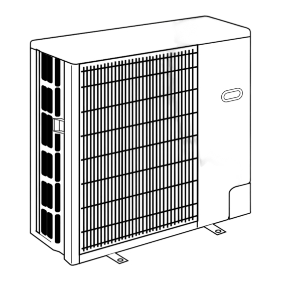
SPLIT-TYPE, HEAT PUMP AIR CONDITIONERS
TECHNICAL & SERVICE MANUAL
Outdoor unit
[model names]
PUH-P1.6VGA PU-P1.6VGA
PUH-P1.6YGA
PUH-P2VGA
PU-P2VGA
PUH-P2YGA
PUH-P2.5VGA PU-P2.5VGA
PUH-P2.5YGA
PUH-P3VGA
PU-P3VGA
PUH-P3YGA
PU-P3YGA
PUH-P4YGA
PU-P4YGA
PUH-P5YGA
PU-P5YGA
PUH-P6YGA
PU-P6YGA
Revision:
PUH-P1.6YGA, -P2YGA, -P2.5YGA,
PUH-P2.5VGA
, -P2.5YGA
1
PU-P1.6VGA, -P2VGA, -P2.5VGA,
PU-P3VGA, -P3YGA, -P4YGA, -P5YGA,
PU-P6YGA, -P2.5VGA
Revised Edition-A.
Please destroy OC180.
R407C
[Service Ref.]
PUH-P1.6VGA
PUH-P1.6YGA
PUH-P2VGA
PUH-P2YGA
PUH-P2.5VGA
PUH-P2.5VGA
PUH-P2.5YGA
PUH-P2.5YGA
PUH-P3VGA
PUH-P3YGA
PUH-P4YGA
PUH-P5YGA
PUH-P6YGA
and
1
added in
1
PU-P1.6VGA
PU-P2VGA
PU-P2.5VGA
PU-P2.5VGA
1
1
PU-P3VGA
PU-P3YGA
PU-P4YGA
PU-P5YGA
PU-P6YGA
CONTENTS
1. SAFETY PRECAUTION··································3
3. PART NAMES AND FUNCTIONS ··················5
4. SPECIFICATIONS···········································6
5. DATA ·····························································12
6. OUTLINES AND DIMENSIONS····················15
7. WIRING DIAGRAM ·······································19
8. REFRIGERANT SYSTEM DIAGRAM ·············23
9. DISASSEMBLY PROCEDURE ·····················25
10. PARTS LIST ··················································29
11. OPTIONAL PARTS ························Back cover
1999
No.OC180
REVISED EDITION-A
1
Advertisement
Table of Contents

Related Manuals for Mitsubishi Electric PU-P2VGA


Summary of Contents for Mitsubishi Electric PU-P2VGA
-
Page 1: Table Of Contents
SPLIT-TYPE, HEAT PUMP AIR CONDITIONERS No.OC180 REVISED EDITION-A TECHNICAL & SERVICE MANUAL R407C Outdoor unit [model names] [Service Ref.] PUH-P1.6VGA PU-P1.6VGA PUH-P1.6VGA PU-P1.6VGA PUH-P1.6YGA PUH-P1.6YGA PUH-P2VGA PU-P2VGA PUH-P2VGA PU-P2VGA PUH-P2YGA PUH-P2YGA PUH-P2.5VGA PU-P2.5VGA PUH-P2.5VGA PU-P2.5VGA PUH-P2.5VGA PU-P2.5VGA PUH-P2.5YGA PUH-P2.5YGA PUH-P2.5YGA PUH-P3VGA... -
Page 3: Safety Precaution
SAFETY PRECAUTION Cautions for using with the outdoor unit which adopts R407C refrigerant. · Do not use the existing refrigerant piping. -The old refrigerant and refrigerant oil in the existing piping contains a large amount of chlorine which may cause the refriger- ant oil of the new unit to deteriorate. - Page 4 [1] Service tools Use the below service tools as exclusive tools for R407C refrigerant. Tool name Specifications Gauge manifold ·Only for R407C. ·Use the existing fitting SPECIFICATIONS. (UNF7/16) ·Use high-tension side pressure of 3.43MPa·G or over. Charge hose ·Only for R407C. ·Use pressure performance of 5.10MPa·G or over.
-
Page 5: Combination Of Indoor And Outdoor Units
COMBINATION OF INDOOR AND OUTDOOR UNITS Outdoor unit Indoor unit Heat pump type Cooling only type PUH-P PU-P Service 6 1.6 2 2.5 Service Ref. Manual No. · REVISED PLH-P OC181 — — — — — — — — EDITION-A ·... -
Page 6: Specifications
SPECIFICATIONS 1.Heat pump Service Ref. PUH-P1.6VGA / YGA PUH-P2VGA / YGA PUH-P2.5VGA / YGA Cooling Heating Cooling Heating Cooling Heating Function Single, 50Hz, 220-240V/3-ph, 50Hz, 380-415V(4wires) Power supply (phase, cycle, voltage) 1.71 1.83 2.48 2.57 2.63 2.58 Input Running current 7.66 / 2.67 8.19 / 2.86 11.11 / 3.88... - Page 7 Service Ref. PUH-P3VGA / YGA PUH-P4YGA Function Cooling Heating Cooling Heating Power supply (phase, cycle, voltage) Single, 50Hz, 220-240V/3-ph, 50Hz, 380-415V(4wires) 3-ph, 50Hz, 380-415V(4wires) Input 3.34 3.52 3.36 3.54 14.64 / 5.46 15.43 / 5.76 5.49 5.79 Running current 93 / 41 Starting current Munsell 5Y 8/1 External finish...
- Page 8 Service Ref. PUH-P5YGA PUH-P6YGA Function Cooling Heating Cooling Heating 3-ph, 50Hz, 380-415V(4wires) Power supply (phase, cycle, voltage) Input 5.25 5.47 6.36 6.43 8.39 8.74 10.17 10.28 Running current Starting current Munsell 5Y 8/1 External finish Refrigerant control Linear Expansion Valve Hermetic Compressor Model...
- Page 9 2. Cooling only type Service Ref. PU-P1.6VGA PU-P2VGA PU-P2.5VGA Cooling Cooling Cooling Function Single, 50Hz, 220-240V Power supply (phase, cycle, voltage) Input 1.71 2.48 2.63 7.66 11.11 11.78 Running current Starting current Munsell 5Y 8/1 External finish Refrigerant control Linear Expansion Valve...
- Page 10 Service Ref. PU-P3VGA / YGA PU-P4YGA Cooling Cooling Function Single, 50Hz, 220-240V/3-ph, 50Hz, 380-415V(4wires) Power supply (phase, cycle, voltage) 3-ph, 50Hz, 380-415V(4wires) 3.34 3.36 Input 14.64/5.46 5.49 Running current 93/41 Starting current Munsell 5Y 8/1 External finish Refrigerant control Linear Expansion Valve Hermetic Compressor Model...
- Page 11 Service Ref. PU-P5YGA PU-P6YGA Cooling Cooling Function 3-ph, 50Hz, 380-415V(4wires) Power supply (phase, cycle, voltage) 5.25 6.36 Input Running current 8.39 10.17 Starting current Munsell 5Y 8/1 External finish Linear Expansion Valve Refrigerant control Hermetic Compressor Model HE86YAA HE101YAA Motor output Starter type Line start Internal thermostat, Anti-phase protector, thermal relay, HP switch, Discharge thermo, LP switch...
-
Page 12: Data
DATA 1. REFILLING REFRIGERANT CHARGE (R407C : kg) Piping length (one way) Factory Service Ref. charged PUH-P1.6VGA — PU-P1.6VGA PUH-P1.6YGA — PUH-P2VGA — PU-P2VGA PUH-P2YGA — PUH-P2.5VGA PU-P2.5VGA PUH-P2.5YGA PUH-P3VGA PU-P3VGA PUH-P3YGA PU-P3YGA PUH-P4YGA PU-P4YGA PUH-P5YGA PU-P5YGA PUH-P6YGA PU-P6YGA 2. COMPRESSOR TECHNICAL DATA at 20˚C... - Page 13 3. NOISE CRITERION CURVES PUH-P1.6VGA / YGA PUH-P2VGA / YGA SPL(dB) LINE SPL(dB) LINE NOTCH NOTCH COOLING COOLING PU-P2VGA PU-P1.6VGA HEATING HEATING NC-70 NC-70 NC-60 NC-60 NC-50 NC-50 NC-40 NC-40 NC-30 NC-30 APPROTIMATE APPROTIMATE TERESHOLD OF TERESHOLD OF REARING FOR...
- Page 14 PUH-P4YGA PUH-P5YGA SPL(dB) LINE SPL(dB) LINE NOTCH NOTCH COOLING COOLING PU-P4YGA PU-P5YGA HEATING HEATING NC-70 NC-70 NC-60 NC-60 NC-50 NC-50 NC-40 NC-40 NC-30 NC-30 APPROTIMATE APPROTIMATE TERESHOLD OF TERESHOLD OF REARING FOR REARING FOR NC-20 NC-20 CONTINUOUS CONTINUOUS NOISE NOISE 1000 2000 4000...
-
Page 15: Outlines And Dimensions
OUTLINES AND DIMENSIONS PUH-P1.6VGA, PU-P1.6VGA Unit : mm PUH-P1.6YGA... - Page 16 PUH-P2VGA, PU-P2VGA Unit : mm PUH-P2YGA PUH-P2.5VGA, PU-P2.5VGA PUH-P2.5VGA , PU-P2.5VGA PUH-P2.5YGA PUH-P2.5YGA PUH-P3VGA PUH-P3YGA PU-P3VGA PU-P3YGA...
- Page 17 PUH-P4YGA, PU-P4YGA Unit : mm...
- Page 18 PUH-P5YGA, PU-P5YGA Unit : mm PUH-P6YGA, PU-P6YGA...
-
Page 19: Wiring Diagram
WIRING DIAGRAM PUH-P1.6 / 2 / 2.5 / 3VGA PUH-P2.5VGA... - Page 20 PUH-P1.6 / 2 / 2.5 / 3 / 4 / 5 / 6YGA PUH-P2.5YGA...
- Page 21 PU-P1.6 / 2 / 2.5 / 3VGA PU-P2.5VGA...
- Page 22 PU-P3 / 4 / 5 / 6YGA...
-
Page 23: Refrigerant System Diagram
REFRIGERANT SYSTEM DIAGRAM PUH-P1.6VGA / PUH-P2VGA / PUH-P2.5VGA / PUH-P2.5VGA / PUH-P3VGA PUH-P1.6YGA / PUH-P2YGA / PUH-P2.5YGA / PUH-P2.5YGA / PUH-P3YGA <4-way valve solenoid coil> Heating : ON High pressure Outdoor unit Refrigerant pipe Cooling : OFF 4-way valve protect switch Indoor unit Outdoor heat exchanger 15.88A({5/8") - Page 24 PU-P1.6VGA / PU-P2VGA / PU-P2.5VGA / PU-P2.5VGA / PU-P3VGA / PU-P3YGA High pressure Outdoor unit Refrigerant pipe protect switch Indoor unit Outdoor heat exchanger 15.88A({5/8") Ball valve (with heat insulator) Strainer Thermistor (TH6) Flexible tube Thermistor Service Thermistor (TH1) Service...
-
Page 25: Disassembly Procedure
DISASSEMBLY PROCEDURE PUH-P5/6YGA OPERATING PROCEDURE PHOTOS 1. Removing the Service panel and Top panel Photo 1 Top panel screws (1) Remove the 3 service panel fixing screws (5 15) and Top panel slide the hook to remove the service panel. (2) Remove the screws (3 for front, 2 for rear/5 15) of the top panel and remove it. - Page 26 OPERATING PROCEDURE PHOTOS 4. Removing the liquid temperatuer thermistor, discharge Photo 4 temperatuer thermistor and condenser/evaporator temperature thermistor (1) Remove the service panel. (See Photo 1) Clamp (2) Remove the top panel. (See Photo 1) (When the top panel removing is not possible, remove Condenser/evaporator the electric parts box.
- Page 27 OPERATING PROCEDURE PHOTOS 9. Removing the pressure switch Photo 6 <Low pressure> (1) Remove the service panel. (See Photo 1) (2) Remove the top panel. (See Photo 1) (3) Remove the electrical box. (See Photo 3) (4) Disconnect the lead wire of the pressure switch. (See Photo 4) (5) Remove the braze part of the pressure switch.
- Page 28 OPERATING PROCEDURE PHOTOS 12. Removing the compressor Photo 8 (1) Remove the service panel. (See Photo 1) (2) Remove the top panel. (See Photo 1) (3) Remove the electric parts box. (See Photo 3) (4) Remove the bell mouth. (See Photo 7) (5) Remove the 3 valve bed fixing screws (4 10) and the 4 ball valve fixing screws(5...
-
Page 29: Parts List
PARTS LIST STRUCTURAL PARTS PUH-P1.6VGA PUH-P1.6YGA PU-P1.6VGA Price ty/set Wining Recom- Remarks Part No. Part Name Specification PUH-P1.6 PU-P1.6 Diagram mended (Drawing No.) Unit Amount Symbol VGA YGA VGA R01 30L 641 TOP PANEL (5 15) (DF12F536H15) — F.ST SCREW R01 31L 658 COVER PANEL-1 T7W E01 675... - Page 30 STRUCTURAL PARTS PUH-P2VGA, PU-P2VGA PUH-P2.5VGA, PU-P2.5VGA PUH-P2.5VGA , PU-P2.5VGA PUH-P3VGA, PU-P3VGA 7 13 ty/set Price Wining Recom- Remarks PUH-P / PU-P Part No. Part Name Specification Diagram mended (Drawing No.) Unit Amount Symbol R01 30L 641 TOP PANEL (5 15) (DF12F536H15) —...
- Page 31 STRUCTURAL PARTS PUH-P2YGA PUH-P2.5YGA PUH-P2.5YGA PUH-P3YGA, PU-P3YGA 7 13 ty/set Price Wining Recom- PUH-P PU-P Remarks Part No. Part Name Specification Diagram mended (Drawing No.) Unit Amount Symbol YGA YGA R01 30L 641 TOP PANEL — F.ST SCREW (5 15) (DF12F536H15) R01 31L 658 COVER PANEL-1...
- Page 32 STRUCTURAL PARTS PUH-P4YGA, PU-P4YGA 12 18 ty/set Price Recom- Wining Remarks PU(H)-P4 Specification Part No. Part Name mended Diagram (Drawing No.) Symbol Unit Amount R01 30L 641 TOP PANEL (5 15) (DF12F536H15) — F.ST SCREW R01 31L 658 COVER PANEL-1 T7W E03 675 FAN GUARD R01 30L 655...
- Page 33 STRUCTURAL PARTS PUH-P5YGA, PU-P5YGA PUH-P6YGA, PU-P6YGA ty/set Price Wining Recom- Remarks PU(H)-P5 PU(H)-P6 Part No. Part Name Specification Diagram mended Symbol (Drawing No.) Unit Amount R01 17T 641 TOP PANEL (5 15) (DF12F536H15) — F.ST SCREW R01 31L 658 COVER PANEL-1 T7W E03 675 FAN GUARD R01 30L 655...
- Page 34 FUNCTIONAL PARTS PUH-P1.6VGA, PU-P1.6VGA PUH-P1.6YGA PUH-P1.6YGA only...
- Page 35 ty/set Price Wining Recom- Remarks Part No. Part Name Specification Diagram mended P1.6 Symbol Unit Amount VGA YGA VGA PA6V85-UH T7W E03 763 OUTDOOR FAN MOTOR R01 30L 115 PROPELLER FAN T7W E01 315 OUTDOOR CONTROLLER BOARD T7W E02 315 OUTDOOR CONTROLLER BOARD T7W 520 239 250V 6.3A...
- Page 36 FUNCTIONAL PARTS PUH-P2VGA, PU-P2VGA PUH-P2.5VGA, PU-P2.5VGA PUH-P2.5VGA , PU-P2.5VGA PUH-P3VGA, PU-P3VGA 22 23...
- Page 37 ty/set Price Wining PUH-P PU-P Recom- Remarks Part No. Part Name Specification Diagram mended 2.5V 2.5V Symbol Unit Amount GAGAGA GAGAGA T7W E04 763 OUTDOOR FAN MOTOR PA6V85-UH R01 30L 115 PROPELLER FAN T7W E01 315 OUTDOOR CONTROLLER BOARD T7W 520 239 FUSE 250V 6.3A FUSE...
- Page 38 FUNCTIONAL PARTS PUH-P2YGA PUH-P2.5YGA PUH-P2.5YGA PUH-P3YGA, PU-P3YGA 23 24...
- Page 39 ty/set Price Wining PUH-P PU-P Recom- Remarks Part No. Part Name Specification Diagram mended 2.5Y Symbol Unit Amount GA GA T7W E04 763 OUTDOOR FAN MOTOR PA6V85-UH R01 30L 115 PROPELLER FAN T7W E02 315 OUTDOOR CONTROLLER BOARD T7W 520 239 FUSE 250V 6.3A FUSE...
- Page 40 FUNCTIONAL PARTS PUH-P4YGA, PU-P4YGA...
- Page 41 ty/set Price Wining Recom- Remarks Part No. Part Name Specification Diagram mended Symbol Unit Amount P4YGA T7W E05 763 OUTDOOR FAN MOTOR PA6V70-UA T7W E03 763 OUTDOOR FAN MOTOR PA6V70-UC R01 30L 115 PROPELLER FAN T7W E02 315 OUTDOOR CONTROLLER BOARD FUSE T7W 520 239 FUSE...
- Page 42 FUNCTIONAL PARTS PUH-P5YGA, PU-P5YGA PUH-P6YGA, PU-P6YGA...
- Page 43 ty/set Price Wining Recom- Remarks Part No. Part Name Specification Diagram mended Symbol Unit Amount T7W E07 763 OUTDOOR FAN MOTOR PA6V75-UA T7W E06 763 OUTDOOR FAN MOTOR PA6V75-UB R01 30L 115 PROPELLER FAN T7W E02 315 OUTDOOR CONTROLLER BOARD T7W 520 239 FUSE FUSE...
-
Page 44: Optional Parts
Applied models PU(H)-P • GA HEAD OFFICE MITSUBISHI DENKI BLDG.MARUNOUCHI TOKYO100-8310 TELEX J24532 CABLE MELCO TOKYO cCopyright 1999 MITSUBISHI ELECTRIC ENGINEERING CO., LTD. Issued in Feb. 2000 No.OC180 REVISED EDITION-A 42 New publication, effective Feb. 2000 Issued in Mar. 1999 No.OC180 36 Specifications subject to change without notice.
Need help?
Do you have a question about the PU-P2VGA and is the answer not in the manual?
Questions and answers