Centurion Vector2 Installation Manual
Centurion linear swing gate operator
Hide thumbs
Also See for Vector2:
- Installation manual (82 pages) ,
- User manual (40 pages) ,
- User manual (40 pages)
Table of Contents
Advertisement
Advertisement
Table of Contents

Related Manuals for Centurion Vector2


Summary of Contents for Centurion Vector2
- Page 1 VECTOR2 installation manual LINEAR SWING GATE OPERATORS...
-
Page 2: Company Profile
50 countries worldwide CENTURION SYSTEMS (Pty) Ltd reserves the right to make changes to the products described in this manual without notice and without obligation of CENTURION SYSTEMS (Pty) Ltd to notify any persons of any such revisions or changes. -
Page 3: Table Of Contents
Contents Mechanical Setup page 1 Electrical Setup Page 2 Commissioning and handover page 2 page 3 IMPORTANT SAFETY INSTRUCTIONS Declaration of conformity page 5 General description page 6 Lightning protection page 7 Icons used in this booklet page 7 Specifications page 8 Physical dimensions page 8... - Page 4 18. Wiring diagram for Slave motor (MTRS) page 42 19. Charger and Pillar Light connections page 43 20. Setting up additional features page 44 21. Menu navigation map page 45 22. Controller features page 48 23. Factory defaults schedule page 58 24.
-
Page 5: Mechanical Setup
Mechanical setup These quick steps are for the experienced installer who needs a checklist to get a standard installation up and running in the minimum of time. Detailed installation features and functions are referred to later in this manual. Gather required tools and equipment Page 14 Heed necessary site considerations Page 15... -
Page 6: Electrical Setup
Electrical setup Set limit switches and/or fit Page 36 mechanical endstops Commissioning and handover Commission system Page 70 Carry out professional handover to Page 70 client Page 2... -
Page 7: Important Safety Instructions
IMPORTANT Safety Instructions ATTENTION To ensure the safety of people, it is important that you read all the following instructions. Incorrect installation or incorrect use of the product could cause serious harm to people. The installer, being either professional or DIY, is the last person on the site who can ensure that the operator is safely installed, and that the whole system can be operated safely. - Page 8 Always check the obstruction detection system, and safety devices for correct operation Centurion Systems does not accept any liability caused by improper use of the product, or for use other than that for which the automated system was intended This product was designed and built strictly for the use ...
-
Page 9: Declaration Of Conformity
Unit 13 Production Park Intersection Newmarket Road & Epsom Avenue North Riding Gauteng South Africa Declares that the product: Product name: VECTOR2 Swing gate operator Product options: All variants Conforms with the following specifications: Safety: SANS 60335-1:2007 IEC 60335-1:2006 Emissions: CISPR 22 CLASS B: Radiated emissions –... -
Page 10: General Description
The VECTOR2 control card has been designed to be easy and intuitive to use with helpful instructions on the status of the operation during and after the installation. It also has a built-in diagnostic procedure that can verify every aspect of the control card on site. -
Page 11: Lightning Protection
The VECTOR2 electronic controller utilises the same proven surge protection philosophy that is used in all CENTURION products. While this does not guarantee that the unit will not be damaged in the event of a lightning strike or power surge, it greatly reduces the likelihood of such damage occurring. -
Page 12: Specifications
4. Specifications Physical dimensions Model V400 1400mm Extended 1400mm Extended 1000mm Retracted 1000mm Retracted 400mm Stroke 400mm Stroke All dimensions shown in millimeters FIGURE 1. OVERALL DIMENSIONS Model V500 1600mm Extended 1600mm Extended 1100mm Retracted 1100mm Retracted 500mm Stroke 500mm Stroke All dimensions shown in millimeters FIGURE 2. -
Page 13: Technical Specifications
Double kit 14kg 15kg Can operate off a solar supply, consult Centurion Systems for assistance Can increase battery capacity for longer standby times Based on 25°C ambient temperature and unit not in direct sunlight Based on an operator push force of less than 50% of rated Based on double kit excluding infrared safety beams Assumes a 90°... -
Page 14: Control Card
Control card Maximum motor current per channel 15A (fused) Maximum input voltage 14.4V DC Standby current draw 48mA Maximum solenoid current draw 2A DC Maximum aux output current 3A (PTC) Collision detection Current sense and redundant optical Position and trajectory Redundant optical Temperature range -20°C to +60°C... -
Page 15: Allowable Gate Mass
Allowable gate mass Maximum allowable gate mass for V400 operator: Gate swing angle Up to Up to Up to Upto Up to Up to 1.5m 2.5m 3m(#1) 3.5m(#1) 4m(#1) 90° 500kg 500kg 500kg 360kg 260kg 200kg 100° 500kg 500kg 388kg 160kg 190kg 150kg... -
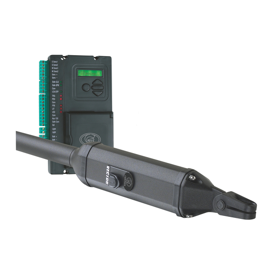
Page 16: Product Identification
5. Product identification FIGURE 3. PRODUCT IDENTIFICATION Wall bracket (standard) Gate operator keys Wall bracket pin Gate bracket VECTOR2 gate operator (complete Stainless steel cap screw M6 x 25 assembly) 10. Origin body 12mm snap ring 11. Stainless steel M6 nut Gate warning decal 12. - Page 17 FIGURE 3B. WALL ADAPTOR KIT VECTOR2 wall adaptor kit packing leaflet Wall adaptor plate M10 Hexagon nuts M10 x 20 Countersunk screw FIGURE 3C. HIGH SECURITY KIT VECTOR2 high security kit packing leaflet Wall bracket (high security) Padlock FIGURE 3D. MECHANO KIT...
-
Page 18: Required Tools And Equipment
6. Required tools and equipment Spanner - 17mm, 15mm, preferably socket set Crimping tool and pin lugs Hammer Electric drilling machine 20mm hole saw Screwdrivers - 6mm Philips, 3.5 Flat Pliers Connector block ... -
Page 19: Preparation Of Site
7. Preparation of site General considerations for the installation Always recommend the fitment of additional safety equipment such as safety edges and safety beams, for additional protection against entrapment or other mechanical risks Check that no pipes or electrical cables are in the way of the intended installation ... -
Page 20: Strength Of The Pillar
Pillar (maximum) Wall (minimum) Gate opening 110° Gate opening Operator Wall (minimum) Pillar (maximum) 110° V400 150mm 145mm V500 150mm 210mm FIGURE 5 Tables are based on gates shorter than 2.5m For gates 2.5m to 3.0m long, reduce the maximum pillar thickness by 20mm ... - Page 21 Pillar High Security Kit This mounting works well for heavy gates shorter than about 2m in single household Wall domestic applications. adaptor (high security) Alternatively it should be considered for use on pillars of low or unknown strength. Works well FIGURE 7 Pillar Standard bracket...
- Page 22 Pillar Welding Applications: Lighter gates Wall Welding adaptor machine (high Domestic security) Works well FIGURE 11 Pillar Sleeve anchors Applications: Wall adaptor Lighter gates (high security) Domestic Sleeve anchor FIGURE 12 Pillar RAWL Bolts Applications: Wall adaptor Very light (high...
-
Page 23: Strength Of The Gate And Gate Bracket
Strength of the gate and gate bracket The gate adaptor kit both strengthens the connection to the gate, and also allows for more flexibility when mounting the bracket to the gate: Welding Gate adaptor kit Applications: Gate Light-industrial Heavy gates Welding ... -
Page 24: The Mechano Kit Installation Options
The Mechano kit installation options This kit is useful when fitting VECTOR2 to existing installations, and also makes adjustments easier when doing new installations. FIGURE 18. INSTALLATION WHEN THE PILLAR IS WIDE FIGURE 19. INSTALLATION WHEN THE PILLAR IS AN IRREGULAR SURFACE FIGURE 20. - Page 25 FIGURE 22. INSTALLATION WHEN THE PILLAR IS WIDE FIGURE 23. INSTALLATION WHEN THE PILLAR IS IRREGULAR SURFACE FIGURE 24. INSTALLATION ON A PALISADE FENCE FIGURE 25. INSTALLATION ON AN ANGLED WALL Page 21...
-
Page 26: Cabling Requirements
Domestic charger only. For optimum range an external receiver can be mounted on the wall. CENTURION has available custom VECTOR2 cable order reference: CABLEVEC68 Consult manufacturer of loop detector for specific details All cables must be routed in conduit unless underground cable is being used ... -
Page 27: Operator Installation
9. Operator installation To simplify the installation process, it is recommended that the existing gate is removed from the pillar before proceeding. Closed 1. Determine gate opening angle and direction of operator (inward or outward). Alternatively the swing angle can be 120°... -
Page 28: Determine The Gate Bracket Position
FIGURE 31 Determine the gate Gate bracket bracket position Start with the operator fully retracted VECTOR2 unit Turn out the actuator tube one or two turns One or two turns 5. Fit the gate bracket to the operator. Origin marker... - Page 29 8. Unlock the operator and swing the gate closed. 9. Remove the pin and the operator from the bracket, check that there are at least one or two turns of the actuator before it is fully FIGURE 35 extended. If it becomes obvious that the operator does not have enough Gate stroke, reduce either the A or B...
-
Page 30: Adjust Origin Clamp
12. Fit operator, gate bracket pins and snap rings. Wall adaptor (standard) As an alternative to the snap ring, fit VECTOR2 a padlock Padlock operator FIGURE 39 Adjust origin clamp 13.Unlock the operator and open the gate fully. 14. Slide the origin clamp along the actuator tube, right up to the operator. -
Page 31: Inward Swing Gate Setup
Inward swing gate Setup Gate closed FIGURE 42 For gates opening 90° or less For best security (but slower operation) install with large B value For fast operation (but less FIGURE 43 security) install with small A and small B values Ensure that the gate does not exceed the gate mass specifications on page 11... - Page 32 For V400 (400mm operator) 1400mm Extended 1000mm Retracted 1000mm Retracted FIGURE 45 Recommended positions 0° Gate opening angle (Only for a 2.5m gate or shorter) Gate swing angle A Value B Value 90° or less 100° 110° 120° 120° 60° 110°...
- Page 33 For V500 (500mm operator) 1600mm Extended 1100mm Retracted FIGURE 47 0° Recommended positions Gate opening angle (Only for a 2.5m gate or shorter) Gate swing angle A Value B Value 90° or less 100° 110° 120° 120° 60° 110° 70° 100°...
-
Page 34: Outward Swing Gate Setup
Outward swing gate Setup For gates opening 90° or less For best security (but slower Make up operation) install with large B value bracket to suit For fast operation (but less security) install with small A and FIGURE 49 small B values Ensure that the gate does not exceed the gate mass specifications on page 11... - Page 35 For V400 (400mm operator) 1400mm Extended 1000mm Retracted 1000mm Retracted FIGURE 52 0° Recommended positions Gate opening angle (Only for a 2.5m gate or shorter) Gate swing angle A Value B Value 90° or less 100° 110° 120° 120° 60° 110°...
- Page 36 For V500 (500mm operator) 1600mm Extended 1100mm Retracted FIGURE 54 0° Recommended positions Gate opening angle (Only for a 2.5m gate or shorter) Gate swing angle A Value B Value 90° or less 100° 110° 120° 120° 60° 110° 70° 100°...
-
Page 37: Determine Gate Swing Angle
10. Determine gate swing angle Use this procedure to accurately determine the gate opening angle: Step 1 1. Close the gate and measure a distance of 1m from the centreline of the gate hinge. 2. Make a mark on the ground. FIGURE 56 Step 2 3. -
Page 38: Allowable Wind Loading
11. Allowable wind load Wind speeds for which operator will still operate the gate (for V400 or V500 operators) For a 25% covered gate: (Palisades, etc.) x 1.8m high Gate lengths: Value of A or B dimension once Up to Up to Up to Up to... -
Page 39: Electrical Setup
12. Electrical setup 1. Always check that the circuit breaker in the electrical panel is in the OFF position, and that all high voltage circuits (more than 42.4V) are completely isolated from the mains supply before doing any work. 2. Ensure that all low voltage systems (less than 42.4V) are suitably protected from damage, by disconnecting all sources of power such as chargers and batteries before doing any work. -
Page 40: Setting The Limits
4. Check that the charger and battery are connected to the controller. Aux 12V Ensure the battery polarity is correct Com Saf Light 5. Switch on the mains supply (via isolator). Light Charger Batt + 6. Ensure that both the controller and charger Battery Batt - MTR M+... -
Page 41: Wiring Diagram For Closing Safety Beam
13. Wiring diagram for closing safety beam Closing safety beam 12V/24V - 12V/24V + 12V/24V + 12V/24V - FIGURE 65. WIRING OF SAFETY DEVICE Page 37... -
Page 42: Wiring Diagram For Opening Safety Beam
14. Wiring diagram for opening safety beam Opening safety beam 12V/24V - 12V/24V + 12V/24V + 12V/24V - FIGURE 66. WIRING OF SAFETY DEVICE Page 38... -
Page 43: Wiring Diagram For External Radio Receiver And Loop Detector
15. Wiring diagram for external radio receiver and loop detector Loop and loop detector 12V + External radio receiver 12V + Remote control circuitry Refer to diagram only if external receiver is being used and not the onboard receiver, disable onboard receiver - Menu 11 FIGURE 67. -
Page 44: Wiring Diagram For Other Inputs
16. Wiring diagram for other inputs Solenoid or strike lock Holiday Lockout keyswitch/keypad (normally-closed) Pedestrian keyswitch/keypad (normally-open) Pillar Light pushbutton (normally-open) CENTURION Status FIGURE 68. WIRING OF OTHER INPUTS Page 40... -
Page 45: Wiring Diagram For Master Motor (Mtrm)
17. Wiring diagram for Master motor (MTRM) S Sens1 S Sens2 Thin purple M Sens1 Thin blue / orange M Sens2 Thin red / grey Sens+ Thin black Sens- Safe CLS Safe OPN LCK/STP Aux 12V Safe Com Light Light Batt + Batt - Thick blue... -
Page 46: Wiring Diagram For Slave Motor (Mtrs)
18. Wiring diagram for Slave motor (MTRS) Thin purple S Sens1 Thin blue / orange S Sens2 M Sens1 M Sens2 Thin red / grey Sens+ Thin black Sens- Safe CLS Safe OPN LCK/STP Aux 12V Safe Com Light Light Batt + Batt - MTR M+... -
Page 47: Charger And Pillar Light Connections
19. Charger and Pillar Light connections S Sens1 S Sens2 M Sens1 M Sens2 Sens+ Sens- Safe CLS Safe OPN Auxiliary LCK/STP supply -240V AC Pillar Mains in Light Aux 12V Protection fuse on Safe Com mains input to Neutral Light charger (rating: Light... -
Page 48: Setting Up Additional Features
An explanation of each feature is provided in the section ‘Controller features’. When setting up the VECTOR2 system via the LCD display, all the steps that have to be When setting up the VECTOR2 system via the LCD display, all the steps that have to be followed are clearly provided via the display. -
Page 49: Menu Navigation Map
21. Menu navigation map Setting limits 1.1. Setup wizard Safety 2.1. MTRM Collision Force 2.1.1. MTRM Opening Collision Force 2.1.2. MTRM Closing Collision Force 2.2.1. MTRS Opening Collision 2.2. MTRS Collision Force Force 2.2.2. MTRS Closing Collision Force 2.3. Collision Count Autoclose 3.1. - Page 50 Leaf delay 2.1.1. Leaf Delay Status 2.2.1. Leaf Delay Value 5.2. Pre-open delay 5.3. Pre-close delay Opening speed 5.5. Closing speed 5.6. Ramp-up distance 5.7. Ramp-down distance 5.8. TRG stop distance 5.9. IRB stop distance 5.10. Crawl distance 5.11. Torque limit Infrared beams 6.1.
- Page 51 Courtesy Light 9.1. Courtesy Light timer 9.2. Light profile 9.2.1. Courtesy Light 9.2.2. Pre-flash A 9.2.3. Pre-flash B 9.2.4. Pre-flash C Remote controls Press button of valid transmitter (if menu locked) 10.1. Add remotes 10.2.1.Delete by ID 10.2. Delete remotes 10.2.2.Delete button 10.2.3.Delete by button 10.3.
-
Page 52: Controller Features
22. Controller features Menu 2 - Safety (collision force) Collision force If the gate is obstructed, the internal collision circuitry will activate. The response of the system to a collision will vary, depending on the profile (operating standard, e.g. ZA,) selected. Responses can vary from the gate stopping, to the gate reversing. - Page 53 Autoclose on partly closed - automatically close the gate if it is stopped while closing, but before reaching the fully closed position More than one advanced option can be selected Menu 4 - Modes of Operation It is possible to select the following Modes of Operation: Standard, Condominium, Reversing, PLC and Deadman Control Mode (DCM).
- Page 54 Short Stop value Mechanical lip The Short Stop distance can be set between 1mm and 40mm of piston S Gate closes first stroke M gate closes PCM push force slightly behind The amount of force applied by the S Gate (Leaf delay) actuator when in PCM can be set as a value from 1 to 15...
- Page 55 Ramp-up distance Sets the ramp-up distance in millimeters of travel of the piston when starting. This setting applies to both motors Ramp-down distance Sets the ramp-down distance in millimeters of travel of the piston when stopping. This setting applies to both motors Crawl distance ...
- Page 56 Additional beam functionality is provided: PIRAC Outside closing beam The Passive-Infrared Autoclose feature allows the gate to close automatically, as soon as a vehicle or pedestrian has passed through the closing beam. This security feature ensures that the gate stays Inside closing beam open for the minimum amount of Opening beam...
- Page 57 IRBO=IRBC Configures the opening beam to act as a closing beam while the gates are closing. This allows one set of beams to be used across the line of the driveway up to where the gates open. IR beam alarms ...
- Page 58 Menu 7 - Pedestrian Opening This feature is associated with the Ped input on the controller. When activating this input, the system will open the gate to the pedestrian open position, and then automatically close after the Pedestrian Autoclose time lapses. If the Ped connection to Com is maintained, then the gate will remain open, and when the connection is broken, it will close after the Pedestrian Autoclose time has expired The time taken for the gate to open to pedestrian is dependent on the pedestrian...
- Page 59 Pre-release time Sets the time period (in 0.1s increments) for which the lock releases BEFORE the gate has started moving. This is useful in cases where premature gate movement prevents the lock from releasing Lock location Specifies whether the gate is locked while closed, open or both Lock drive ...
- Page 60 Menu 11 - Remote controls The controller is capable of learning up to 64 CENTURION NOVA remote controls / transmitters. Each transmitter can have up to four buttons. Each transmitter learned into the system is assigned a unique transmitter ID It is possible to artificially increase the number of buttons of a multi- ...
- Page 61 Another benefit of using the shift button system is that it requires both hands to operate the two button combination. This prevents the user from accidentally enabling sensitive functions such as Holiday Lockout on the controller Each transmitter learned into the system is assigned a unique ...
-
Page 62: Factory Defaults Schedule
23. Factory defaults schedule South African standard profile - ZA Parameter Description Unit Minimum Default Maximum Autoclose Enabled Yes/No Autoclose from Fully Open Yes/No Autoclose from Partly Open Yes/No Autoclose from Partly Closed Yes/No Autoclose Time Mm:ss 00:00* 0:15 04:00* Autoclose Override Time Mode of Operation S,R,C... - Page 63 South African standard profile - ZA (continued) Parameter Description Unit Minimum Default Maximum PED Open Distance % (Full Open) PED Autoclose Time PED Pre-Open Delay Time PED Pre-Close Delay Time Gate Lock Enabled Yes/No Gate Lock Type Striker Gate Lock Pre-Release Time 0.0 24.0 24.0 Gate Lock Release Time...
- Page 64 CE standard profile Parameter Description Unit Minimum Default Maximum Autoclose Enabled Yes/No Autoclose From Fully Open Yes/No Autoclose From Partly Open Yes/No Autoclose From Partly Closed Yes/No Autoclose Time Mm:ss 00:00 00:15 04:00 Autoclose Override Time Mode Of Operation S,R,C Standard Motor M Opening Force Level...
- Page 65 CE standard profile (continued) Parameter Description Unit Minimum Default Maximum PED Open Distance % (Full Open) PED Autoclose Time PED Pre-Open Delay Time PED Pre-Close Delay Time Gate Lock Enabled Yes/No Gate Lock Type Maglock Gate Lock Pre-Release Time 24.0 Gate Lock Release Time 24.0 Gate Lock Location...
- Page 66 UL325 standard profile Parameter Description Unit Minimum Default Maximum Autoclose Enabled Yes/No Autoclose From Fully Open Yes/No Autoclose From Partly Open Yes/No Autoclose From Partly Closed Yes/No Autoclose Time Mm:ss 00:00 00:15 04:00 Autoclose Override Time Mode Of Operation S,R,C Standard Motor M Opening Force Level...
- Page 67 UL325 standard profile (continued) Parameter Description Unit Minimum Default Maximum PED Open Distance % (Full Open) PED Autoclose Time PED Pre-Open Delay Time PED Pre-Close Delay Time Gate Lock Enabled Yes/No Gate Lock Type Maglock Gate Lock Pre-Release Time 24.0 Gate Lock Release Time 24.0 Gate Lock Location...
-
Page 68: Description Of Terminal Functions
24. Description of terminal functions S Sens1 Motor S (MTR S) operator. Connects to the thin PURPLE wire of the Motor S operator. S Sens2 Motor S (MTR S) operator. Connects to the thin BLUE or ORANGE wire of the Motor S operator. M Sens1 Motor M (MTR M) operator. - Page 69 Trigger input. (A normally-open potential-free input) Momentarily connecting this input to COM will cause the gate to open or close depending on the operating mode selected. For more information see the Autoclose feature and Modes of Operation Pedestrian opening input. (A normally-open potential-free input). Momentarily connecting this input to COM will cause one gate to open to the Pedestrian open position.
- Page 70 Light Pillar Light connection. These two terminals provide a normally-open potential-free contact which is generally used to switch on a Pillar Light (Courtesy Light). This contact is fuse protected – refer to page 41 for fuse specifications. Batt + Positive battery connection. (Battery terminal normally indicated as + or RED) Batt - Negative battery connection.
-
Page 71: Diagnostics
25. Diagnostics Diagnostic LEDs The controller is fitted with diagnostic lights (LEDs) that assist with the setup and maintenance of the gate. Figure 74 below provides a description and purpose of the indicator lights also indicating the location on the controller Safety close On when the closing beam is not activated Off when closing safeties obstructed... -
Page 72: Lcd Display
LCD display The LCD display shows useful information regarding the status of the system. S Sens1 S Sens2 M Sens1 0:00 M Sens2 CLOSED Sens+ Sens- Safe CLS Safe OPN LCK/STP FIGURE 75. CONTROLLER SCREEN 1. Battery icon Indicates the state of charge of the battery. Four solid bars = full capacity ... -
Page 73: Buzzer Feedback
Buzzer feedback The VECTOR2 controller is equipped with an onboard buzzer which is used for various features and functions on the controller. One of the functions it provides is audible diagnostic feedback as detailed Inhibitor Priority Number Fault Gate User can... -
Page 74: Installation Handover
Centurion Systems (Pty) Ltd does not accept any liability caused by improper use, of the product, or for use other than that for which the automated system was designed. - Page 75 Notes...
- Page 76 Sharecall 0860-CENTURION (0860 236 887) Head Office: +27 11 699 2400 Sharecall Technical Support 0861 003 123 or +27 11 699 2481 from 07h00 to 18h00 (GMT+2) (Sharecall numbers applicable when dialed from within South Africa only) 0.07.A.0012_22072013 www.centsys.com...
Need help?
Do you have a question about the Vector2 and is the answer not in the manual?
Questions and answers