Table of Contents
Advertisement
Quick Links
Advertisement
Table of Contents

Related Manuals for Cornelius UltraFlow


Summary of Contents for Cornelius UltraFlow
-
Page 2: Table Of Contents
Table of Content Page 0. Table of Content 1. Introduction 2. General Information 3. Safety 4. Handling and Transportation 5. Installation 6. Installation Procedure 7. Operation 8. Fault Finding 10-11 9. Parts Replacements 12-13 10. Technical Data 11. Wiring Schematic 12. -
Page 3: Introduction
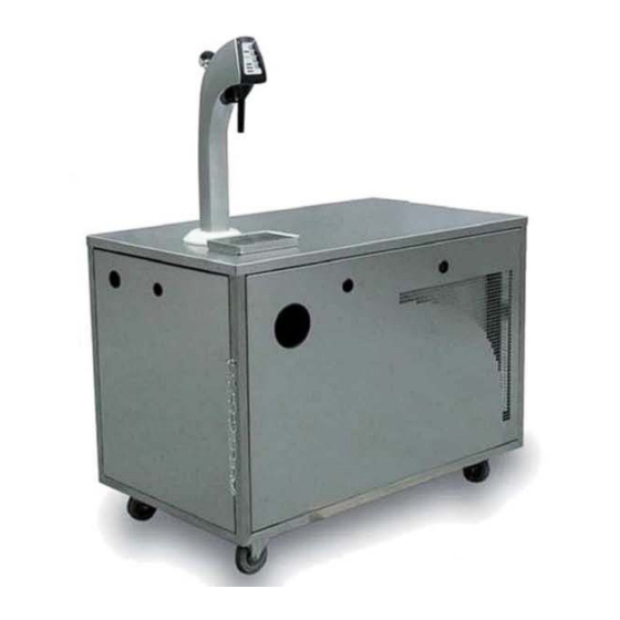
INTRODUCTION The UltraFlow dispensing and cooling system is a self-contained, high speed mobile solution for busy places. Developed to meet unique requirements of stadium and event outlets, it delivers beer to a maximum number of consumers in the shortest possible time. -
Page 4: Handling And Transportation
HANDLING AND TRANSPORTATION − This unit is heavy, take care when moving − Offload the unit from transport as close as possible to the site of intended use − Use the handles provided to move the unit − Move the unit no faster than walking pace −... -
Page 5: Installation Procedure
Installation − The appliance must be earthed − If not already fitted, fit the appropriate electrical plug to the service cord − The device must be in satisfactory condition whenever operated. Any modifications which detrimentally affect the safety of the device are therefore strictly prohibited. Please contact your service company if you wish to obtain more information about safety −... - Page 6 +5 psi Activate the pint portion. Check correct operation and ensure the product pipes are fully primed. Check portions are correct using a marked container. Commissioning UltraFlow font (see Operation)
-
Page 7: Operation
OPERATION Programming Normal display will read “Ready” Press and hold “Cancel” button (red lights will alternate on Keg and gas empty) Display will show pint and jugs dispensed. (these readings cannot be altered). Press “Portion 2” button to scroll trough the menu: Press “Portion 2”... - Page 8 − Isolate the power supply to the unit during maintenance operations − Only use Cornelius parts for cooler maintenance. Failure to do so will invalidate approvals and warranty PREVENTATIVE USER MAINTENANCE For all of the below, once the maintenance is carried out, follow the Installation instructions for re commissioning the unit −...
- Page 9 − Pull the mains plug out of socket − Detach the couplings from beverage containers & CO2 cylinder. − Pull the UltraFlow tower out of the socket and lay it down on the top of the mobile bar and fix...
-
Page 12: Parts Replacements
Parts replacement... -
Page 14: Technical Data
Technical data... -
Page 15: Wiring Schematic
Wiring Schematic / System Schematic... -
Page 16: Spare Parts List
Spare parts list CR11 Cooler Item Part code Description 220055105 BASE SHEET CR11 143277000 ADJUSTING FOOT 220055074 OVERFLOW TRAY CHROME - SC 440000236 COMPRESSOR GS 34 TB 189722000 BOLT 131706000 BUFFER VIBRATION 32x23 187888000 CLAMP 440000704 CONDENSER STVF 273 220055172 WATERBATH CR11 220055102S010 SHEET METAL HOUSING WATERBATH TRITON 250... -
Page 19: Model Written Scheme Of Examination
Model Written Scheme of Examination for Mobile “Player” Bar This scheme should be completed by the nominated technical person or by a technician on behalf of the nominated technical person. Notes on BBPA Code of Practice Competent Person The design, installation and use of equipment for the pressurised dispense of beer and cider all come to some degree under the Pressure Equipment Regulations 1999, SI 1999 No. - Page 20 Written Scheme of Examination for Mobile Dispense system Using Top Pressure Used in the storage and dispense of Draught Beers Wines and Ciders Written scheme number Prepared for: Company Name Company Address Post Code By Dick Ward IMI Cornelius UK Ltd Tything Road Alcester Warks. B49 6EU Tel 01789 763101...
- Page 21 Name and Address of Owner Name Address Post Code Tel. Fax. Pressure System Types 1 Carbon Dioxide Pressure System 2 Carbon-Dioxide/Nitrogen Mixed Gas System Location of Records Address(es) of Record Locations Tel : Fax : Scope of this Written Scheme of Examination This Written Scheme of Examination applies to mobile pressure systems that:...
- Page 22 a) are operated within licensed event areas. b) Are used for distribution of top pressure gases used for the storage and dispense of draught c) beers, wines and ciders; and d) Fall within the requirements of “The Pressure Systems Safety Regulations, 2000”.
- Page 23 The pressure systems used for the storage and dispense of draught beers, wines and ciders are simple. They must comply with legislation. The following Regulations concern the pressure systems, and the components used in their assembly: 1) The Pressure Systems Safety Regulations 2000 (SI2000 No. 128) 2) The Pressure Equipment Regulations 1999 (SI 1999 No.2001) 3) “The Carriage of Dangerous Goods and Use of Transportable Pressure Equipment Regulations 2004”...
- Page 24 Table 1 : Description of Blocks in Figure 1 BLOCK CHARACTERISTICS Pressure Source CO2 Cylinder; Mixed Gas Cylinder Primary Reducing Inlet max. allowable pressure: to suit pressure source; System/ Capacity: max. 66 litres/minute with full cylinder. Primary Safety Maximum allowable outlet pressure to secondary: Valves 150 psig for all gases.
- Page 25 Examples of such items of plant not requiring periodic examination under this written scheme include: Gas piping and tubing; piping/tubing/line fittings; secondary pressure reducing valves. Plant and Pressure Systems not included in this written Scheme of Examination This written Scheme of Examination does not cover: Any part of the mobile equipment of which the Brewery Company Name/Supplier is neither the owner or user.
- Page 26 Examination by Replacement Preparation: Prior to removal of any component part of the pressure system, the system should be isolated from any source of pressure and the internal pressure relieved. Removal: The part, or assembly of parts, specified to be “examined by replacement” shall be removed with care and diligence so as not to cause any damage or deterioration to either the parts or connecting parts in the system.
- Page 27 3.5 Response to Imminent Danger: The competent person must, in the event of discovering a material condition which could give rise to imminent danger, inform the owner/owner representatives of the condition and ensure the unit is taken out of use until such condition/s has been rectified.
Need help?
Do you have a question about the UltraFlow and is the answer not in the manual?
Questions and answers