Table of Contents
Advertisement
Quick Links
Smart Touch Cabin Control
Installation & Operations Manual
Dometic Corporation
Rev. 20150220
L-3380 English
P/N 337767
COPYRIGHT © 2011-2015 Dometic Corporation. All Rights Reserved.
No part of this publication may be reproduced, translated, stored in a retrieval system, or transmitted in any form or by any means
electronic, mechanical, photocopying, recording or otherwise without prior written consent by Dometic Corporation. Every precaution
has been taken in the preparation of this manual to insure its accuracy. However, Dometic Corporation assumes no responsibility for
errors and omission. Neither is any liability assumed for damages resulting from the use of this product and information contained
herein.
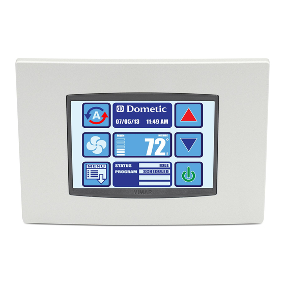
Smart Touch Cabin Control
(shown in optional white bezel)
Advertisement
Table of Contents

Related Manuals for Dometic Smart Touch Cabin Control


Summary of Contents for Dometic Smart Touch Cabin Control
- Page 1 Dometic Corporation. Every precaution has been taken in the preparation of this manual to insure its accuracy. However, Dometic Corporation assumes no responsibility for errors and omission. Neither is any liability assumed for damages resulting from the use of this product and information contained...
-
Page 2: Table Of Contents
Table of Contents INTRODUCTION ....... 1 ......9 . -
Page 3: Introduction
Read this manual completely before you proceed with the installation and operation of the Smart Touch. If you have questions or require assistance with your Smart Touch control, contact the Dometic Marine Service Department at +1 954-973-2477. The Smart Touch is covered under existing Marine Air Systems Warranty Policy. Incorrect installation, neglect and system abuse are not covered under Marine Air Systems warranty policy. -
Page 4: Description Of Control
INTRODUCTION Smart Touch Cabin Control Installation & Operations Manual ESCRIPTION OF ONTROL See Figures 1, 2 to identify Home and Main screen displays. Figure 1: Smart Touch Home Screen Smart Touch Home Screen Display Layout Temperature Indicator icon (Inside, set point, outside, and water temperatures) -
Page 5: Important Programming
INTRODUCTION Smart Touch Cabin Control Installation & Operations Manual MPORTANT ROGRAMMING OTES TO NSTALLER AND If your air conditioning unit is Cool only (if it does not have a reversing valve), then you MUST select Cool Only Mode. DO NOT select Automatic Mode for a Cool Only unit. If Automatic Mode is selected and the thermostat calls for heat, the compressor will run. -
Page 6: Installing The Display Panel
INSTALLING THE DISPLAY PANEL Smart Touch Cabin Control Installation & Operations Manual INSTALLING THE DISPLAY PANEL HOOSING THE OCATION Figure 3: Smart Touch Display Front Panel Before mounting the control panel, consider the location. The display panel’s built-in air sensor provides excellent room-air temperature sensing when properly located and installed. -
Page 7: Ounting The Remote Air Sensor
INSTALLING THE DISPLAY PANEL Smart Touch Cabin Control Installation & Operations Manual Secure the display panel to the bulkhead using the four screws provided. Do not use a screw gun and do not overtighten screws when mounting, because either method may damage the display. -
Page 8: Battery Backup
BATTERY BACKUP Smart Touch Cabin Control Installation & Operations Manual BATTERY BACKUP ATTERY ACKUP PERATION The battery backup will last over 2 years of “powered-off time”. This means that if the Smart Touch is plugged into a control that is powered up, the battery is not being drained. Only when the AC power to the control board is powered off is the battery being drained in the Smart Touch itself. -
Page 9: Operation
OPERATION Smart Touch Cabin Control Installation & Operations Manual OPERATION PERATOR ONTROLS AND ISPLAY ANEL CREEN UNCTIONS Figure 7: Smart Touch Home Screen Icon Functions Power On/Off Icon - Press and release to toggle between the On and Off Modes. -
Page 10: Modes Of Operation
Main Menu Icon - Press the Menu icon to show the Main Menu page. Status/Schedule Icon - Press the Status/Schedule icon to view any fault occurring in the system. 10. Dometic/Date/Time Icon - This shows the date and time if enabled. To enable it, press Menu, Date/Time Menu, and then Date/Time Display. -
Page 11: Moisture Mode
OPERATION Smart Touch Cabin Control Installation & Operations Manual OISTURE Use Moisture Mode to help control humidity while you are away from the boat or away from a particular cabin. While the control is in the On Mode, press the Mode icon until the Moisture Mode icon is shown. Once Moisture Mode is enabled, the fan circulates the air for 30 minutes. -
Page 12: Control Parameters
OPERATION Smart Touch Cabin Control Installation & Operations Manual Main Menu Screens Layout Figure 9: Smart Touch Main Menu Screen Layout Home Icon - Press this icon at any time to return to the Home Screen Back Icon - Press this icon to return to the previous screen... - Page 13 Please consult with Dometic Customer Service or with an authorized service technician for assistance.
- Page 14 OPERATION Smart Touch Cabin Control Installation & Operations Manual 11. CAN Bus Unit ID This parameter selection icon is grayed out whenever the Smart Touch is not plugged into a Passport I/O board with the CAN bus daughterboard option. In other words, this parameter displays only when CAN- bus network capability is available and the Smart Touch is plugged into a networked Passport I/O power and logic board.
- Page 15 OPERATION Smart Touch Cabin Control Installation & Operations Manual Figure 17: Smart Touch General Settings Page 6 of 7 17. Supply Air Temp Limit Enabling this parameter has no effect unless General Setting Electric Heat Option is also enabled (set to “On”). Use of this parameter requires that the OAT sensor is placed in the supply air stream immediately downstream of the blower discharge.
- Page 16 OPERATION Smart Touch Cabin Control Installation & Operations Manual Figure 19: Smart Touch DX Settings Page 1 of 2 Low Voltage Monitor The Smart Touch has a built-in voltmeter circuit that monitors the AC input voltage. Depending on whether the input power supply is 115V AC or 230V AC, this parameter can be set to “Off”, 75-120V AC of...
- Page 17 Choosing “Disabled (Use Caution)” will force the Smart Touch to ignore the low pressure switch, treating it as disabled even if the jumper is cut. This should only be done when advised by Dometic Customer Service. As with all faults, system lockout (sustained shutdown) will occur after the fourth consecutive Low Pressure fault.
-
Page 18: Program Scheduler
If you want to restore the original factory default parameters manually, then go to Recall Defaults and press the Save Icon. NOTE: If you have any reason to contact Dometic about the system or programming the control, you must have the software identification number and air conditioning unit serial number available. -
Page 19: Date /Time Menu
OPERATION Smart Touch Cabin Control Installation & Operations Manual Figure 26: Smart Touch Program #1 Scheduler Page 1 of 4 Each program has a mode, time, cooling set point, and heating set point (if dual set points are enabled). The Mode choices are Off, Cool, Heat, Auto, Dehumidify. If Dual Set Points is selected, the cooling set point is settable for Cool and Auto, and the heating set point is settable for Heat and Auto. - Page 20 OPERATION Smart Touch Cabin Control Installation & Operations Manual Figure 29: Smart Touch Display Editing Settings Page 1 of 14 Sleep Mode Settings The available Sleep Mode Settings to modify are below. Press the Save icon after completing the desired modification.
-
Page 21: Ommissioning
OPERATION Smart Touch Cabin Control Installation & Operations Manual Figure 33: Smart Touch System Menu Settings Page 2 of 2 Display Lock Allows to modify any of the Display Lock Settings. The available Display Lock Settings to modify are below. - Page 22 OPERATION Smart Touch Cabin Control Installation & Operations Manual Figure 37: Smart Touch High Pressure Fault Help Fault Help Lookup Air Sensor Fault Help High Pressure Fault Help iii. Low Pressure Fault Help iv. Low AC Fault Help Pump Sentry Fault Help vi.
-
Page 23: Hecklist
OPERATION Smart Touch Cabin Control Installation & Operations Manual Figure 41: Smart Touch Faults History Page 1 of 1 Fault History Allows the user to view the history of previously cleared faults and the current active faults. NOTE: To view the cleared faults, hold CLR button 10 seconds. -
Page 24: Arameters
OPERATION Smart Touch Cabin Control Installation & Operations Manual ROGRAMMABLE ARAMETERS Table 1: Main Menu – Programmable Parameters Main Range Category (min/max) or Item Sub Item 1 Sub Item 2 Sub Item 3 Choices Factory Default Control Page 1 ... - Page 25 OPERATION Smart Touch Cabin Control Installation & Operations Manual Table 1: Main Menu – Programmable Parameters (continued) Main Range Category (min/max) or Item Sub Item 1 Sub Item 2 Sub Item 3 Choices Factory Default Control DX Operational Page 1 ...
- Page 26 OPERATION Smart Touch Cabin Control Installation & Operations Manual Table 2: Main Menu – Program Scheduler & Date Time Menu Main Range Category (min/max) or Item Sub Item 1 Sub Item 2 Sub Item 3 Choices Factory Default Program Page 1 ...
- Page 27 OPERATION Smart Touch Cabin Control Installation & Operations Manual Table 3: Main Menu – System Menu, Troubleshooting, Faults & History Range Main Category (min/max) or Item Sub Item 1 Sub Item 2 Sub Item 3 Choices Factory Default System Menu Page 1 ...
- Page 28 OPERATION Smart Touch Cabin Control Installation & Operations Manual Table 3: Main Menu – System Menu, Troubleshooting, Faults & History (continued) Range Main Category (min/max) or Item Sub Item 1 Sub Item 2 Sub Item 3 Choices Factory Default Troubleshooting/ Page 1 ...
-
Page 29: Troubleshooting
TROUBLESHOOTING Smart Touch Cabin Control Installation & Operations Manual TROUBLESHOOTING ENERAL ROUBLESHOOTING PROBLEM POSSIBLE REASONS SOLUTIONS System will not start. 1. Air conditioner circuit breaker is off. 1. Turn circuit breaker on at ship’s panel. 2. Digital control is not turned on. - Page 30 TROUBLESHOOTING Smart Touch Cabin Control Installation & Operations Manual PROBLEM POSSIBLE REASONS SOLUTIONS No cooling or heating 10. (For CW systems only) Chilled-water loop is 10. If the air handler system is equipped with (continued) inadequately cooled or heated, chiller...
- Page 31 TROUBLESHOOTING Smart Touch Cabin Control Installation & Operations Manual PROBLEM POSSIBLE REASONS SOLUTIONS Fan coil is iced. 1. Thermostat set point is too low. 1. Raise set point. 2. Improper airflow. 2. Remove any obstructions in return air stream. Clean return air filter and grille.
- Page 32 TROUBLESHOOTING Smart Touch Cabin Control Installation & Operations Manual IGITAL ONTROLS ROUBLESHOOTING See also “General Troubleshooting” on page 27. PROBLEM POSSIBLE REASONS SOLUTIONS Digital display panel is not The 8-pin display-cable plugs are not making With POWER OFF at the circuit breaker, shown.
- Page 33 TROUBLESHOOTING Smart Touch Cabin Control Installation & Operations Manual PROBLEM POSSIBLE REASONS SOLUTIONS “Air Sensor Failure” is 1. Indicates failed face plate air sensor, 1. Unplug alternate air sensor if installed or displayed. alternate air sensor or display cable. plug in alternate air sensor if not installed.
-
Page 34: Maintenance
MAINTENANCE Smart Touch Cabin Control Installation & Operations Manual MAINTENANCE YSTEM OMPONENTS DX S EVERSING ALVE YSTEMS Reverse-cycle (cooling and heating) units have a reversing valve that must be energized periodically to keep the internal parts moving freely. To do this, switch the air conditioner unit into Heat Mode for a few seconds once a month. -
Page 35: Specifications
SPECIFICATIONS Smart Touch Cabin Control Installation & Operations Manual SPECIFICATIONS PERATIONAL Set Point Operating Range........65°F to 85°F (18.3°C to 29.4°C) Ambient Temperature Operating Range Displayed . -
Page 36: Owners Limited Warranty
Dometic reserves the right to improve its products, through changes in design or material without being obligated to incorporate such changes in products of prior manufacture. Dometic can make changes at any time in design, materials, or part of units of any one, model year, without obligation or liability to owners of units of the same year's model of prior manufacture. -
Page 37: Section Iii - Coverage Period Section Iv - Getting Service
However, based on the date the equipment is first put in service, the item may still be covered by the Dometic warranty as described in Section I. For proof of date put in service, Dometic will require a copy of the bill of sale of the Dometic equipment from the installer or new boat dealer to the original owner. -
Page 38: Table Of Warranty Periods
MARINE AIR- Chiller Refit Policy Dometic chillers installed in conjunction with a control system other than a Cruisair or Marine Air control, or a control system that is outdated carries a 90-day warranty on defective material or workmanship from the date it is put into service. There will be no warranty coverage for operation failures such as control malfunctions, freeze failure and the like. -
Page 39: Diagrams
DIAGRAMS Smart Touch Cabin Control Installation & Operations Manual DIAGRAMS CW S YSTEMS Figure 44: Sample Digital Control Wiring Diagram for DX Systems NOTICE This is a sample diagram. Wire colors may vary. See unit’s specific diagram located in electrical box or in air conditioning unit’s installation manual. - Page 40 DIAGRAMS Smart Touch Cabin Control Installation & Operations Manual CW S YSTEMS Figure 45: System Layout Example for Chilled Water Applications Table 4: Chilled Water Applications Diagram Legend Electrical box Water inlet sensor Optional outside air sensor Control display panel...
- Page 41 DIAGRAMS Smart Touch Cabin Control Installation & Operations Manual Figure 46: Sample Digital Control Wiring Diagram for CW Systems L-3380 ENGLISH...
- Page 42 NOTES...
Need help?
Do you have a question about the Smart Touch Cabin Control and is the answer not in the manual?
Questions and answers