Table of Contents
Advertisement
Quick Links
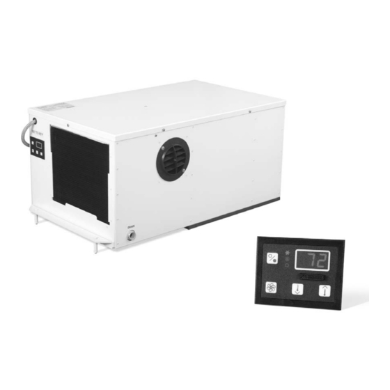
Radome Environmental Control Unit
With Passport I/O Compact Digital Display
I
, O
NSTALLATION
PERATION
Dometic Corporation
Rev. 20170601
L-2283 English
Part Number 297200038
COPYRIGHT © 1997-2017 Dometic Corporation. All Rights Reserved.
No part of this publication may be reproduced, translated, stored in a retrieval system, or transmitted in any form or by any means
electronic, mechanical, photocopying,recording or otherwise without prior written consent by Dometic Corporation. Every precaution
has been taken in the preparation of this manual to insure its accuracy. However, Dometic Corporation assumes no responsibility for
errors and omission. Neither is any liability assumed for damages resulting from the use of this product and information contained
herein.
& M
M
AINTENANCE
ANUAL
Advertisement
Table of Contents

Subscribe to Our Youtube Channel
Related Manuals for Dometic Radome ECU


Summary of Contents for Dometic Radome ECU
- Page 1 Dometic Corporation. Every precaution has been taken in the preparation of this manual to insure its accuracy. However, Dometic Corporation assumes no responsibility for errors and omission. Neither is any liability assumed for damages resulting from the use of this product and information contained...
-
Page 2: Table Of Contents
Table of Contents INTRODUCTION ....... 1 OPERATION ....... . . 10 . -
Page 3: Introduction
Before proceeding, read this manual completely. The Radome ECU is covered under the warranty policy contained in this manual. In the interest of product improvement, specifications and designs herein are subject to change without prior notice. -
Page 4: Notices
This manual contains essential safety information concerning the safe and proper installation, operation, and maintenance of your Radome ECU. It is very important that you read and understand the contents of this manual thoroughly before installing or using the equipment. You should keep this manual on your boat for future reference. -
Page 5: Installation Procedures
NITS If you are installing an internal Radome ECU, select a location in the dome that will not interfere with the antenna. Internal units must be accessible and have a clear area below the dome for condenser openings. There must be adequate space for air flow underneath the dome pedestal. -
Page 6: Fan Indicator
OINT Press the Up or Down button to set the desired room temperature. To view the set point, momentarily press and release the Up or Down button. The Radome ECU set point is 85°F. ENSOR Dome temperature is detected by the air sensor on the face plate. -
Page 7: Odes Of Operation
The fan can be set to run continuously whenever the system is turned on, or it can be set to cycle on and off with the compressor. When “con” is selected, the setting is continuous fan operation. The default setting for the Radome ECU is “con”. -
Page 8: Important Programming Notes To Installer And End User
Program Mode. For further information, refer to “Using Program Mode” on page 6. The Radome ECU is a Cool Only system (it does not have a reversing valve), therefore you must make sure the Cool Only Mode value “1” is set for parameter P-1 (this is the factory default for Radome ECU systems). DO NOT program Automatic Mode for a Cool Only unit. -
Page 9: Programming
P-1: Operating Mode For Radome ECU select “1” for Cool Mode only. If your particular system has the electric heater option installed and heating is desired, set this parameter to “2” for Heat Mode only, or to “0” for Automatic Mode. See “P-15: Reverse-Cycle or Electric Heat”... - Page 10 P-15: Reverse-Cycle or Electric Heat Most Radome ECU systems do not support Heat Mode operation, so this parameter setting should remain at the factory default setting of “nor”. If your particular system has the electric heater option installed, then this parameter should be set to “ELE” for Electric Heater Installed.
- Page 11 Select the number of operating hours until the filter reminder appears. Parameter choices are between 10 (100 hours) and 250 (2500 hours). Dometic recommends that you check the air filter at least every 500 hours of operation. The default setting is off, designated with “00”.
- Page 12 On = Select 4°F to 40°F OPERATION Turn on the A/C circuit breaker. Turn the Radome ECU system on by pressing the Power button. ° Use the Up or Down buttons to set the temperature (set point) to 85 Verify that there is a steady airflow out of the supply-air grille.
- Page 13 Radome Environmental Control Unit TROUBLESHOOTING GUIDELINES TROUBLESHOOTING GUIDELINES Table 3: General Troubleshooting PROBLEM POSSIBLE REASON/SOLUTION System will not start. 1. Air conditioner circuit breaker is off. Turn circuit breaker on at ship’s panel. 2. Digital control is not turned on. Press the Power button. 3.
- Page 14 Check the return-air filter about once a month and clean as necessary. To clean the filter, remove it from the unit, rinse with water, air dry, and reinstall. DIAGRAMS & P IRING RODUCT IAGRAMS Wiring and product diagrams are provided on the following pages for each Radome ECU model. L-2283 ENGLISH...
- Page 15 Radome Environmental Control Unit DIAGRAMS Figure 2: HSA 16K-C/CZ/CZ50 Self-Contained Wiring Diagram (for units shipped after August 1, 2009) L-2283 ENGLISH...
- Page 16 DIAGRAMS Radome Environmental Control Unit Figure 3: HSA 16K-C/CZ/CZ50 Self-Contained Wiring Diagram (for units shipped prior to August 1, 2009) L-2283 ENGLISH...
- Page 17 Radome Environmental Control Unit DIAGRAMS Figure 4: HSA 16K-C/CZ/CZ50 Self-Contained Product Diagram L-2283 ENGLISH...
- Page 18 DIAGRAMS Radome Environmental Control Unit EMPLATE NTERIOR Figure 5: Mounting Template For Interior Self-Contained System L-2283 ENGLISH...
- Page 19 Radome Environmental Control Unit DIAGRAMS OUNTING IAGRAMS Figure 6: Mounting Diagram For Self-Contained System L-2283 ENGLISH...
- Page 20 DIAGRAMS Radome Environmental Control Unit Figure 7: Mounting Diagram For System With Existing Hatchway Covers L-2283 ENGLISH...
- Page 21 NOTES...
- Page 22 NOTES...
- Page 23 NOTES...
- Page 24 DOMETIC MARINE DIVISION 2000 N. Andrews Ave. Pompano Beach, FL 33069 USA +1 954-973-2477 +1 954-979-4414 Email MarineSales@dometic.com 24/7 TECH SUPPORT FOR UNITED STATES AND CANADA 8:00 AM to 5:00 PM Eastern Time: +1 800-542-2477 After hours and weekends: +1 888-440-4494...
Need help?
Do you have a question about the Radome ECU and is the answer not in the manual?
Questions and answers