
Related Manuals for Dometic Elite Control Series


Summary of Contents for Dometic Elite Control Series
- Page 1 MARINE CONTROL UNITS Elite Control Series Elite Control Installation and Operating Manual ..2 WARNING Cancer and Reproductive Harm www.P65Warnings.ca.gov L-5507 | Form No. 341204 20200325 | ©2020 Dometic Corporation...
-
Page 2: Table Of Contents
8 Troubleshooting . . . . . . . . . . . . . . . . . . . . . . . 25 Visit: www.dometic.com 9 Disposal . -
Page 3: Supplemental Directives
• Use for purposes other than those described in the – ANSI/NFPA70, National Electrical Code (NEC) operating manual – American Boat and Yacht Council (ABYC) Dometic Corporation reserves the right to modify appearances and specifications without notice. 1 .4 General Safety Messages WARNING: ELECTRICAL SHOCK, FIRE, AND/ 3 General Information OR EXPLOSION HAZARD . -
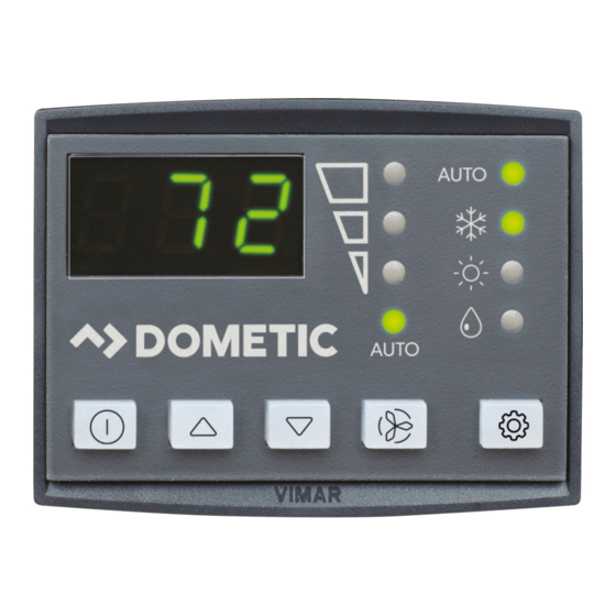
Page 4: Display Features
Specifications Elite Control Additional Parts Indicator Indicator Name Function Required for CW Installations (not included) Displays the inside, set Temperature LED point, outside, and water Water Inlet Temperature Sensor Display temperatures Optional Parts Indicates the fan speed as Outside Air Temperature (OAT) Sensor Fan Speed high, medium, or low Inside Air Temperature Sensor... -
Page 5: Cable Length
Elite Control Specifications 4 .2 Cable Length 4 .4 Operational Specifications Set Point Operating 65 °F to 85 °F (18 °C to 29 °C ) Display Cable Range 15.0 ft (4.6 m) Standard Self-Contained Ambient Temperature 5 °F to 150 °F (-15 °C to 66 °C) Operating Range Inside Air Temperature Displayed... -
Page 6: Wiring Diagrams
Wiring Diagrams Elite Control 5 Wiring Diagrams WARNING: ELECTRIC SHOCK HAZARD . Turn power OFF before performing any electrical installation or maintenance activities. Failure to obey this warning could result in death or serious injury. Figure 2 and Figure 3 provide examples of the DX and CW Wiring for the Elite Control. - Page 7 Elite Control Wiring Diagrams SMX DISPLAYS ONLY For Humidistat For Changeover Switch Display Jacks (for 8- or 6-pin display and cables) 0-10 VDC Optional Inside Temperature Sensor Jack DC Blower Required Water Inlet Temperature Sensor Optional Water-Out Temperature Sensor JP1 System Selection Jumper Optional Outside Air Temperature Sensor JP5 Temperature Sensor Selection Jumper Ground...
-
Page 8: Installation
Installation Elite Control 6 Installation 6 .2 Preparing the Wall Cut the cabin wall to fit the display panel, according to WARNING: ELECTRIC SHOCK HAZARD . the bezel being used. Turn power OFF before performing any electrical installation or maintenance activities. Failure to obey this warning could result in death or serious injury. -
Page 9: Mounting The Display Panel
Elite Control Operation 6 .4 Mounting the Display Panel 6 .5 Testing the Display NOTICE: For DX units only: do not turn the circuit breaker or power supplied to the unit OFF and then immediately turn it back ON. Allow at least five minutes for the refrigerant pressure to equalize. -
Page 10: Understanding The Heating And Cooling
Operation Elite Control 7 .1 Understanding the Heating and To view the current water temperature, press and hold Power and Down. Refer to “Using the Control Display Cooling Cycles Panel” on page 13. The fan remains on low speed until the adequate water temperature is available. The heating and cooling cycles operate differently depending on the system installed. -
Page 11: Choosing The Control Operation
Elite Control Operation 7 .1 .4 Reversing-Valve Operation (DX and by periodic HEAT mode cycles with the fan turned off. Systems Only) The de-icing cycle algorithm initiates periodic compressor shutdowns every 10 minutes if the inside COOL mode or HEAT mode is determined by the temperature is at or below 69 °F (20 °C). - Page 12 Operation Elite Control – Display LEDs illuminate to indicate the selected – To indicate an OFF state, all the display LEDs turn off. mode. – When the display is making a call for heating, – The display locks into the last mode selected after cooling, auxiliary heat, or humidity, the appropriate five seconds of inactivity, then displays the room Mode indicator illuminates (and flashes for auxiliary...
-
Page 13: Using The Control Display Panel
Elite Control Operation Available Fan Modes and Options for Operation – Display LEDs illuminate to indicate the selected Press and release the Fan button to select a fan mode. mode. Refer to “Available Modes and Options for Operation” on page 12. Indicator Description/Mode Function... -
Page 14: Programming The Control
Operation Elite Control Button Combinations Button Names Function Display the outdoor temperature: Press simultaneously and hold. Up & Down The display shows the outdoor temperature reading while this combination is held. & (CW only) Power & Down Display the chilled-water-inlet temperature: Press simultaneously and hold. &... - Page 15 Elite Control Operation – Once this parameter is set, the only allowable modes are OFF, COOL, AUXILIARY HEAT, and DEHUMIDIFICATION. – If the AUTOMATIC mode is selected and the thermostat calls for heat, the compressor will run. Since there is no reversing valve, the air conditioning unit will supply cool air when heating is desired.
- Page 16 Operation Elite Control 7 .4 .2 Selecting a Parameter The following table describes the parameters available for the Elite Control. Parameter Name Factory Default Parameter Range 51–95 Select a higher number to increase the fan speed, a lower number to decrease the fan speed. High Fan Limit The 35-95 parameter range setting is applicable to software revision #B24 and newer.
- Page 17 Elite Control Operation Parameter Name Factory Default Parameter Range 1 = ON with 5 °F (3 °C) Display Sensor Differential 2 = ON with 7 °F (4 °C) Display Sensor Differential Select the parameter setting for the de-icing feature depending on whether you are using the display built-in temperature sensor or the optional inside air temperature sensor.
- Page 18 When programmed for auxiliary electric heat, both the electric-heater relay and the valve relay are energized. This change supports newer circuit board revisions without the electric-heat relay. Please consult with Dometic Customer Service or with an authorized service technician for P-13 Auxiliary Heat Enable assistance.
- Page 19 • Press the Down button to reset the value to 0, restart the timer, and clear the reminder. This setting is applicable to software revision #A15 and newer. Dometic recommends checking the air filter at least every 500 hours of operation. Displays the elapsed time (in hours x10) since the timer was started or reset.
- Page 20 Operation Elite Control Parameter Name Factory Default Parameter Range 1 = 1 °F (.6 °C) Differential 2 = 2 °F (1 °C) Differential Set the temperature differential in Fahrenheit for all modes of operation: AUTOMATIC, COOL, HEAT, or AUXILIARY HEAT. Refer to “Choosing the Control Operation” on page 11. Set Point Temperature P-23 •...
- Page 21 Elite Control Operation Parameter Name Factory Default Parameter Range 50–80 P-28 Enable the optional room temperature/relative humidity combination sensor. This allows the system to dehumidify using auxiliary electric heat (if an auxiliary electric heater is installed and enabled) when the cabin humidity rises above the selected relative humidity (RH).
- Page 22 Operation Elite Control Parameter Name Factory Default Parameter Range HP = heat pump mode CL = cool or (optional) electric heat mode Select heat pump or cool-only operation. • Selecting HP operates the unit in the default heat pump mode, which allows for cooling, reverse cycle heating, or (optional) auxiliary electric heat.
- Page 23 Elite Control Operation Fail Safe Levels Description DX Only Fail Safe Level 0: Temporary failsafe, limited to five-minutes (only in display firmware #C40 and newer). Provides minimal failsafe protection and is not recommended. • The system will automatically switch back to Level 3 after five minutes (for display firmware #C40 and newer.
-
Page 24: Navigation Tree
Operation Elite Control 7 .5 Navigation Tree This section shows the menu navigation for the Elite Control. FAN MODES DISPLAY ICONS OPERATING MODES Fan Mode Fan Modes Manual Fan Mode Cool Mode Mode Operating Modes Fan-Only Mode Heat Mode Mode+Down Fault Log Cycled/Continuous Fan Mode Dehumidification Mode... -
Page 25: Troubleshooting
Elite Control Troubleshooting 8 Troubleshooting The following table describes some common occurrences that are not a result of defective workmanship or materials. Problem Possible Causes Recommended Solution The system does Turn on the air conditioning unit circuit breaker at the ship’s panel. The air conditioning unit circuit breaker is off. - Page 26 Troubleshooting Elite Control Problem Possible Causes Recommended Solution The condenser • Shut down the system to prevent damage to the condenser. The seawater temperature is below 40 °F coil is iced while in (4 °C). • Allow the coil to defrost. HEAT mode. The fan does Change the fan operation to continuous fan operation or fan cycling with The digital control is set for either fan cycling...
- Page 27 Elite Control Troubleshooting Problem Possible Causes Recommended Solution The pump does • Call service to verify if a relay on the circuit board is shorted or if the The circuit board is shorted. not shut off. pump relay board is defective, if applicable. •...
- Page 28 Troubleshooting Elite Control Problem Possible Causes Recommended Solution A high pressure • Water should be flowing strongly out of the overflow. Be sure the The seawater flow is obstructed. The fault is present. seacock is open and water is flowing to the pump. condenser coil may be too hot to touch.
- Page 29 Elite Control Troubleshooting Problem Possible Causes Recommended Solution The air Perform a factory reset of the display: The display is experiencing a power conditioning unit interruption, voltage frequency fluctuation, 1. Turn the power off. does not respond electromagnetic interference from other 2.
-
Page 30: Disposal
10 Warranty Information LIMITED WARRANTY AVAILABLE AT WWW.DOMETIC. COM/WARRANTY. IF YOU HAVE QUESTIONS, OR TO OBTAIN A COPY OF THE LIMITED WARRANTY FREE OF CHARGE,... - Page 31 Elite Control...
- Page 32 YOUR LOCAL YOUR LOCAL DEALER SUPPORT SALES OFFICE dometic .com/dealer dometic .com/contact dometic .com/sales-offices A complete list of Dometic companies, which comprise the Dometic Group, can be found in the public filings of: DOMETIC GROUP AB Hemvärnsgatan 15 SE-17154 Solna Sweden...
Need help?
Do you have a question about the Elite Control Series and is the answer not in the manual?
Questions and answers