Table of Contents
Advertisement
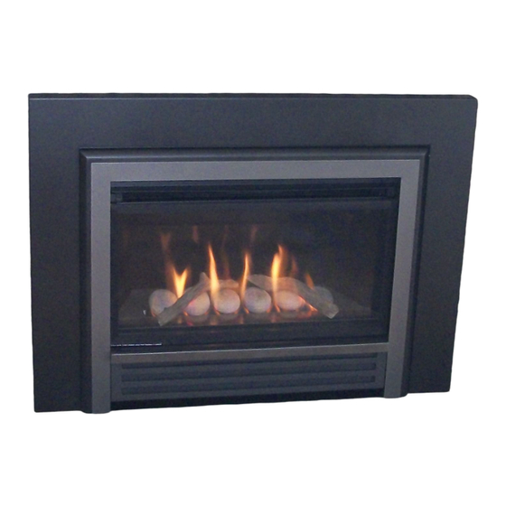
739ILN/P (Logs) & 739IRN/P (Rocks)
Installation and Owner's Manual
WARNING: If the information in these
instructions is not followed exactly, a fi re
or explosion may result causing property
damage, personal injury or loss of life.
Do not store or use gasoline or other
fl ammable vapors and liquids in the vicinity
of this or any other appliance.
WHAT TO DO IF YOU SMELL GAS
• Do not try to light the appliance.
• Do not touch any electrical switch; do not
use any phone in your building.
• Immediately call your gas supplier from
a neighbor's phone. Follow the gas
supplier's instructions.
• If you cannot reach your gas supplier, call
the fi re department.
Installation and service must be performed
by a qualifi ed installer, service agency or the
gas supplier.
4001514-12
©2012, Miles Industries Ltd.
L
EGEND
DV Gas Insert
HOT GLASS WILL
CAUSE BURNS.
DO NOT TOUCH GLASS
UNTIL COOLED.
NEVER ALLOW CHILDREN
TO TOUCH GLASS.
Manufactured by
MILES INDUSTRIES LTD., British Columbia, Canada
www.valorfi replaces.com
IN STA LLER
Leav e t his manua l
with the applia nce .
C ON SU MER
Ret ain this ma nual
for f uture r efe re nce.
Please read this manual BEFORE installing
and operating this appliance.
This appliance may be installed in an
after-market permanently located,
manufactured (mobile) home where not
prohibited by local codes.
This appliance is only for use with the type
of gas indicated on the rating plate. This
appliance is not convertible for use with
other gases, unless a certifi ed kit is used.
This appliance is a domestic room-heating
appliance. It must not be used for any other
purposes such as drying clothes, etc.
This appliance is suitable for installation in a
bedroom or bed sitting room.
Massachusetts: The piping and fi nal
gas connection must be performed by a
licensed plumber or gas fi tter in the State of
Massachusetts.
Ce guide est disponible en français sur demande.
Advertisement
Table of Contents

Related Manuals for Valor LEGEND 739ILN


Summary of Contents for Valor LEGEND 739ILN
- Page 1 EGEND DV Gas Insert 739ILN/P (Logs) & 739IRN/P (Rocks) Installation and Owner’s Manual IN STA LLER Leav e t his manua l HOT GLASS WILL with the applia nce . CAUSE BURNS. DO NOT TOUCH GLASS C ON SU MER UNTIL COOLED.
-
Page 2: Table Of Contents
Designed and Manufactured by / for Miles Industries Ltd. 190–2255 Dollarton Highway, North Vancouver, BC, CANADA V7H 3B1 Tel. 604-984-3496 Fax 604-984-0246 www.valorfi replaces.com © Copyright Miles Industries Ltd., 2012... -
Page 3: Safety Precautions
Safety Precautions READ and UNDERSTAND all instructions carefully This unit MUST be used with a vent system as before starting the installation. FAILURE TO FOLLOW described in this installation manual. NO OTHER vent these installation instructions may result in possible fi re system or components MAY BE USED. -
Page 4: Safety And Your Fireplace
Child Safety Precautions and Recommendations, • A physical barrier is strongly recommended if there are young Parts of your Valor Fireplace become • children, or at-risk individuals in the extremely hot while in operation. house. Install an approved after- The glass viewing window •... -
Page 5: Owner's Information
For purchasing a Valor by Miles Industries. Your new EXTREMELY HOT!!! radiant gas heater is a technical appliance that must be installed by a qualifi ed dealer. Each Valor fi replace • READ the SAFETY information on pages is fully tested during the production process for your 3 and 4 of this manual BEFORE operating safety and comfort. - Page 6 OWNER’S Owner’s Information INFORMATION 2. Gently pull the bottom of the window outward and Cleaning unhook it from the fi rebox’s opening frame. WARNING WARNING 3. Set the window aside in a safe place to avoid damage. DO NOT TOUCH THE GLASS WHILE IT IS HOT! DO NOT TOUCH THE GLASS WHILE IT IS HOT! To refi...
- Page 7 OWNER’S Owner’s Information INFORMATION Checks Remote Control Handset Wall A periodic check of the pilot and burner fl ames should Holder be made. Check after the fi re has been on for at least Your fi replace equipment includes a wall 30 minutes.
- Page 8 OWNER’S Owner’s Information INFORMATION (including pilot) Servicing How to Turn Your Fireplace OFF If any attention is required for your appliance, contact Familiarize yourself with each of these methods before your supplier quoting the model number. It will be helpful operating your fi...
-
Page 9: Remote Control Operation
OWNER’S Remote Control Operation INFORMATION NOTE: Before using the remote control system for IMPORTANT: BEFORE YOU BEGIN, please note that the fi rst time, the receiver and the handset must be on this system, the settings of time, temperature and synchronized. - Page 10 OWNER’S Remote Control Operation INFORMATION • Press and hold (small fl ame) MODES OF OPERATION button to decrease fl ame height or • Briefl y pressing the SET button to set the appliance at pilot fl ame. changes the mode of operation in •...
- Page 11 OWNER’S Remote Control Operation INFORMATION SETTING THE ON / OFF TEMPERATURES SETTING THE “NIGHTTIME SETBACK” SETTING THE “DAYTIME” TEMPERATURE TEMPERATURE (sun), 23ºC / 74ºF (moon), “ Default Settings: Default Settings: ” (OFF) TEMP T E M P • Briefl y press SET button to scroll to •...
- Page 12 OWNER’S Remote Control Operation INFORMATION SETTING P1 OFF TIME SETTING PROGRAM TIMERS • You can program two periods of time between 12:00 • Briefl y press SET button to scroll am and 11:50 pm in each 24-hour cycle. to TIMER (moon) while the •...
-
Page 13: Options
OWNER’S Remote Control Operation INFORMATION Timer Programming Example (default temperatures shown) 4:00 p.m.— 6:00 a.m.— 8:00 a.m.— 10:00 p.m.— ☼ 6:00 a.m.— ☼ ☼ ☽ ☽ Start time Start time End time End time Start time ☼ ☼ ☽ ☽ Set temp 40˚F Set temp... -
Page 14: Lighting Instructions
OWNER’S Lighting Instructions INFORMATION FOR YOUR SAFETY, READ BEFORE LIGHTING WARNING : If you do not follow these instructions exactly A. This appliance has a pilot which must be lighted by hand or by remote control. Follow these instructions exactly. To save gas, turn the pilot off when not using the appliance for a prolonged period of time. -
Page 15: Specifi Cations
Installation Code CAN/CGA-B149. Only qualifi ed Supply Gas licensed or trained personnel should install this appliance. Heater engine 739IRN and 739ILN are used with natural gas. This appliance must be electrically grounded in Heater engine 739IRP and 739ILP are used with accordance with local codes, or, in the absence of local propane gas. -
Page 16: Overview
QUALIFIED Overview INSTALLER This appliance may ONLY be installed in an existing unaltered, functioning solid-fuel burning fi replace with a working fl ue and constructed of non-combustible material. DO NOT install into combustible construction. This appliance is NOT APPROVED for installation with a zero clearance kit. WARNING WARNING Chimney Terminal Cap... -
Page 17: Dimensions
QUALIFIED Dimensions INSTALLER 28-5/8” (727 mm) 19-1/2” (495 mm) 12” (305 mm) or 12-5/8” (321 mm) Varies with outer trim options Optional Outer Trim or Surround sold separately 9-3/8” (238 mm) or 10” (254 mm) Varies with outer trim options 20”... -
Page 18: Clearances
QUALIFIED Clearances INSTALLER WARNING WARNING Some materials or items, although safe, may discolor, shrink, warp, crack, peel, Some materials or items, although safe, may discolor, shrink, warp, crack, peel, and so on because of the heat produced by the fi replace. Avoid placing candles, and so on because of the heat produced by the fi... -
Page 19: Venting
QUALIFIED Venting INSTALLER Typical Vent Installation See list of approved Venting Accessories on page 32 of this manual. Vent Location The vent terminal must be located through the roof. This direct Terminal Cap vent appliance is designed to operate when an undisturbed airfl... -
Page 20: Installation Planning
QUALIFIED Installation Planning INSTALLER Only qualifi ed licensed or trained personnel should install this appliance. Installer—READ THIS FIRST 12. Put batteries in receiver and remote control 1. YOU NEED TO KNOW FROM THE handset. HOMEOWNER what accessories (surround, door, etc.) will be installed with this fi replace; 13. -
Page 21: Appliance Preparation
QUALIFIED Existing Fireplace Preparation INSTALLER Gas Line Routing Combustible Mantels Plan the routing of the gas line before proceeding. Combustible mantel clearances must conform to those Utilize the existing hole for the gas line. If the factory- required for the original solid-fuel fi replace into which built fi... - Page 22 QUALIFIED Appliance Preparation INSTALLER Window Removal The window is held in place by four spring-loaded bolts, two at the top and two at the bottom. 1. To remove the window, turn each bolt a quarter turn to disengage the bolt pin. 2.
- Page 23 QUALIFIED Appliance Preparation INSTALLER Venting Installation IMPORTANT: This appliance’s venting system is room sealed and therefore, does not require room air to be used in the combustion process. 1. Rough-in two 3” diameter vent liners into the existing chimney system from the roof. Be careful not to tear or damage the liners in the process.
-
Page 24: Supply Gas Installation
QUALIFIED Supply Gas Installation INSTALLER The gas supply inlet connection is a 3/8” NPT female Pressure Test Points connector and is located on the left hand side of the The minimum supply pressure is given in the section control valve. Specifi... -
Page 25: Panels Installation
QUALIFIED Panels Installation INSTALLER The following guidelines apply for all liners. 4. Rotate the anchor up and out of the way and slide the right hand side panel against the fi rebox side. 1. Inside the fi rebox, on the top of each side, release The panel should be parallel to the edge of the the screw of the side brick anchors (one per side) burner plate. -
Page 26: Ceramic Logs Installation (739Il)
QUALIFIED Ceramic Logs Installation (739IL) INSTALLER Unpack the ceramic logs very carefully to avoid damaging the fragile material. Install the logs as shown below. Please note that the position of the logs is critical to ensure proper performance of the appliance. 1. -
Page 27: Ceramic Rocks Installation (739Ir)
QUALIFIED Ceramic Rocks Installation (739IR) INSTALLER Unpack the ceramic rocks kit very carefully to avoid damaging the fragile material. Install the components as shown below. Please note that the position of the rocks and twigs (if used) is critical to ensure proper performance of the appliance. - Page 28 QUALIFIED Ceramic Rocks Installation (739IR) INSTALLER 4. The underside of each ceramic rock is identifi ed by a number and a specifi c protruding positioning triangle. Rock Install the six rocks from left to right starting identifi cation with rock no. 1. Triangular hole in ceramic...
-
Page 29: Window Refi Tting
QUALIFIED Window Refi tting INSTALLER 1. To refi t the window, place the window against the fi rebox’s opening frame. Make sure that the wider part of the window frame is at the bottom. 2. While you hold it, push in and turn the two bottom spring-loaded bolts a quarter turn to engage their pin. -
Page 30: Operation Check & Aeration Settings Adjustment
QUALIFIED Operation Check & Aeration Settings Adjustment INSTALLER In a few unusual installations, the fl ame picture may Operation Check be improved by adjusting the aeration. The need for Turn the fi replace fl ame up and down using the adjustment should be determined only by operating the remote control to confi... -
Page 31: Wiring Diagram
QUALIFIED Wiring Diagram INSTALLER Optional Wall Switch Kit 1265WSK Connector Yellow GV60 Wiring Diagram... -
Page 32: Approved Venting Components
QUALIFIED Approved Venting Components INSTALLER Approved Direct Vent Suppliers for Valor Models 700, 739, 780, 785 and RF24DV Venting Parts Code / availability by Manufacturer Venting Parts Description 4DVC Standard Co-axial 46DVA-VC 4DT-VC TM-4VT — HSDV4658-1313 — 4DH-1313 High Wind Co-axial 46DVA-VCH —... -
Page 33: Warranty
OWNER’S Warranty INFORMATION If you have a problem with this unit, please contact your dealer or supplier immediately. Under no circumstances should you attempt to service the unit in any way by yourself. The warranties in paragraphs 1 and 2 are provided only to the fi rst purchaser/user of this unit, are not transferable and are subject to the conditions and limitations in paragraphs 3, 4 and 5. -
Page 34: Spare Parts
OWNER’S Spare Parts INFORMATION Part Part Code Description Code Description Number Number Exhaust Slide Assembly 4001133 Module Gasket—Front 4000173 Exhaust Slide Gasket 4000176 Module Gasket—Left 4000181 Fan Closure Plate 4001136 Olive Nut for Pilot Pipe 220K913 Port Cover 4001820 Pipe—Valve to Pilot 4001838 Rock Support (739IR) 4001768... - Page 35 OWNER’S Spare Parts INFORMATION Part Code Description Number Right Fluted Panel (739IR) 4001813 Right Brick Panel (739IL) 4001810 Glass Panel (739IR) 4001836 Front Support—Platform (739IR) 4001835AH Ceramic Platform (739IR) 4001832 Log Set Complete (739IL) 4001696 Rear Log (739IL) 4001697 Front Left Log (739IL) 4001699 Front Right Log (739IL) 4001700...
- Page 36 OWNER’S Spare Parts INFORMATION 12 13 45a, 45b...
- Page 37 Thank You ... For purchasing a Valor by Miles Industries. Your new radiant gas heater is a technical appliance that must be installed by a qualifi ed installer. Please fi ll in the information below. The information provided will be used for customer records only.
- Page 38 Tape Shut Fold here Postage needed Miles Industries Ltd. 190 - 2255 Dollarton Highway North Vancouver, BC V7H 3B1 Canada Online Warranty registration at www.valorfi replaces.com Thank you for choosing a Valor Product...
Need help?
Do you have a question about the LEGEND 739ILN and is the answer not in the manual?
Questions and answers