Valor G3 Installation Manual
Gravity vent insert gas fireplace
Hide thumbs
Also See for G3:
- Installation & owner's manual (48 pages) ,
- Installation manual (9 pages) ,
- Installation instructions manual (6 pages)
Table of Contents
Advertisement
Quick Links
Installation Manual
G3
Installer: Leave this manual with the appliance.
Consumer: Retain this manual for future reference.
WARNING:
FIRE OR EXPLOSION HAZARD
Failure to follow safety warnings
exactly could result in serious
injury, death, or property damage.
Do not store or use gasoline or other
fl ammable vapors and liquids in the
vicinity of this or any other appliance.
WHAT TO DO IF YOU SMELL GAS
Do not try to light any appliance.
▪
DANGER
4007448-09
Gravity Vent Insert Gas Fireplace
natural gas
738KN
propane gas 738KP
Hot glass
will cause burns.
Do not touch glass
until cooled.
Never allow children
to touch glass.
Installer: Place model/serial number here.
Do not touch any electrical switch; do
▪
not use any phone in your building.
Leave the building immediately.
▪
Immediately call your gas supplier from
▪
a neighbor's phone. Follow the gas
supplier's instructions.
If you cannot reach your gas supplier,
▪
call the fi re department.
Installation and service must be
performed by a qualifi ed installer, service
agency or the gas supplier.
A barrier designed to reduce
the risk of burns from the hot
viewing glass is provided with this
appliance and must be installed for
the protection of children and
other at-risk individuals.
Advertisement
Table of Contents

Related Manuals for Valor G3


Summary of Contents for Valor G3
- Page 1 Installation Manual Gravity Vent Insert Gas Fireplace natural gas 738KN propane gas 738KP Installer: Place model/serial number here. Installer: Leave this manual with the appliance. Consumer: Retain this manual for future reference. Do not touch any electrical switch; do ▪ WARNING: not use any phone in your building.
- Page 2 Miles Industries Ltd. grants no warranty, implied or stated, for the installation Valor Fireplaces or maintenance of your heater, and assumes no 190–2255 Dollarton Highway responsibility for any consequential damage(s).
-
Page 3: Table Of Contents
Welcome to Valor ® This appliance has been professionally installed by: Please read this manual BEFORE Dealer Name: ________________________________ installing and operating this Phone:______________________________________ appliance. Fireplace Safety ..........4 Specifi cations ............. 6 Kits and Accessories.......... 7 Dimensions ............8 Clearances ............ -
Page 4: Fireplace Safety
fi replace. Failure to follow these instructions may result in possible fi re hazard and will void the warranty. Replacement manuals are available by contacting the Valor Customer Service at 1-800-468-2567, or by visiting valorfi... - Page 5 Fireplace Safety Glass window Intended use • This appliance is designed and approved as a supple- mental heater and provides the potential for most WARNING energy conservation when used while attended. The Do not operate this appliance with the use of an alternate primary heat source is advisable. glass front removed, cracked, or broken.
-
Page 6: Specifications
Specifications Approval & Codes Supply Gas This appliance is certified to ANSI Z21.88/CSA 2.33 Heater engine 738KN uses natural gas. American National Standard / CSA Standard for Vented Heater engine 738KP uses propane gas. Gas Fireplace Heaters for use in Canada and USA, and The supply pressure must be between the limits shown to CGA 2.17-91 High Altitude Standard in Canada. -
Page 7: Kits And Accessories
739RGL Refl ective Glass Panels Other Accessories 739FBL Fluted Black Panels 770ZCK Zero Clearance Kit 739VRL Valor Red Brick Panels 1265WSK Wall Switch Kit Inner Fronts (choose one) Barrier GV60CKO Outdoor Fireplace Conversion Kit Screen Hearth gates such as Cardinal’s VersaGate... -
Page 8: Dimensions
Dimensions Dimensions 28-5/8” (727 mm) 19-1/2” (495 mm) See table below for minimum cavity dimensions Top View Optional Outer Trim or Surround sold separately 7-7/8” - 9-7/8“ (200 - 251 mm) Varies with outer trim options 20” (508 mm) Gas inlet Gas connection Left Side View Front View... -
Page 9: Clearances
Clearances Mantel and Sidewall Combustible Mantel Clearances Sidewall Clearances sidewall 9” (229 mm) Do not put furniture or objects within 36” (914 mm) of the front of appliance Minimum distance from side of appliance (liner box) to combustible wall: 9” [229 mm]. Mantel legs projecting forward less than 6”... -
Page 10: Installation Planning
Installation Planning Before Installation Caution Only qualified, licensed, or trained personnel should install this appliance. Installer - READ THIS FIRST! 1. YOU NEED TO KNOW FROM THE HOMEOWNER: • What accessories (surround, screen, ZC kit, etc.) will be installed 2. Unpack the appliance, removing all items packed inside and around it. -
Page 11: Concept
Installation Planning Concept This appliance, as supplied, may ONLY be installed in an existing unaltered, functioning solid-fuel burning fireplace with a working flue and constructed of non-combustible material. This appliance may be installed in outdoor, weather-protected environments as defined in the GV60CKO Outdoor Conversion Kit instruction manual. -
Page 12: Venting
Venting Concept Vent Location Typical Vent Installation The vent terminal must be located through the roof. This gravity Terminal Cap vent appliance is designed to operate when an undisturbed airflow hits the outside vent terminal from any direction. Flashing Check local codes for allowable vertical vent termination. Vent Materials Use a 3”... -
Page 13: Preparation
Preparation Existing Fireplace Existing Fireplace Preparation Gas Line Routing A few points must be considered before inserting Plan the routing of the gas line before proceeding. the 738 into an existing fi replace cavity. Generally, no Utilize the existing hole for the gas line of the factory- modifi... -
Page 14: Installation
Installation Window Remove Window The window is held in place by four spring-loaded bolts, two at the top and two at the bottom. 1. To remove the window, turn each bolt a quarter turn to disengage the bolt pin. 2. Gently pull the bottom of the window outward and unhook it from the fi... -
Page 15: Appliance And Venting
Installation Appliance and Venting Connect Venting and Insert Appliance IMPORTANT: This appliance’s venting system require room air to be used in the combustion process. 1. Rough-in one 3” diameter vent liner into the existing chimney system from the roof. Be careful not to tear or damage the liner in the process. -
Page 16: Gas Supply
Installation Gas Supply Connect Gas Supply Pressure Test Points The gas supply inlet connection is a 3/8” NPT female The minimum supply pressure is given in the section connector andis located on the left hand side of the Specifications of this manual— page 6. control valve. -
Page 17: Liners
Installation Liners Liner Installation The following guidelines apply for all liners except the 739RGL Reflective Glass Liners which require some preparation prior to installation—see instructions packed with liners. 1. Inside the fi rebox, on the top of each side, release the screw of the side brick anchors (one per side) just enough to allow them to rotate. -
Page 18: Fuel Bed Support
Installation Fuel Bed Support Adjust Fuel Bed Support (if necessary) The appliance is supplied a the fuel bed support with an adjustable bracket already installed in a specific position. Unless otherwise indicated in the fuel beds’ installation instructions, an adjustment is not necessary.* If desirable, the position of the bracket can be changed by releasing its 3 retaining screws, moving it as required and tightening the screws. -
Page 19: Fuel Beds
Installation Fuel Beds Traditional Log Kit 739TLK Installation Carefully unpack the kit. Note each log has its own Material required number stamped on the bottom. Some logs have pegs • Traditional Log Kit, which contains: to help you place them on the burner platform, or other •... - Page 20 Installation Fuel Beds Logs 3. Place log G31 from pin on G30 to base panel. 1. Place log G30 on the fuel bed support; slide it left against the pilot shield. The front tabs of the sup- port should be in the notches of the log. 4.
- Page 21 Vacuum area after installation. IMPORTANT Approved for use only with the ceramic logs and embers provided with your Valor fireplace. The use of any other products may void your fireplace warranty. 739TLK Installed Base panel...
-
Page 22: Rock Set Kit 739Rsk
Installation Fuel Beds Rock Set Kit 739RSK 2. Place the front support platform just inside the Material required fi replace between the • Rock Set Kit, which contains: burner and the front edge of the fi rebox. Be • 6 rocks careful not to damage •... - Page 23 IMPORTANT Approved for use only with the ceramic rocks and logs provided for your Valor fireplace. The use of any other products may void your fireplace 7. Place the left log from the glass panel to rocks 2 and warranty.
-
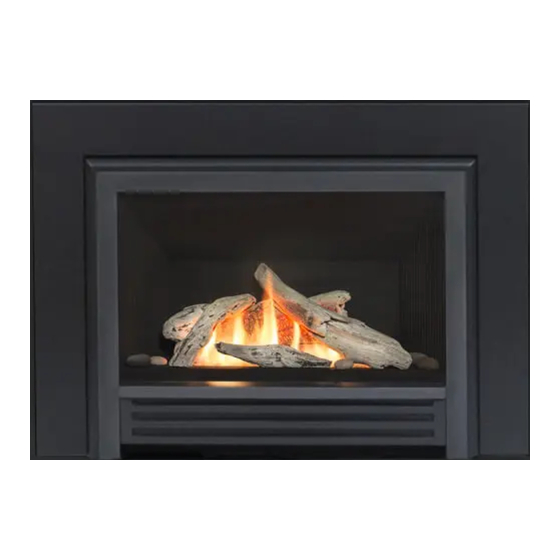
Page 24: Driftwood Kit 739Dwk
Installation Fuel Beds Driftwood Kit 739DWK Logs 1. Identify the base log and place it in the cavity of the Material required ceramic platform. The protruding parts of the log in • Driftwood Kit, which contains: the front should rest against the lip of the fuel bed •... - Page 25 Installation Fuel Beds 3. Place the front log inserting its two pins into the two 5. Identify the left side cross log which has one pin at holes at the front of the platform. The ends of the one end. Insert the pin in the hole at the front left of log should be oriented towards the front as the log the platform and rests the top part of the log into should not hang over the inside edge of the plat-...
-
Page 26: Legend Traditional Logs 739Lsk
Vacuum area after installation. IMPORTANT Approved for use only with the ceramic coal and logs provided for your Valor fireplace. The use of any other products may void your fireplace Pilot area warranty. - Page 27 Installation Fuel Beds 3. Place the front left log on the burner. Slide it to the 5. Locate the top right log on the two pins on the right left against the top left log. The narrow end should side of the rear log. Ensure a tight fi t against the fl at rest in the notch in the rear log.
-
Page 28: Window Re-Installation And Checking
Installation Window Re-Installation and Checking Refi t and Check Window 1. To refit the window, place the window against the firebox’s opening frame. Make sure that the wider part of the window frame is at the bottom, and the “TOP” marker is at the top. -
Page 29: Batteries And Remote Control
Installation Batteries and Remote Control Install Battery Holder Synchronize Remote Control The batteries that power the receiver need to be The receiver and the handset of the remote control installed and placed prior to synchronization and use. system must be initially synchronized before the first use. -
Page 30: Check Operation And Aeration
Installation Check Operation and Aeration Check Operation Air Shutters Turn the fireplace flame up and down using the remote Natural gas control to confirm that the full range of inputs is achieved—see the Remote Control Use from page 34. Close Open Adjust Aeration (if necessary) Light the fire and allow the unit to warm up for 10–15... -
Page 31: Front / Trim
Installation Front / Trim Sides Shrouds The side shouds are required to install the front and trim on the appliance. They are supplied with the appliance. Secure them to the appliance outer case as indicated (2 screws/side). Note that some backing or finishing plates may have to be installed before the side shrouds—see instructions packed with the plates/trim/front for all details. -
Page 32: Wiring Diagram
Wiring Diagram MAN Knob Main Valve Knob Optional 1265WSK Wall Switch Kit Combination Control Valve Interruptor Block Connector Thermocouple Vent Safety Switch yellow Antenna Receiver Battery Holder RESET Button GV60 Wiring Diagram... -
Page 33: Appendix A-Lighting Instructions
Appendix A—Lighting Instructions FOR YOUR SAFETY, READ BEFORE LIGHTING WARNING : If you do not follow these instructions exactly causing property damage, personal injury or loss of life. . To save gas, turn the pilot off when not using the appliance for a prolonged period of time. AT TO DO IF ur building. -
Page 34: Appendix B-Remote Control Operation
Appendix B—Remote Control Operation Initial Pairing Before the remote control can be used with the fireplace, it must be paired. See page 29. Radio Frequency Turn Fireplace ON 315 MHz for USA and Canada. Press buttons until you hear a short beep;... - Page 35 Appendix B—Remote Control Operation Setting ºC/24-hr or ºF/12-hr clock Manual Mode M A N In MAN mode, press and hold Manual ame height adjustment. buttons until temperature / clock display changes from Daytime Temperature Mode TEMP When pilot is lit, room temperature °F / 12-hour °C / 24-hour is measured and compared to set...
- Page 36 Appendix B—Remote Control Operation Setting high / low Temperatures Setting Program Timers Setting “DAYTIME” high temperature. You can program two periods of time between 12 am and 11:50 pm in each 24-hour cycle. Default Settings: 23 °C/74 °F TEMP Programs P1 and P2 must be set in the following order Press SET to scroll to TEMP during a 24-hour cycle:...
- Page 37 Appendix B—Remote Control Operation Setting P2 high and low temperature times. Repeat same steps as Setting P1. When all settings are complete, press to save them. Timer Programming Example (default temperatures shown) 6:00 am 8:00 am 4:00 pm 10:00 pm 6:00 am high temp low temp...
-
Page 38: Appendix C-Spare Parts
Injector Elbow (natural gas) 9730012 Liner Set Complete Injector Elbow (propane gas) 9730007 Fluted Black 739FBL Air Shutter Cover (natural gas) 4002346 Valor Red Brick 739VRL Air Shutter Slider (natural gas) 4002345 Refl ective Glass 739RGL Flashback Shield (propane gas) 3000371 Rear Panel... - Page 39 Appendix C—Spare Parts Part Description Number RH Twig 4001828 Glass Panel 4001836 Front Support—Platform 4001835BY Ceramic Platform 4001832 Driftwood Kit 739DWK Rear Log 4005615 Base Log 4005617 RH Cross Log 4005616 Front Log 4005817 LH Cross Log 4005618 Small Beige Beach Pebble (3) 4003087 Small Grey Beach Pebble 4003086...
- Page 40 Appendix C—Spare Parts Natural gas Propane gas natural propane...
- Page 41 Appendix C—Spare Parts 739DWK—Driftwood Kit Ceramic Panels Glass Panels 739TLK—Traditional Log Kit 739RSK—Rock Kit 739LSK—Legend Traditional Logs...
Need help?
Do you have a question about the G3 and is the answer not in the manual?
Questions and answers