ATEN KE6900 User Manual
Kvm over ip matrix system cckm ke management software
Hide thumbs
Also See for KE6900:
- User manual (250 pages) ,
- User manual (324 pages) ,
- User manual (142 pages)
Table of Contents
Advertisement
Quick Links
Download this manual
See also:
User Manual
Advertisement
Table of Contents

Subscribe to Our Youtube Channel
Related Manuals for ATEN KE6900


Summary of Contents for ATEN KE6900
- Page 1 KVM over IP Matrix System KE6900 / KE6900ST / KE6940 / KE8950 / KE8952 CCKM KE Management Software User Manual www.aten.com...
-
Page 2: Emc Information
KVM over IP Matrix System User Manual EMC Information FEDERAL COMMUNICATIONS COMMISSION INTERFERENCE STATEMENT: This equipment has been tested and found to comply with the limits for a Class A digital device, pursuant to Part 15 of the FCC Rules. These limits are designed to provide reasonable protection against harmful interference when the equipment is operated in a commercial environment. -
Page 3: User Information
86-400-810-0-810 Japan 81-3-5615-5811 Korea 82-2-467-6789 North America 1-888-999-ATEN ext 4988 United Kingdom 44-8-4481-58923 User Notice All information, documentation, and specifications contained in this manual are subject to change without prior notification by the manufacturer. The manufacturer makes no representations or warranties, either expressed or implied, with respect to the contents hereof and specifically disclaims any warranties as to merchantability or fitness for any particular purpose. -
Page 4: Package Contents
KVM over IP Matrix System User Manual Package Contents KE6900 / KE6940 The KE6900 / KE6940 package consists of: 1 KE6900T / KE6940T KVM over IP Transmitter 1 KE6900R / KE6940R KVM over IP Receiver 1 USB DVI-D KVM Cable (KE6900T/KE6940T only) 1 DVI-D Cable 1.8 m (KE6940T only) -
Page 5: User Instructions
Read this manual thoroughly and follow the installation and operation procedures carefully to prevent any damage to the KE6900 / KE6900ST / KE6940 / KE8950 / KE8952 or to any other devices on the installation. -
Page 6: Table Of Contents
KE6900 / KE6940 ........ - Page 7 KE6900 LAN Installation ........
- Page 8 KVM over IP Matrix System User Manual Chapter 4. Software Installation Overview..........74 Download - Trial Version .
- Page 9 KVM over IP Matrix System User Manual Assigning Device Permissions ......118 Profile .
- Page 10 KVM over IP Matrix System User Manual Configuring the Serial Port ....... . 154 Device/Profile Commands.
- Page 11 KVM over IP Matrix System User Manual Other Factors........207 Choose a High Performance Switch .
-
Page 12: About This Manual
Chapter 3, OSD Operation, explains the fundamental concepts involved in operating the KE6900 / KE6900ST / KE6940 / KE8950 / KE8952, and provides a complete description of the On Screen Displays (OSDs) and how to work with them. - Page 13 KVM over IP Matrix System User Manual Chapter 12, CLI Commands, provides a complete list of the serial protocol and TCP/IP commands used when utilizing the RS-232 Serial Port or a network connection to configure the KE devices. An Appendix, at the end of the manual provides technical and troubleshooting information.
-
Page 14: Conventions
For information about all ATEN products and how they can help you connect without limits, visit ATEN on the Web or contact an ATEN Authorized Reseller. Visit ATEN on the Web for a list of locations and telephone numbers: International http://www.aten.com... -
Page 15: Chapter 1 Introduction
- away from the keyboard, mouse and display. The KE6900 is a single view extender that supports one DVI display at each end. The KE6940 is a dual view extender that supports two DVI displays at each end, allowing the video output to display across two monitors. - Page 16 Note: The SFP module is sold separately. You can choose the 2A-136G, a multi-mode SFP module that provides 1 GbE connectivity up to 550 meters; or the 2A-137G, a single-mode SFP module that provides 1 GbE connectivity up to 10 kilometers. Visit ATEN's website or contact your ATEN dealer for more information.
-
Page 17: Features
Chapter 1. Introduction Features Remote KVM console access of computers over LAN or Ethernet cable connection Dual console operation – control your system from both the Transmitter and Receiver by USB keyboard, monitor, and mouse RS-232 serial ports allows you to connect to a serial terminal for configuration, and serial devices such as touchscreens and barcode scanners Superior video quality –... -
Page 18: Supported Video Resolutions
KVM over IP Matrix System User Manual 2. The KE Management web GUI can be updated from the CCKM page on our website: www.aten.com. To obtain a license for the full version of the software please contact your ATEN dealer. -
Page 19: Requirements
Chapter 1. Introduction Requirements Console (KE6900) One DVI compatible monitor capable of the highest possible resolution (KE6940) Two DVI compatible monitors capable of the highest possible resolution (KE8950/KE8952) One HDMI compatible monitor capable of the highest possible resolution A USB mouse... - Page 20 KVM over IP Matrix System User Manual Operating System Requirements: Windows 2000, XP, Vista, 2003, 2008, 7 and 8.1 Linux (Ubuntu, CentOS, Fedora, SUSE)
-
Page 21: Operating Systems
Chapter 1. Introduction Operating Systems The KE Series supports the following operating systems which can display standard HDMI/DVI/VGA signals: Version Windows 2000 and higher Linux RedHat 6.0 and higher SUSE 8.2 and higher Mandriva (Mandrake) 9.0 and higher UNIX 4.3 and higher FreeBSD 3.51 and higher Solaris 8 and higher... -
Page 22: Components
KVM over IP Matrix System User Manual Components KE6900T (Transmitter) Front View Component Description Audio Ports These mini stereo ports are for the speakers (green) and microphone (pink). KVM Ports The USB KVM cable supplied with the package that links the Transmitter to the computer plugs into these ports. -
Page 23: Ke6900T (Transmitter) Rear View
Chapter 1. Introduction KE6900T (Transmitter) Rear View Component Description Grounding Terminal The wire used to ground the unit connects here. Reset This switch must be pushed with a thin object, such as the end of a paper clip. Press and release to reboot the device. Power off, hold reset then power on the device while pressing reset to recover from a firmware upgrade failure. - Page 24 KVM over IP Matrix System User Manual Component Description DVI-I Output The cable from the local DVI monitor plugs in here.
-
Page 25: Ke6900R (Receiver) Front View
Chapter 1. Introduction KE6900R (Receiver) Front View POWER REMOTE LOCAL Graphics Video Component Description Power LED Lights blue to indicate the unit is turned on. LAN LED This LED indicates the network status. Lights when connected to the LAN and blinks when the Ethernet connection is active: Orange: 10 Mbps Orange + Green: 100 Mbps... -
Page 26: Ke6900R (Receiver) Rear View
KVM over IP Matrix System User Manual KE6900R (Receiver) Rear View Component Description Grounding The wire used to ground the unit connects here. Terminal Reset This switch must be pushed with a thin object, such as the end of a paper clip. Press and release to reboot the device. -
Page 27: Ke6940T (Transmitter) Front View
Chapter 1. Introduction KE6940T (Transmitter) Front View Component Description Audio Ports These mini stereo ports are for the speakers (green) and microphone (pink). KVM Ports The USB KVM cable supplied with the package that links the Transmitter to the computer plugs into these ports. -
Page 28: Ke6940T (Transmitter) Rear View
KVM over IP Matrix System User Manual KE6940T (Transmitter) Rear View Component Description Grounding Terminal The wire used to ground the unit connects here. Reset This switch must be pushed with a thin object, such as the end of a paper clip. Press and release to reboot the device. - Page 29 Chapter 1. Introduction Component Description DVI-I Output The cable from the local DVI monitor plugs in here.
-
Page 30: Ke6940R (Receiver) Front View
KVM over IP Matrix System User Manual KE6940R (Receiver) Front View POWER REMOTE LOCAL Graphics Video Component Description Power LED Lights blue to indicate the unit is turned on. LAN LED This LED indicates the network status. Lights when connected to the LAN and blinks when the Ethernet connection is active: Orange: 10 Mbps Orange + Green: 100 Mbps... -
Page 31: Ke6940R (Receiver) Rear View
Chapter 1. Introduction KE6940R (Receiver) Rear View Component Description Grounding The wire used to ground the unit connects here. Terminal Reset This switch must be pushed with a thin object, such as the end of a paper clip. Press and release to reboot the device. Power off, hold reset then power on the device while pressing reset to recover from a firmware upgrade failure. -
Page 32: Ke6900St (Transmitter) Front, Rear And Top View
KVM over IP Matrix System User Manual KE6900ST (Transmitter) Front, Rear and Top View Front View Top View Rear View Component Description Reset This switch must be pushed with a thin object, such as the end of a paper clip. Press and release to reboot the device. - Page 33 Chapter 1. Introduction Component Description LAN LED This LED indicates the network status. Lights when connected to the LAN and blinks when the Ethernet connection is active: Orange: 10 Mbps Orange + Green: 100 Mbps Green: 1000 Mbps Off when not connected to the LAN. Power LED Lights blue to indicate the unit is turned on.
-
Page 34: Ke8950T / Ke8952T (Transmitter) Front View
KVM over IP Matrix System User Manual KE8950T / KE8952T (Transmitter) Front View Component Description Audio Ports These mini stereo ports are for the speakers (green) and microphone (pink). KVM Ports The USB KVM cable supplied with the package that links the Transmitter to the computer plugs into these ports. -
Page 35: Ke8950T / Ke8952T (Transmitter) Rear View
Chapter 1. Introduction KE8950T / KE8952T (Transmitter) Rear View Component Description Grounding Terminal The wire used to ground the unit connects here. Reset This switch must be pushed with a thin object, such as the end of a paper clip. Press and release to reboot the device. - Page 36 KVM over IP Matrix System User Manual Component Description SFP Port The Gigabit Ethernet (GbE) optical fiber cable that connects the unit to the LAN plugs in here. HDMI Output The cable from the local HDMI monitor plugs in here.
-
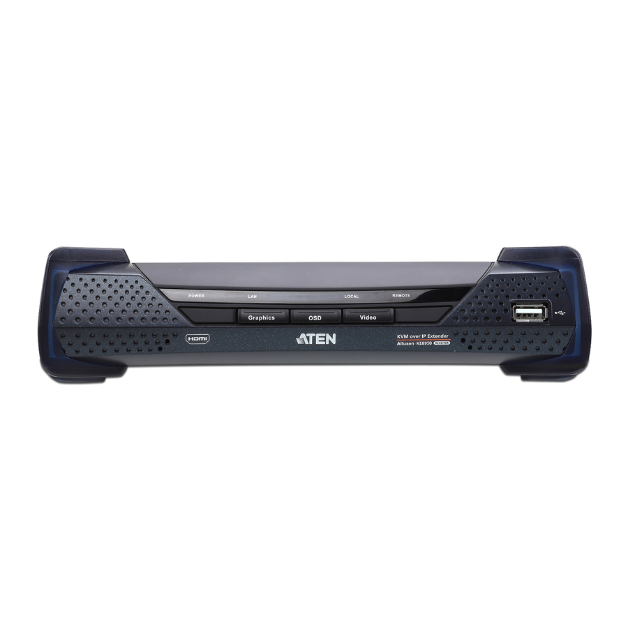
Page 37: Ke8950R / Ke8952R (Receiver) Front View
Chapter 1. Introduction KE8950R / KE8952R (Receiver) Front View POWER REMOTE LOCAL Graphics Video Component Description Power LED Lights blue to indicate the unit is turned on. LAN LED This LED indicates the network status. Lights when connected to the LAN and blinks when the Ethernet connection is active: Orange: 10 Mbps Orange + Green: 100 Mbps... -
Page 38: Ke8950R / Ke8952R (Receiver) Rear View
KVM over IP Matrix System User Manual KE8950R / KE8952R (Receiver) Rear View Component Description Grounding The wire used to ground the unit connects here. Terminal Reset This switch must be pushed with a thin object, such as the end of a paper clip. Press and release to reboot the device. - Page 39 Chapter 1. Introduction Component Description HDMI Output The cable from the local HDMI monitor plugs in here.
-
Page 40: Chapter 2. Hardware Setup
Chapter 2 Hardware Setup 1. Important safety information regarding the placement of this device is found on page 186. Please review it before proceeding. 2. Make sure that the power to all devices connected to the installation is turned off. You must unplug the power cords of any computers that have the Keyboard Power On function. - Page 41 Chapter 2. Hardware Setup 2. Screw the bracket into a convenient location on the rack. Note: These screws are not provided. We recommend that you use M5 x 12 Phillips Type I cross recessed type screws.
-
Page 42: Ke6900St
KVM over IP Matrix System User Manual KE6900ST 1. Using the screws provided in the Mounting Kit, screw the mounting bracket into the bottom of the Transmitter as show below: Phillips hex head M3 x 8 2. Screw the bracket into a convenient location on the rack. Note: These screws are not provided. -
Page 43: Wall Mounting
Chapter 2. Hardware Setup Wall Mounting For convenience the Transmitter can be mounted to a wall. KE6900T/KE6940T 1. Using the screws provided in the Mounting Kit, screw the mounting bracket into the bottom of the Transmitter as show below: Phillips hex head M3 x 8 2. -
Page 44: Ke6900St
KVM over IP Matrix System User Manual KE6900ST 1. Using the screws provided in the Mounting Kit, screw the mounting bracket into the bottom of the Transmitter as show below: Phillips hex head M3 x 8 2. Use the center hole to screw the bracket to a secure wall surface. -
Page 45: Ke6900 Point-To-Point Installation
Chapter 2. Hardware Setup KE6900 Point-to-Point Installation Setting up the KE6900 / KE6940 system in a point-to-point configuration is simply a matter of plugging in the cables. Note: In a point-to-point configuration, no administrator setup is necessary. Make sure that all the equipment is powered off. Refer to the installation diagrams on the next two pages and do the following: 1. -
Page 46: Ke6900 Point-To-Point Installation 1 Of 2
KVM over IP Matrix System User Manual KE6900 Point-to-Point Installation 1 of 2 Cat 5e/6 cable KE6900T Cat 5e/6 cable KE6900R Note: The diagram above shows the KE6900T and KE6900R. The KE6940 installation is the same except that an additional DVI monitor can be... -
Page 47: Ke6900 Point-To-Point Installation 2 Of 2
Chapter 2. Hardware Setup KE6900 Point-to-Point Installation 2 of 2 KE6900T Local PC USB KVM cable Note: The serial port on the Transmitter (shown above) connects to the computer; the serial port on the Receiver (not shown) connects to a... -
Page 48: Ke8950 Point-To-Point Installation
9. Plug the second power adapter into an AC source; then plug the other end into the KE8950R / KE8952R's power jack.* 10. Power on the computer. Note: Power adapters are not provided with KE8952 units. Please contact your ATEN dealer to purchase additional power adapters. -
Page 49: Ke8950 Point-To-Point Installation 1 Of 2
Optical Fiber Cable KE8950R (Rear) DC 5V Note: Power adapters are not provided with the KE8952. Please contact your ATEN dealer to purchase additional power adapters, or use the Power over Ethernet (PoE) feature to supply power to the KE8952. -
Page 50: Ke8950 Point-To-Point Installation 2 Of 2
KVM over IP Matrix System User Manual KE8950 Point-to-Point Installation 2 of 2 KE8950T (Front) Local PC USB HDMI KVM Cable Note: The serial port on the Transmitter (shown above) connects to the computer; the serial port on the Receiver (not shown) connects to a serial device (optional). -
Page 51: Ke6900St Point-To-Point Installation
KE69x0 devices on the same TCP/IP LAN. To setup a LAN installation, simply connect the Cat 5e/6 cable (in step 5 above) to the network instead of directly between two KE69x0 devices and see KE6900 LAN Installation, page 39 for details. - Page 52 KVM over IP Matrix System User Manual Cat 5e/5 cable KE6900ST (Front) KE6900ST (Rear) Local PC USB KVM cable KE6900R...
-
Page 53: Ke6900 Lan Installation
Setting up the units on a network allows point-to-point, point-to-multipoint, and multipoint-to-multipoint computer to console operation by connecting multiple KE6900 / KE6900ST / KE6940 devices on the same TCP/IP LAN. Prior to setup we recommended laying out the plans for your KE installation using our performance guide (see Keys to Network Performance, page 207). - Page 54 KVM over IP Matrix System User Manual 4. For control of serial devices, connect the RS-232 serial port on the Transmitter to a serial port on the computer. 5. Use a Cat 5e/6 cable to connect the KE6900T / KE6940T’s LAN port to the local area TCP/IP network.
-
Page 55: Ke6900 Network Installation Diagram 1 Of 2
Chapter 2. Hardware Setup KE6900 Network Installation Diagram 1 of 2 Cat 5e/6 cable KE6900T TCP/IP Cat 5e/6 cable KE6900R Note: The diagram above shows the KE6900T and KE6900R. The KE6940 installation is the same except that an additional DVI monitor can be... -
Page 56: Ke6900 Network Installation Diagram 2 Of 2
KVM over IP Matrix System User Manual KE6900 Network Installation Diagram 2 of 2 KE6900T Local PC USB KVM cable Note: The serial port on the Transmitter (shown above) connects to the computer; the serial port on the Receiver (not shown) connects to a... -
Page 57: Ke8950 Lan Installation
Chapter 2. Hardware Setup KE8950 LAN Installation Setting up the units on a network allows point-to-point, point-to-multipoint, and multipoint-to-multipoint computer to console operation by connecting multiple KE8950 / KE8952 devices on the same TCP/IP LAN. Prior to setup we recommended laying out the plans for your KE installation using our performance guide (see Keys to Network Performance, page 207). - Page 58 PoE network switch. 2. Power adapters are not provided with KE8952 units. Please contact your ATEN dealer to purchase additional power adapters, or use the Power over Ethernet (PoE) feature to supply power to KE8952 units. 3. A keyboard or mouse with special functions may need to use the USB...
-
Page 59: Ke8950 Network Installation Diagram 1 Of 2
Optical Fiber Cable KE8950R (Rear) DC 5V Note: Power adapters are not provided with KE8952 units. Please contact your ATEN dealer to purchase additional power adapters, or use the Power over Ethernet (PoE) feature to supply power to KE8952 units. -
Page 60: Ke8950 Network Installation Diagram 2 Of 2
KVM over IP Matrix System User Manual KE8950 Network Installation Diagram 2 of 2 KE8950T (Front) Local PC USB HDMI KVM Cable Note: The serial port on the Transmitter (shown above) connects to the computer; the serial port on the Receiver (not shown) connects to a serial device (optional). -
Page 61: Network Configuration
To configure the network settings, do the following: 1. Setup the hardware and connect the Transmitter and Receiver to the local area network (see KE6900 LAN Installation, page 39, or KE8950 LAN Installation, page 43). 2. From the Receiver, tap the Scroll Lock key twice to invoke the OSD. -
Page 62: Exit Osd
KVM over IP Matrix System User Manual IP Address– sets the IP address for the KE device. Key in a valid unique IP address. Note: See Default IP Addresses, page 48, for the preconfigured factory-default settings. Subnet Mask – sets the subnet mask for the KE device. Key in a valid subnet mask value. -
Page 63: Ke I/O Ports
Chapter 2. Hardware Setup KE I/O Ports The following table provides the I/O port use of KE Series devices. Device Port Number KE Management (TCP) HTTP 8080 HTTPS 8443 Device TCP 9110 9111 Redundancy 9120 Database Service 1527 KE Management (UDP) Port 9110 Broadcast... -
Page 64: Chapter 3. Osd Operation
Chapter 3 OSD Operation Overview This chapter provides instructions to configure and operate KE Series devices using the local On Screen Display (OSD). To configure the network settings with the OSD, see Network Configuration, page 47. LED Display Both the Transmitter and Receiver have front panel LEDs to indicate their operating and power status, as explained in the table below: Indication This LED indicates the network status. -
Page 65: Invoking The Osd
Chapter 3. OSD Operation Invoking the OSD The On Screen Display (OSD) is a keyboard/mouse-driven application on the receiver used to configure the transmitter and receiver settings. Once the receiver has discovered the transmitter over a network* or direct Ethernet cable connection, you can use the OSD on the receiver to configure the transmitter’s settings. -
Page 66: Osd Interface
KVM over IP Matrix System User Manual OSD Interface After you invoke the OSD, the main page appears: Note: A password is required to enter the OSD. The default password is: password. For security purposes, we recommend you change this to something unique. -
Page 67: User Station Configuration
Chapter 3. OSD Operation User Station Configuration When you select the User Station radio button and click Configure to login, the Network tab appears: Network The Network tab allows you to configure the User Station’s IP address settings: Item Description IP Installer The IP Installer is an external Windows-based utility for assigning an IP address to the device. -
Page 68: Properties
KVM over IP Matrix System User Manual Properties The Properties tab allows you to configure the User Station’s settings: Item Description Mode Select Extender mode for simple one-to-one (Transmitter to User Station) setups that are managed with the Receiver’s OSD menu. - Page 69 KE6900ST transmitters do not support the Generic USB Device mode. In this mode, KE6900/KE6940 transmitters supports up to 2 USB connections; and KE8950/KE8952 transmitters support up to 5 USB connections (keyboard/mouse excluded).
-
Page 70: System
KVM over IP Matrix System User Manual System The System tab allows you to configure the User Station’s general settings: Item Description Device Enter the Name, Location, and Description of the User Information Station. It also displays the IP Address, MAC Address, F/W Version, Serial Number, and Model Number of the User Station. -
Page 71: Transmitter Configuration
Chapter 3. OSD Operation Transmitter Configuration When you select the Transmitter radio button and click Configure to login, the Network tab appears: Network The Network tab allows you to configure the Transmitter’s IP address settings: Item Description IP Installer The IP Installer is an external Windows-based utility for assigning an IP address to the device. -
Page 72: Properties
KVM over IP Matrix System User Manual Properties The Properties tab allows you to configure the Transmitter’s extender settings: Item Description Mode Select Extender mode for simple one-to-one (Transmitter to User Station) setups that are managed with the Receiver’s OSD menu. - Page 73 Select how you want the source device to acquire the display's EDID: Default: EDID is set to the default ATEN configuration. This setting must be used when connecting KE6900 devices to KE8950 devices.
- Page 74 Video Type: Select the DVI video connector being used by the display: Digital (DVI-D) or Digital (DVI-I). This option is available for KE6900 units and will be grayed out for other models. Color Depth: Select the number of bits to use for the color depth: 24, 16, or 8.
-
Page 75: System
Chapter 3. OSD Operation System The System tab allows you to configure the Transmitter’s general settings: Item Description Device Enter the Name, Location, and Description of the Transmitter. Information It also displays the IP Address, MAC Address, F/W Version, Serial Number, and Model Number of the Transmitter. Reboot Check the box and click Reboot to reset the Transmitter’s settings back to the factory default. -
Page 76: User Preferences
KVM over IP Matrix System User Manual User Preferences When you select the User Preferences radio button and click Configure to login, the configuration screen appears: Item Description User Password This section allows you to change the OSD password: Change 1. -
Page 77: Connecting
Chapter 3. OSD Operation Connecting If the User Station is set to Extender mode, the video screen of the remote computer will appear automatically when you exit the OSD (press Esc to exit). In Matrix mode you will see the System Login screen, which provides access to the Connection Page by entering a username and password: Note: 1. -
Page 78: Connections Page
KVM over IP Matrix System User Manual Connections Page After you have successfully logged in the Connection Page appears: List Mode The Connection Page components are described in the table, below: Item Description Channel Name Lists the Channel connections available for the User Station. - Page 79 Chapter 3. OSD Operation Item Description Connect To connect the User Station to a Channel, click the access type: Exclusive: The first User Station to access the Channel has exclusive control over the Channel. No other User Stations can view the Channel. The Timeout function does not apply to this setting.
-
Page 80: Array Mode
KVM over IP Matrix System User Manual Array Mode In Array Mode the screen is divided into a grid of panels, with each panel showing the video display of a particular Channel. Right-click a panel and select a mode to connect: E: Exclusive, O: Occupy, S: Share, V: View Only, X: Exit. - Page 81 Chapter 3. OSD Operation Item Description List Mode Click to view the Channel connections in a list that can be sorted by name or with favorites listed first. Click the Channel Name heading to change the sort. List Mode is discussed on page 65. Logout Click this button to log out of the Connection Page.
-
Page 82: Profile / Video Wall Page
KVM over IP Matrix System User Manual Profile / Video Wall Page Click the Profile / Video Wall Page tab and the following screen appears: The Profile /Video Wall Page components are described in the table, below: Item Description Name Lists the Profiles and Video Walls available. - Page 83 Chapter 3. OSD Operation Item Description Video Wall Click to view a list of available Video Wall connections. Appears when the Profile button has been clicked. Profile Click to view a list of available Profile connections. Appears when the Video Wall button has been clicked.
-
Page 84: Push Content
KVM over IP Matrix System User Manual Push Content Push Content allows you to push the Receiver’s computer connection to another Receiver’s console, allowing both to access to the computer. Select the Push Content tab and the following screen appears: The Push Content Page components are described in the table, below: Item Description... - Page 85 Chapter 3. OSD Operation Item Description Logout Click this button to log out of the Connection Page. Go to Configuration Click this button to return to the main OSD screen. Window...
-
Page 86: Pull Content
KVM over IP Matrix System User Manual Pull Content Pull Content allows you to pull a Receiver’s computer connection to the local Receiver’s console, allowing both to access to the computer. Click the Pull Content tab and the following screen appears: The Pull Content Page components are described in the table, below: Item Description... - Page 87 Chapter 3. OSD Operation Item Description Go to Configuration Click this button to return to the main OSD screen. Window...
-
Page 88: Software Installation
Lite version which is free and manages up to 8 KE devices, or purchase a full version of the KE Management Software. To purchase the full version contact your local authorized ATEN dealer. To download the free KE Management Lite Software, use the instructions below. - Page 89 Manager Lite version will never expire. If you would like to purchase the official full version of the KE Management software, please contact your ATEN reseller and see page 79. 5. Click the software version you would like to download, then click Save.
-
Page 90: Ke Manager Software Install
KVM over IP Matrix System User Manual KE Manager Software Install The following are instructions to install the full version of the KE Manager software. For software requirements, see Software, page 5. 1. Insert the USB license key into a USB port on your computer. 2. - Page 91 Chapter 4. Software Installation If you agree with the License Agreement, select I accept the terms of the license agreement, and click Next. 4. The Choose Install Folder screen appears: Select where you would like to install the program, and click Next. 5.
- Page 92 KVM over IP Matrix System User Manual 6. The Pre-Installation Summary screen appears: Confirm the settings you’ve selected. If you want to make a change click Previous to go back, or click Install to begin the software installation. 7. When the process is done, the Install Complete screen appears: Click Done.
-
Page 93: Upgrading Trial Version
Chapter 4. Software Installation Upgrading Trial Version After you purchase a license to upgrade the KE Manger Lite version to the full version of the KE Manger software, go to the Settings - General tab (see page 126), and at the top page, select Click to Upgrade:... -
Page 94: Linux Installation
KVM over IP Matrix System User Manual Linux Installation The following are instructions to install the full version of the KE Manager software on a Linux server. For software requirements, see Software, page 5. 1. Download the KE Manager installation file to the Linux server. 2. - Page 95 Chapter 4. Software Installation 6. When the Choose Install Folder screen appears, select the location and continue through the installation by clicking Next. 7. After the software installs successfully, a directory provides useful links: 8. The "Uninstall_Matrix_Manager" can be used to uninstall the software. By default the root folder can be accessed as shown below: sudo –i cd /root...
- Page 96 KVM over IP Matrix System User Manual 10. To check and start the KE Manager service, use the following commands: Stop service: cd KeManager sudo ./Query_Service sudo ./Start_service...
-
Page 97: Browser / Telnet Operation
Chapter 5 Browser / Telnet Operation Overview The KE Manager Software can be accessed through most standard web browsers and via Telnet. Once users log in and are authenticated, the browser GUI comes up. The first section explains the login procedure and web browser components. -
Page 98: The Ke Manager Main Page
KVM over IP Matrix System User Manual The KE Manager Main Page After you have successfully logged in, the web browser’s main page appears: Web Components The web components are described in the table, below: Item Description Install Wizard This helps you locate Transmitters/Receivers on the LAN to add them to the KE Manager. - Page 99 Chapter 5. Browser / Telnet Operation Interactive Display Panel The functions associated with each of the icons on the main Interactive Display Panel are explained in the table below: Icon Function System Status: System Status provides an overview of the transmitter, receiver, user, profile, and log status.
-
Page 100: Instant Link
KVM over IP Matrix System User Manual Instant Link At the bottom of the KE Manger Main Page is the Instant Link bar. In this section you can quickly connect Receivers to Transmitters. The top panel provides the Receiver List, and the bottom panel provides the Transmitter List. - Page 101 Chapter 5. Browser / Telnet Operation Item Description Click this icon to show only video wall Receivers. Click this icon to show only Multi-Display Receivers. Apply Click Apply to connect the devices. Cancel Click Cancel to exit without connecting.
-
Page 102: Telnet
Once a Telnet connection to the KE device is established, the device’s text- based Configuration Menu comes up, allowing you to select options by entering a number on the following screens: Main Menu +++++++++++++++++++++++++++++++++++++++++++++++ KE6900 User Station -- -- -- -- -- -- -- -- -- User Station Configuration +++++++++++++++++++++++++++++++++++++++++++++++ 1. Network 2. -
Page 103: Network
Chapter 5. Browser / Telnet Operation 1. Network +++++++++++++++++++++++++++++++++++++++++++++++ KE6900 User Station -- -- -- -- -- -- -- -- -- Network Settings +++++++++++++++++++++++++++++++++++++++++++++++ 1. IP Installer [Enabled] 2. DHCP [Disabled] 3. IP Address [172.17.17.34] 4. Subnet Mask [255.255.255.0] 5. Default Gateway [172.17.17.254]... -
Page 104: System
KVM over IP Matrix System User Manual 3. System +++++++++++++++++++++++++++++++++++++++++++++++ KE6900 User Station -- -- -- -- -- -- -- -- -- System Setting +++++++++++++++++++++++++++++++++++++++++++++++ 1. Device Name [KE6900R] 2. Device Description [Receiver1] Device IP Address: 172.17.17.34 Device MAC Address: 00:10:74:A8:01:23 Device FW Version: V1.1.109... -
Page 105: Overview
Chapter 6 System Status Overview The System Status panel is found at the top of the KE Manager Main Page. This section provides status information about Transmitters, Receivers, Users, Profiles and Logs. Click on a selection to open a Settings page, which are discussed in the sections that follow. -
Page 106: System Status
KVM over IP Matrix System User Manual System Status The System Status panel has five sections that provide information and a link to each settings page. Each settings page can be accessed by Clicking within the section: Transmitter, Receiver, Users, Profile or Log. Each section is explained in the table below and the Settings on the pages that follow. - Page 107 Chapter 6. System Status Item Description Users This section provides an overview of users with KE Manager sessions: On-line: Shows the number of users that are logged into OSD or KE Manager web sessions. Idle: Shows the number of users not logged into OSD or KE Manager web sessions.
-
Page 108: Transmitter
KVM over IP Matrix System User Manual Transmitter Click Transmitter in the System Status panel to open the settings. On this page you can add, delete and configure Transmitters (physical transmitters), Virtual Transmitters (multi-source) and Group Transmitters (multi-video source). The KE Manager automatically adds Transmitters connected to the local area network with a valid IP address. - Page 109 Chapter 6. System Status Select a Location and click this icon to change the name. Click to delete selected Transmitters. Click an option to have selected Transmitters: Beeper: Sound a Beep. Reboot: Shut down and restart. Reset to Factory: Reset all setting to the factory default. Click to Create Virtual TX or Create Group TX (page 99 &...
-
Page 110: Transmitter Configuration
KVM over IP Matrix System User Manual Transmitter Configuration When the KE Manager discovers Transmitters on the network they appear on the Transmitter settings page. Double-click a Transmitter to configure its settings. Item Description Basic Device Name: Enter a name for the Transmitter. Description: Enter a description for the Transmitter. - Page 111 Select how you want the source device to acquire the display's EDID: Default: EDID is set to the default ATEN configuration. This setting must be used when connecting KE6900 devices to KE8950 devices.
- Page 112 Video Type: Select the DVI video connector being used by the display: Digital (DVI-D) or Digital (DVI-I). This option is only available for KE6900 units. Color Depth: Select the number of bits to use for the color depth: 24, 16, or 8. This is the number of bits used to describe the color of a single pixel.
-
Page 113: Virtual Transmitter
Chapter 6. System Status Virtual Transmitter Creating a Virtual Transmitter allows you to create one connection that sources media (KVM, audio, USB, serial) from different Transmitters. Virtual Transmitters appear on the Transmitter settings page with Virtual TX in the top right corner. Simply select an online Transmitter for each media source. To create a Virtual Transmitter, in Transmitter settings click and then select Create Virtual TX. -
Page 114: Group Transmitter
KVM over IP Matrix System User Manual Group Transmitter Creating a Group Transmitter allows you to create a connection that sources the video from multiple Transmitters to view at across multiple Receiver displays. To use this feature, connect a Group Transmitter to a Multi- Display (page 108). -
Page 115: Transmitter Permissions
Chapter 6. System Status Transmitter Permissions Transmitter Permissions sets the users and groups that can access a Transmitter, Virtual Transmitter, and Group Transmitter. Select a device under Transmitter List, and then next to each user or group click All, View, Occupy, or Exclusive to grant them permission to connect to the Transmitter with this access type. - Page 116 KVM over IP Matrix System User Manual Item Description Access Type Exclusive: The first user to access the Transmitter has exclusive control over the Transmitter. No other users can view the Transmitter. The Timeout function does not apply when Transmitters are accessed with this setting. Apply Click Apply to save the changes.
-
Page 117: Receiver
Chapter 6. System Status Receiver Click Receiver in the System Status panel to open the settings. The Receiver page allows you to add, delete and configure Receivers (physical receivers), Multi-Display, and Video Walls. The KE Manager automatically adds Receivers connected to the local area network with a valid IP address. The meanings of the icons and headings on the page are straightforward and let you view and configure Receivers. - Page 118 KVM over IP Matrix System User Manual Click to delete selected Receivers. Click an option to have selected Receivers: Beeper: Sound a Beep. Reboot: Shut down and restart. Reset to Factory: Reset all setting to the factory default. Click to Create Multi-Display or Video Wall (page 108 & 109). Click to set Receiver permissions (page 111).
-
Page 119: Receiver Configuration
Chapter 6. System Status Receiver Configuration When the KE Manager discovers Receivers on the network they appear on the Receiver settings page. Double-click a Transmitter to configure its settings. Item Description Basic Device Name: Enter a name for the Receiver. Description: Enter a description for the Receiver. - Page 120 KVM over IP Matrix System User Manual Item Description Basic CCKM IP: Set the IP address and Port number of the computer running the KE Manger software. The default port number is 9110. IP Installer: The IP Installer is an external Windows-based utility for assigning an IP address to the device.
- Page 121 KE6900ST transmitters do not support the Generic USB Device mode. In this mode, KE6900/KE6940 transmitters supports up to 2 USB connections; and KE8950/KE8952 transmitters support up to 5 USB connections (keyboard/mouse excluded).
-
Page 122: Multi-Display
KVM over IP Matrix System User Manual Multi-Display Creating a Multi-Display allows you to connect the video from multiple transmitters to multiple Receiver displays. To use this feature, connect a Group Transmitter (page 100) to a Multi-Display (see Instant Link, page 86). -
Page 123: Video Wall
Chapter 6. System Status Video Wall Creating a Video Wall allows you to create connections that combine Receiver displays to form a large video wall. Use the options to group multiple Receivers in the video wall. A video wall can contain multiple forms of single displays and grouped displays in various layouts. - Page 124 KVM over IP Matrix System User Manual Item Description Bezel Dimension Use the two boxes to increase/decrease the frame size of each active display. Lock / Unlock Click the monitor to Lock the (2) bezel settings, so that when one size is changed they all change. Click the monitor to Unlock the (2) bezel settings, so that each size can be set independently.
-
Page 125: Receiver Permissions
Chapter 6. System Status Receiver Permissions Receiver Permissions sets which users and groups can access a Receiver. Select a device under the Receiver List, and then click under Operation to grant a user or group permission to access the device. This will allow the user to login to the Receiver’s OSD menu to access the Connections tab. -
Page 126: User Account
KVM over IP Matrix System User Manual User Account Click Users in the System Status panel to open the settings. The User Account page allows you to add, delete and configure user accounts. Instructions for adding users and groups is provide on page 113. The Users and User Group buttons appear at the top of the page. -
Page 127: All Users
Chapter 6. System Status All Users The KE Manager supports three types of user accounts, shown in the table bellow: User Type Role Administrator Access and management of the KE Manager, including configuration and setting up of devices. Manage Users, Groups, Transmitters, Receivers, Profiles and Video Walls. - Page 128 KVM over IP Matrix System User Manual Enter the required information in the fields provided. A description of each is given in the table below: Field Description Username From 1 to16 characters are allowed depending on the Account Policy settings. Local User Check the Local User box if the account is for logging in to the KE Management software or a User Station (Receiver).
-
Page 129: Modifying User Accounts
Chapter 6. System Status Field Description Welcome Message If you want the Welcome Message to appear on screen when the user logs into the KE Manager, select Enable. If you want the user's Screen Name to appear with the Welcome Message, check the Username check box. Group Click Select and check a box to add the user to a group. -
Page 130: User Groups
KVM over IP Matrix System User Manual User Groups Groups allow administrators to easily and efficiently manage users and devices. Since device access rights apply to anyone who is a member of the group, administrators need only set them once for the group, instead of having to set them for each user individually. -
Page 131: Modifying Groups
Chapter 6. System Status 6. When the Operation Succeeded message appears, click OK. 7. The new group appears in the main panel. The columns show the Group Name, Description and Members that are in the group. Repeat the above procedure to add additional groups. Modifying Groups To modify a group, do the following: 1. -
Page 132: Permissions
KVM over IP Matrix System User Manual Permissions You can assign Transmitter, Receiver and Profile permissions for users and user groups from the User Account page. Assigning Device Permissions To assign permissions for a user or user group from the User Account page, do the following: 1. - Page 133 Chapter 6. System Status Item Description Access Type Select the access you want to grant to a user or group by clicking under the heading(s) next to each device. This defines how the device can be accessed by the user or group.
-
Page 134: Profile
KVM over IP Matrix System User Manual Profile Click Profile in the System Status panel to open the settings. The Profile page allows you to create, run and schedule connection profiles. Profiles channel specific Receiver to Transmitter connections and can be instantly connected from the Profile page at anytime. -
Page 135: Adding A Profile
Chapter 6. System Status Adding a Profile Creating a Profile allows you to quickly connect single or multiple Receiver to Transmitter connections. To add a Profile, do the following: 1. On the Profile page click and then select Create Profile. The Create Profile window appears: Item Description... - Page 136 KVM over IP Matrix System User Manual Item Description Access Mode This defines how the Transmitter in a Profile can be accessed by Receivers when multiple users attempt to access it. View Only: Receivers only have view access to the Transmitter’s video display.
-
Page 137: Adding A Schedule
Chapter 6. System Status Adding a Schedule Creating a Schedule allows you to connect Profiles at specific dates, times and intervals. To add a Schedule, do the following: 1. On the Profile page click 2. Click and then select Create Schedule. The Create Schedule window appears: Item Description... - Page 138 KVM over IP Matrix System User Manual Item Description Every If you select Daily, Monthly or Weekly, the Every option appears allowing you to enter how often you want the schedule to run. For example, enter 3 months if you want the profile to run once every three months. If you want to run the schedule once a day, once a week or once a month, use the default entry of 1.
-
Page 139: Log
Chapter 6. System Status Click Log in the System Status panel to open the settings. The Log page lists events that take place and provides a breakdown of the time, user, severity, device, and log information. You can change the sort order of the display by clicking on the column headings. -
Page 140: Chapter 7 Settings
Chapter 7 Settings Overview The Settings are accessed by clicking from the System Status page (see Settings, page 84). There are 7 tabs to configure the KE Manager system settings: General, ANMS, FW Upgrade, Redundancy, Backup/Restore, Certificates, and Sessions. General The KE Manager Settings open on the General tab, as shown below:... - Page 141 Chapter 7. Settings Heading Item Description Basic Matrix Manager This provides the version of the KE Manager Version software. Serial Number This provides the serial number and a link to upgrade the software. Matrix Manager Enter a name for the KE Manager. Name Description Enter a description for the KE Manager.
- Page 142 KVM over IP Matrix System User Manual Heading Item Description User Login Required Check Login Required to prompt users for a Station username and password at the Receiver’s OSD Login to access the Connections Page (see Settings Connections Page, page 64). If you uncheck this, you must set a Non-Authorized User.
-
Page 143: Anms
Chapter 7. Settings ANMS The ANMS (Advanced Network Management Settings) tab is used to set up login authentication and authorization management from external sources. It is organized with two pages – each with a series of related panels, as described below. - Page 144 KVM over IP Matrix System User Manual 3. Key in the email address of where the report is being sent from in the From field. Note: 1. Only one email address is allowed in the From field, and it cannot exceed 64 Bytes. 2.
-
Page 145: Authentication & Authorization
Chapter 7. Settings Authentication & Authorization RADIUS Settings To allow authentication and authorization through a RADIUS server, do the following: 1. Check Enable. 2. Fill in the IP addresses and service port of the Preferred RADIUS Server and Alternate RADIUS Server. 3. - Page 146 AD server reply before it times out. Admin DN Consult the LDAP / AD administrator to ascertain the appropriate entry for this field. For example, the entry might look like this: ou=kn4132,dc=aten,dc=com Admin Name Key in the LDAP administrator’s username. Password Key in the LDAP administrator’s password.
- Page 147 Chapter 7. Settings On the LDAP / AD server, Users can be authenticated with any of the following methods: With MS Active Directory schema. Note: If this method is used, the LDAP schema for MS Active Directory must be extended. Without schema – Only the Usernames used on the KE Manager are matched to the names on the LDAP / AD server.
-
Page 148: Fw Upgrade
KVM over IP Matrix System User Manual FW Upgrade In FW Upgrade all KE devices that are online are listed, allowing you to select which devices get upgraded. New firmware versions can be downloaded from our website as they become available. Check the website regularly to find the latest upgrade packages. -
Page 149: Firmware Upgrade Recovery
Chapter 7. Settings Note: Only online devices show up in the list. Offline devices do not get upgraded. 5. Make sure there is a check in the checkbox in front of the devices you want to upgrade. Uncheck the devices that you do not want to upgrade. 6. -
Page 150: Redundancy
KVM over IP Matrix System User Manual Redundancy The Redundancy tab allows you to setup a backup computer in case the computer hosting the KE Manager goes offline. If the KE Manger goes offline, the secondary computer will automatically take over operations, allowing all connections to continue without disruption –... - Page 151 Chapter 7. Settings 8. On the primary computer, login to the KE Manager, click and go to the Redundancy tab. 9. Check Enable Redundancy and select the Primary radio button. 10. Use the Peer Server IP drop-down menu to select the secondary IP address.
-
Page 152: Backup / Restore
KVM over IP Matrix System User Manual Backup / Restore The Backup/Restore tab is divided into three panels: Backup, Restore, and Export Device List: The operations to perform backup/restore procedures are described in the table below and in the section that follows: Procedure Operation Backup... -
Page 153: Backup
Chapter 7. Settings Backup To back up system configuration settings, do the following: 1. (Optional) In the Backup panel, check Add Password, and provide a password for the backup file. Note: Providing a password is a security feature – if you provide a password, you will need to give the same password in order to restore the configuration settings from this file. -
Page 154: Certificates
For enhanced security, the Private Certificate section allows you to use your own private encryption key and signed certificate, rather than the default ATEN certificate. There are two methods for establishing your private certificate: generating a self-signed certificate;... -
Page 155: Certificate Signing Request
2. Click Browse to the right of Certificate Filename; and browse to where your certificate file is located; and select it. 3. Click Import to complete the procedure. Note: Clicking Restore Defaults returns the device to using the default ATEN certificate. Certificate Signing Request The Certificate Signing Request (CSR) section provides an automated way of obtaining and installing a CA signed SSL server certificate. - Page 156 KVM over IP Matrix System User Manual Information Example State or Province Taiwan Locality Taipei Organization Your Company, Ltd. Organization Unit Tech Department Common Name mycompany.com Note: This must be the exact domain name of the site that you want the certificate to be valid for. If the site’s domain name is www.mycompany.com, and you only specify mycompany.com, the certificate will not be valid.
-
Page 157: Sessions
Chapter 7. Settings Sessions The Sessions tab shows all of the users that are logged into KE Manager and OSD sessions and provides information concerning the “who, where and when” of each session. This page also gives the administrator the option of forcing a user logout by selecting the user and clicking Kill Session next to each user. -
Page 158: Chapter 8 Connections
Chapter 8 Connections Overview The Connections panel is found on the KE Manager Main Page, just below System Status. Connections provides a diagram of current Transmitter to Receiver connections. Before connections are established the panel appears blank, as shown below. To connect Receivers to Transmitters, use the Instant Link panel (page 86), or create a connection Profile (page 120). -
Page 159: Connections
Chapter 8. Connections Connections When Receivers connect to Transmitters, they appears in the Connections panel. There are two columns – each lists either Transmitters or Receivers. The columns can be swapped by click the TX-RX or RX-TX button. Devices in the left column can be clicked to display their connection to devices, shown in the right column. - Page 160 KVM over IP Matrix System User Manual Item Description Click this icon to Refresh the Transmitters and Receivers list in Connections panel. Undo Click this icon to undo the most recent disconnection.
-
Page 161: Chapter 9. Scheduled Profile
Chapter 9 Scheduled Profile Overview The Scheduled Profile panel is found on the KE Manager Main Page, just below Connections. Scheduled Profiles displays connection profiles that have been scheduled. Click Go to Schedule to edit and create profile schedules (page 123). To create Profiles, see page 120. Item Description Headings... -
Page 162: Chapter 10 Sessions
Chapter 10 Sessions Overview The Sessions panel is found at the bottom of the KE Manager Main Page, just below Scheduled Profile. Sessions displays information about users logged into devices and the KE Manager web GUI. Click Go to Sessions to view the settings page (see page 143). -
Page 163: Chapter 11. Firmware Upgrade Utility
Check the web site regularly to find the latest packages and information relating to them: http://www.aten.com Preparation 1. From a computer that is not part of your installation go to our Internet support site and choose the model name that relates to your KE device to get a list of available Firmware Upgrade Packages. -
Page 164: Starting The Upgrade
KVM over IP Matrix System User Manual Starting the Upgrade To upgrade your firmware: 1. Run the downloaded Firmware Upgrade Package file - either by double clicking the file icon, or by opening a command line and entering the full path to it. - Page 165 Chapter 11. Firmware Upgrade Utility 4. The Utility inspects your installation. All the devices capable of being upgraded by the package are listed in the Select Master Device list. 5. After you have made your device selection, Click OK and then Next to begin the upgrade.
-
Page 166: Upgrade Succeeded
KVM over IP Matrix System User Manual Upgrade Succeeded After the upgrade has completed, a screen appears to inform you that the procedure was successful:... -
Page 167: Firmware Upgrade Recovery
Chapter 11. Firmware Upgrade Utility Firmware Upgrade Recovery If the Upgrade Succeeded screen doesn't appear or the upgrade procedure is abnormally halted (due to computer crash, power failure, etc.), the device may become inoperable. If you find that the device does not work following a failed or interrupted upgrade, do the following 1. -
Page 168: Chapter 12. Cli Commands
Chapter 12 CLI Commands Serial Control Protocol Commands The KE Series’s built-in bi-directional RS-232 serial interface and LAN port connection allows system control via User Stations through a high-end controller or PC. This control feature can also be accessed via TCP/IP through a computer running Telnet. - Page 169 Chapter 12. CLI Commands Command OK - the command is correct and performed successfully Command incorrect - the command has the wrong format and/or values. Echo Command - at the end of a command string, type: e1234 – where 1234 can be any number. The verification message returns with the echo number.
-
Page 170: Switch Port Command
KVM over IP Matrix System User Manual Switch Port Command The formula for Switch Port commands is as follows: Command + Output + Num1 + Input + Num2 + Mode + Stream + Connect + [Enter] 1. For example, if you want to switch the User Station’s connection to Transmitter (192.168.0.20), type the following: sw i192.168.0.20 [Enter] 2. - Page 171 Chapter 12. CLI Commands The following tables show the possible values for the Switch Port commands: Command Description Switch port command Output Description Output port command (RX) Num1 Description Output port xx: User Station ID or IP address List # zz: 1~99 To use the 4th User Station listed in the command line interface,...
- Page 172 KVM over IP Matrix System User Manual Stream Description Sets the USB source stream Sets all source streams Connect Description Connect Disconnect logout Logout OSD The following table lists the available Switch Port commands: Con- Description Command Output Num1 Input Num2 Mode Stream...
- Page 173 Chapter 12. CLI Commands Con- Description Command Output Num1 Input Num2 Mode Stream nect Switch User Station disconnect streams, return to OSD menu. exclusive video Switch User Station to input @zz with [mode] share audio access to stream occupy serial source(s).
-
Page 174: Mute Command
KVM over IP Matrix System User Manual Mute Command The Mute command allows you to enable or disable the audio. The formula for the Mute command is as follows: Command + Output + Num1 + Control + [Enter] 1. For example, to turn mute off (audio on) for the User Station, type the following: mute off [Enter] 2. - Page 175 Chapter 12. CLI Commands Command Output Num1 Control Description mute Turn mute on for User Station mute Turn mute off for User Station Note: 1. Each command string can be separated with a space. 2. The Control command string can be skipped and off will be used by default.
-
Page 176: Profile Command
KVM over IP Matrix System User Manual Profile Command The Profile command allows you to connect profiles and video walls. The formula for Profile commands is as follows: Command + Profile + Num1 + Control + [Enter] 1. For example, to connect profile 8 and lock the OSD menu, type the following: profile f8 [Enter] 2. - Page 177 Chapter 12. CLI Commands The following table lists the available Profile commands: Command Profile Num1 Control Description profile lock Connect profile xx, lock OSD access xx:1~99 profile release Connect profile xx, allow OSD access xx:1~99 profile back Disconnect profile xx and return User Station to OSD menu xx: 1~99...
-
Page 178: Edid Command
Checks the EDID of all connected displays and the source device uses the best common resolution for all displays. default Implements ATEN’s default EDID. (default) manual Manually set the EDID configuration from the User Station’s OSD (see Manual EDID, page 65). - Page 179 Chapter 12. CLI Commands Command Address Number Control Enter Description edid remix [Enter] Set EDID of address xx to remix. xx: Device ID or IP Address edid default [Enter] Set EDID of address xx to default. xx: Device ID or IP Address edid manual [Enter] Set EDID of address xx to...
-
Page 180: Reset Command
KVM over IP Matrix System User Manual Reset Command The Reset command allows you to reset a device back to the default factory settings. Reset includes resetting the devices IP address. The formula for the Reset command is as follows: Command + Address + Number + [Enter] 1. -
Page 181: Rs-232 Command
Chapter 12. CLI Commands RS-232 Command The RS-232 command allows you to set the RS-232 settings for a device. The formula for the RS-232 command is as follows: Command + Address + Number + Baud Rate + Parity + Data Bit + Stop Bit + Flow Control [Enter] 1. - Page 182 KVM over IP Matrix System User Manual Data Bit Description Sets the data bit to 7 Sets the data bit to 8 Stop Bit Description Sets the stop bit to 1 Sets the stop bit to 2 Flow Control Description None Sets flow control to none Hardware...
- Page 183 Chapter 12. CLI Commands Baud Data Stop Flow Address Parity Description mand Rate Control baud 9600 Set local device baud rate to 9600 baud 19200 Set local device baud rate to 19200 baud 38400 Set local device baud rate to 38400 baud 115200...
-
Page 184: Osd Command
KVM over IP Matrix System User Manual OSD Command To enable or disable the On-Screen Display (OSD) menu for a User Station, use the following command: Command + Output + Number + Control + [Enter] 1. For example, to enable the OSD for User Station 192.168.0.51, type: osd o192.168.0.51 on [Enter] 2. -
Page 185: List Command
Chapter 12. CLI Commands List Command The List command allows you to retrieve information about users, settings and connections. The formula for the List command is as follows: Command + Output + Input + Number + Control [Enter] 1. For example, for a complete list of available channels, type the following: list channel [Enter] 2. - Page 186 KVM over IP Matrix System User Manual Control Description channel Lists information about the available channel(s) profile Lists information about the available profile and TV wall connections Lists information about the User Sta- tion login Lists information about users logged into to the OSD menu connection Lists information about a Transmitters...
-
Page 187: Read Command
Chapter 12. CLI Commands Read Command The Read command allows you to retrieve the properties of a device. The formula for the Read command is as follows: Command + Output + Input + Number + Control [Enter] 1. For example, to read all of the local User Station’s properties, type the following: read all [Enter] 2. - Page 188 KVM over IP Matrix System User Manual Control Description basic Read basic properties network Read network properties ipsettings Read IP settings rs232 Read RS232 properties properties Read connection properties manager Read KE Management software prop- erties streams Read enable media properties Read source stream IP properties (User Station) usbmode...
- Page 189 Chapter 12. CLI Commands Comman Output Input Number Control Description read rs232 Read output or input xx RS-232 properties xx: Device ID or IP address read properties Read output or input xx connection properties xx: Device ID or IP address read manager Read output or input xx...
- Page 190 KVM over IP Matrix System User Manual Comman Output Input Number Control Description read basic Read [control] network properties of local User ipsettings Station. rs232 properties manager streams usbmode Note: 1. Each command string can be separated with a space. 2.
-
Page 191: Set Command
Chapter 12. CLI Commands Set Command The Set command allows you to configure the properties of a device. Some settings require that both the device and Matrix Manger are online or the command will fail. The formula for the Set command is as follows: Command + Output + Input + Number + Control + Value + [Enter] 1. - Page 192 KVM over IP Matrix System User Manual Control Description Name Sets the device name Description Sets the device description ipInstallerFlag Sets the IP installer option dhcpFlag Sets the DHCP setting ipAddr Sets the IP address netmask Sets the subnet mask Sets the default gateway modeFlag Sets the device mode...
- Page 193 Chapter 12. CLI Commands Control Description audioMCastEn Sets the enable multicast audio setting Edid Sets the EDID mode selection setting VideoType Sets the video type setting ColorDepth Sets the color depth setting BandwidthLimit Sets the bandwidth limit setting VideoQty Sets the video quality setting BGRefresh Sets the background refresh setting Beeper...
- Page 194 KVM over IP Matrix System User Manual Comm Output Input Number Control Value Description dhcpFlag Set output or input xx dhcpFlag to yy xx: Device ID or IP address yy: dhcp, static ipAddr Set output or input xx ipAddr to yy xx: Device ID or IP address yy: IP address value...
- Page 195 Chapter 12. CLI Commands Comm Output Input Number Control Value Description StopBit Set output or input xx StopBit to yy xx: Device ID or IP address yy: 1, 1.5, 2 FlowCtrl Set output or input xx FlowCtrl to yy xx: Device ID or IP address yy: none, hardware, Xon, Xoff...
- Page 196 KVM over IP Matrix System User Manual Comm Output Input Number Control Value Description USBEnFlag Set output or input xx USBEnFlag to yy xx: Device ID or IP address yy: enable, disable RSEnFlag Set output or input xx RSEnFlag to yy xx: Device ID or IP address yy: enable, disable...
- Page 197 Chapter 12. CLI Commands Comm Output Input Number Control Value Description OSLanguage Set input xx OSLanguage to yy xx: Device ID or IP address yy: english, japanese, french, german, spanish, korean, chinese(traditional), english(uk), swedish, arabic, belgian, canadian-bilingual, french(canada), czech, danish, finnish, greek, hebrew, hungarian, international(iso), italian, latin american,...
- Page 198 KVM over IP Matrix System User Manual Comm Output Input Number Control Value Description ColorDepth Set input xx ColorDepth to yy xx: Device ID or IP address yy: 8, 16, 24, and 36 (only for KE89 Series) BandwidthLimit Set input xx BandwidthLimit to yy xx: Device ID or IP address...
- Page 199 Chapter 12. CLI Commands Comm Output Input Number Control Value Description Resolution Set input xx Resolution to yy xx: Device ID or IP address yy: 1920x1200, 1920x1080, 1680x1050, 1600x1200, 1600x900, 1440x900, 1400x1050, 1366x768, 1280x1024, 1280x960, 1280x720, 1152x864, 1024x768, 800x600, 720x400, 640x480, 2560x1080*, 3840x2160*, 1920x1440*,...
-
Page 200: Appendix
Appendix Safety Instructions General This product is for indoor use only. Read all of these instructions. Save them for future reference. Follow all warnings and instructions marked on the device. Do not place the device on any unstable surface (cart, stand, table, etc.). If the device falls, serious damage will result. - Page 201 Appendix purpose of the grounding-type plug. Always follow your local/national wiring codes. Do not allow anything to rest on the power cord or cables. Route the power cord and cables so that they cannot be stepped on or tripped over. If an extension cord is used with this device make sure that the total of the ampere ratings of all products used on this cord does not exceed the extension cord ampere rating.
-
Page 202: Rack Mounting
KVM over IP Matrix System User Manual Rack Mounting Before working on the rack, make sure that the stabilizers are secured to the rack, extended to the floor, and that the full weight of the rack rests on the floor. Install front and side stabilizers on a single rack or front stabilizers for joined multiple racks before working on the rack. -
Page 203: Technical Support
Appendix Technical Support International For online technical support – including troubleshooting, documentation, and software updates: http://support.aten.com For telephone support, See Telephone Support, page iii: North America Email Support support@aten-usa.com Online Troubleshooting http://www.aten-usa.com/support Technical Documentation Support Software Updates Telephone Support 1-888-999-ATEN ext 4988 When you contact us, please have the following information ready beforehand: Product model number, serial number, and date of purchase. -
Page 204: Specifications
KVM over IP Matrix System User Manual Specifications KE6900T / KE6940T Function KE6900T KE6940T Connectors Console Keyboard 1 x USB Type A Female (White) Ports Video 1 x DVI-I Female 2 x DVI-I Female (White) (White) Mouse 1 x USB Type A Female (White) Speaker 1 x Mini Stereo Jack Female (Green) Mic. - Page 205 Appendix Function KE6900T KE6940T Physical Housing Metal Properties Weight 1.14 kg 1.15 kg Dimensions 21.50 x 16.29 x 4.18 cm (L x W x H)
-
Page 206: Ke6900R / Ke6940R
KVM over IP Matrix System User Manual KE6900R / KE6940R Function KE6900R KE6940R Connectors USB Virtual Media 2 x USB Type A Female (White) Console Keyboard 1 x USB Type A Female (White) Ports Video 1 x DVI-I Female 2 x DVI-I Female (White) (White) Mouse... -
Page 207: Ke6900St
Appendix KE6900ST Function KE6900ST Connectors KB / Mouse USB Type B Female (White) Ports Video 1 x DVI-D Male (White) RS-232 1 x DB-9 Female (Black) Power 1 x DC Jack (Black) 1 x RJ-45 Female (Black) Switch Reset 1 x Semi-recessed Pushbutton LEDs 1 (Green / Orange) Power... -
Page 208: Ke8950T / Ke8952T
KVM over IP Matrix System User Manual KE8950T / KE8952T Function KE8950T KE8952T Connectors Console Keyboard 1 x USB Type A Female (White) Ports Video 1 x HDMI Female (Silver) Mouse 1 x USB Type A Female (White) Speaker 1 x Mini Stereo Jack Female (Green) Mic. -
Page 209: Ke8950R / Ke8952R
Appendix KE8950R / KE8952R Function KE8950R KE8952R Connectors USB Virtual Media 2 x USB Type A Female (White) Console Keyboard 1 x USB Type A Female (White) Ports Video 1 x HDMI Female (Silver) Mouse 1 x USB Type A Female (White) Speaker 1 x Mini Stereo Jack Female (Green) Mic. -
Page 210: Optional Rack Mounting
VE-RMK 1U (KE6900ST only) Dual Rack Mounting The 2X-021G Dual Rack Mounting Kit installs two KE6900/KE8950 units side by side in 1U of server rack space. 1. Remove four screws from the units and then use the same screws to secure the units together with the link bracket. - Page 211 Appendix 2. Remove the bottom and side screw from each unit. Remove Screws Remove Screws 3. Use the screws in step 2 to install the left and right mounting brackets. Phillips Head Hex Screw Left Mounting Bracket Right Mounting Bracket Phillips Head Hex Screw...
- Page 212 KVM over IP Matrix System User Manual 4. Screw the mounting brackets to the rack.
-
Page 213: Single Rack Mounting
Appendix Single Rack Mounting The 2X-031G Single Rack Mounting kit installs one KE6900/KE8950 unit in 1U of server rack space. 1. Remove the eight screws and plastic guards from the unit. 2. Remove the bottom and side screws from the unit. - Page 214 KVM over IP Matrix System User Manual 3. Use the screws in step 2 to install the right and left mounting brackets. 4. Screw the mounting brackets to the rack.
-
Page 215: Ip Installer
Appendix IP Installer From a client computer running Windows, an IP address for a transmitter or receiver can be assigned with the IP Installer utility. The utility can be obtained from the Download area of our website or from the product page on the Software &... -
Page 216: Trusted Certificates
KVM over IP Matrix System User Manual Trusted Certificates Overview When you try to log in to the device from your browser, a Security Alert message appears to inform you that the device’s certificate is not trusted, and asks if you want to proceed. The certificate can be trusted, but the alert is triggered because the certificate’s name is not found on the Microsoft list of Trusted Authorities. -
Page 217: Self-Signed Private Certificates
[Enter] until all the parameters have been keyed in). 2. If there are spaces in the input, surround the entry in quotes (e.g., “ATEN International”). To avoid having to input information during key generation the following additional parameters can be used: /C /ST /L /O /OU /CN /emailAddress. -
Page 218: Rs-232 Pin Assignments
KVM over IP Matrix System User Manual RS-232 Pin Assignments Pin assignments for the Transmitter and Receiver’s rear RS-232 port that is used for connecting to a serial terminal are given in the table, below: Assignment None Receive Data Transmit Data Data Terminal Ready Signal Ground Data Set Ready... -
Page 219: Multicast Ip Address
Appendix Multicast IP Address Multicasting helps to broadcast audio and video data from a transmitter to multiple user stations over a network. To setup up Multicasting on a network switch you must know the Audio and Video Multicast IP address which can be found on the KE Transmitter. -
Page 220: If X Is Between 128 ~ 192
KVM over IP Matrix System User Manual If X is between 128 ~ 192 Multicast Multicast Transmitter X - 128 Video Audio Video IP Audio IP A + 128 A + 192 Address Address 172.168.27.14 168 - 128 40 + 128 40 + 192 230.168.27.14 230.232.27.14... -
Page 221: Keys To Network Performance
Choose the Right Cable Always use Cat 5/6e Ethernet cable or higher installed by a professional between any two devices you are installing. We recommend using ATEN Brand Ethernet cable to ensure the quality. It’s best when installing KE devices to use brand new Ethernet cabling for each part of the installation to ensure the reliability of the data being transmitted. - Page 222 KVM over IP Matrix System User Manual Determine the Distance Distance is an important factor when setting up networks, with a shorter distance and fewer hops through routers, data can be transmitted more efficiently. So whenever possible decrease the distance and direct network traffic effectively between subnets that communicate with each other to increase the data throughput.
-
Page 223: Choose A High Performance Switch
Appendix Choose a High Performance Switch A high performance network switch is the means of a successful KE setup. When choosing a network switch, first select the type: Layer 2 or Layer 3 Switches You’ll need to determine whether you need a layer 2 or a layer 3 switch for your KE network. -
Page 224: What Stackable Switches Can Do
KVM over IP Matrix System User Manual KE devices on a network which makes fine tuning the bandwidth, data throughput and video quality easier. Stackable switches can be configured to direct the KE transmissions between many units more specifically and effectively. -
Page 225: Configuring Switches And Ke Devices
Appendix The maximum number of simultaneous ‘snoopable groups’ the switch can handle meets or exceeds the number of KE transmitters that will be used to create Channel groups Configuring Switches and KE Devices Configuring the switch correctly will pass data more efficiently, allowing a better stream across the network to each KE device. -
Page 226: Limited Hardware Warranty
ATEN will provide a repair service, without charge, during the Warranty Period. If a product is defective, ATEN will, at its discretion, have the option to (1) repair said product with new or repaired components, or (2) replace the entire product with an identical product or with a similar product which fulfills the same function as the defective product. - Page 227 Index Adding Users, 113 Password System administrator, 63, 83 Private Certificates, 203 Components, 8 Control Center Screen Components, 84 Rack mounting, 26, 29 User Interface, 52 Requirements Creating Groups, 116 Operating Systems, 7 OS Support, 7 RoHS, ii Deleting groups, 117 Deleting user accounts, 115 Device Permissions Safety Instructions...
Need help?
Do you have a question about the KE6900 and is the answer not in the manual?
Questions and answers