Table of Contents
Advertisement
Order parts online
www.follettice.com
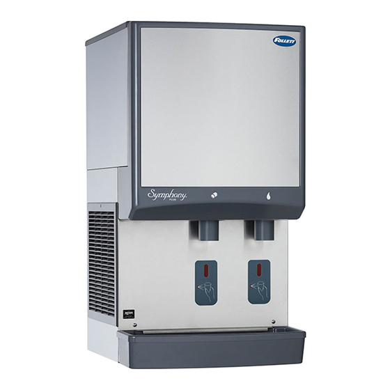
25/50CI400A/W-SI Countertop
Ice-only Dispenser with
SensorSAFE™ Dispensing
25/50CI400A/W-S Countertop Dispenser
with SensorSAFE™ Dispensing
25CI400A/W, 25HI400A, 50CI400A/W, 50HI400A
25/50CI400A/W-LI Countertop Ice-only
Dispenser with Lever Dispensing
25/50CI400A/W-L Countertop Dispenser
with Lever Dispensing
Following installation, please forward this manual
to the appropriate operations person.
801 Church Lane • Easton, PA 18040, USA
Toll free (877) 612-5086 • +1 (610) 252-7301
www.follettice.com
Ice and Water Dispensers
Installation, Operation and Service Manual
25/50HI400A-S Wall Mount Dispenser
25/50HI400A-SI Wall Mount
Ice-only Dispenser with
SensorSAFE Dispensing
with SensorSAFE Dispensing
00187153R07
Advertisement
Chapters
Table of Contents
Troubleshooting

Subscribe to Our Youtube Channel
Related Manuals for Follett Symphony 25CI400A


Summary of Contents for Follett Symphony 25CI400A
- Page 1 Ice and Water Dispensers 25CI400A/W, 25HI400A, 50CI400A/W, 50HI400A Installation, Operation and Service Manual Order parts online www.follettice.com 25/50CI400A/W-SI Countertop 25/50CI400A/W-LI Countertop Ice-only 25/50HI400A-SI Wall Mount Ice-only Dispenser with Dispenser with Lever Dispensing Ice-only Dispenser with SensorSAFE™ Dispensing SensorSAFE Dispensing 25/50CI400A/W-S Countertop Dispenser 25/50CI400A/W-L Countertop Dispenser 25/50HI400A-S Wall Mount Dispenser with SensorSAFE™...
-
Page 2: Table Of Contents
Contents Welcome to Follett ........3 Wiring diagram - SensorSAFE model ....22 Before you begin . -
Page 3: Welcome To Follett
After uncrating and removing all packing material, inspect the equipment for concealed shipping damage. If damage is found, notify the shipper immediately and contact Follett Corporation so that we can help in the fi ling of a claim, if necessary. -
Page 4: Specifi Cations
Specifi cations Countertop Front View Right Side View Rear View 21" (534mm) 24" (610mm) 3/8" FPT condenser inlet (water- cooled only) 3/8" FPT 25CI400A/W condenser 36" outlet (water- (915mm) cooled only) 3/4" FPT drain 50CI400A/W 40" 3/8" water (1016mm) inlet 10.5"... -
Page 5: Electrical
Electrical 115V, 60Hz, 1 phase, 14.0 amps. Connect to dedicated 20 amp circuit, fuse or breaker. Note: It is preferred that circuit be protected by a GFCI. Furnished with 7 ft (2m) power cord with a 90° NEMA hospital grade 5-20 plug. Ambient Maximum Minimum... -
Page 6: Installation
Installation Fig. 2 Utility connections as viewed from top for countertop back access Before you begin condenser outlet potable water Level dispenser in both directions to ensure proper drain 3/8" FNPT 3/8" FNPT 3/4" FNPT operation. condenser inlet 3/8" 3/8" FNPT Provide clearances noted in clearances table on page 5. - Page 7 Fig. 4 12. Raise the dispenser upright and position in desired location. 13. Mark dispenser outline on counter and remove dispenser. Fig. 6 Countertop cutout viewed from top 3.13" 16.00" (80mm) (407mm) 1.56" (40mm) 12.50" Cutout (318mm) connections 14" through (356mm) bottom Ø.375"...
-
Page 8: Installing Wall Mount Dispensers
Installing wall mount dispensers Fig. 9 WARNING • Wall mount dispensers are intended to be mounted above a sink, eliminating the need for a drain pan. • Before beginning installation verify that the sink size and location meet the requirements shown in Fig. 7. •... - Page 9 Fig. 10 Dispenser bottom view 10.3 10.1 10.2 7. Connect supplied 3/8" water line between water supply and water inlet fitting (Fig. 10.1). 8. Using supplied 3/4" drain tubing and barbed fittings, connect 3/4" barbed drain elbow fi tting on dispenser to 3/4"...
-
Page 10: Icemaker Cleaning & Sanitizing
Solution temperature must be at least 120 F (49 C). CAUTION WARNING: Most ice machine cleaners contain • Use only Follett approved cleaners (see procedure below) citric or phosphoric acid that can cause skin • It is a violation of Federal law to use these solutions in a manner inconsistent with their labeling irritation. -
Page 11: Start-Up Following Cleaning
20. Turn power to icemaker OFF. 21. Disconnect transport tube from evaporator outlet port. Rinse compression nozzle in clean water and reinstall on evaporator outlet. Reconnect transport tube to compression nozzle. 22. Drain any remaining sanitizing solution from evaporator. 23. Fill reservoir almost to overfl owing with clean, 120 F (49 C) water, and drain. -
Page 12: Dispenser Cleaning & Sanitizing
CAUTION 1. Remove ice from dispenser. Disconnect power. • Use only Follett approved cleaners (see procedure below). • It is a violation of Federal law to use these solutions in a 2. Working inside storage area, remove center... -
Page 13: Service
The icemaking process The Follett icemaker uses a stainless steel jacketed evaporator and operates on a continuous freezing cycle. Water is supplied to the evaporator from the water reservoir where the water level is controlled by a fl oat valve. -
Page 14: Disassembly And Replacement Instructions
(Fig. 15.1) and spread with pliers CAUTION before making connection (Fig. 15.2). • Tubing must be supplied by Follett Corporation 8. Slip supplied hose clamp onto tube and push tube onto compression nozzle on exit port of evaporator. -
Page 15: Icemaker Removal
Icemaker removal Fig. 18 – All models WARNING To reduce risk of shock disconnect power before servicing. Fig. 16– All models 18.1 18.2 3. Lower drain pan protector (Fig. 18.1). Remove and discard shipping screw (Fig. 18.2). Fig. 19 – All models 19.4 19.3 1. - Page 16 Fig. 20 – Water-cooled only Fig. 22 – All models 22.4 22.1 20.1 22.3 22.2 9. Partially slide icemaker from dispenser (Fig. 22.1). 10. Loosen clamp and disconnect ice transport tube 7. Shut off inlet and outlet valves to water-cooled from evaporator (Fig.
- Page 17 Fig. 24 – Water-cooled only 24.1 24.2 13. Use hooks on icemaker electrical box to hang box on bracket (Fig. 24.1). 14. Remove icemaker from dispenser (Fig. 24.2). Fig. 25 – All models WARNING • Electrical box must be in “UP” position before supplying power •...
-
Page 18: Evaporator Disassembly
Evaporator disassembly Evaporator reassembly Note: The upper bearing, lower bearing and auger 1. Clean gearmotor boss, output shaft and shaft well. assemblies must be replaced as assemblies. The bottom 2. Install drain pan and evaporator mounting base. and top bearing assemblies cannot be fi eld assembled to 3. -
Page 19: Gearmotor Replacement
Gearmotor replacement 1. Disassemble evaporator as described above. 2. Disconnect the wire connectors. 3. Remove four screws holding gear motor mounting plate to base of icemaker and lift gearbox and motor clear of icemaker. 4. Remove machine screws holding mounting plate to motor. -
Page 20: Electrical Systems
Electrical systems Electrical component locations Top View WARNING To reduce risk of shock disconnect power before servicing. WARNING • Electrical box must be in “UP” position before supplying power • Start relay is gravity sensitive, and MUST be in “UP” position •... -
Page 21: Wiring Diagram - Lever Dispense Model
Wiring diagram - lever dispense model START GEAR MOTOR BISON GEAR 2 BLACK START MOTOR YELLOW T.O.L. START GEAR MOTOR START LINIX GEAR T.O.L. MOTOR 25CI400A/W • 25HI400A • 50CI400A/W • 50HI400A... -
Page 22: Wiring Diagram - Sensorsafe Model
Wiring diagram - SensorSAFE model START GEAR MOTOR BISON GEAR 2 BLACK START MOTOR YELLOW T.O.L. START GEAR MOTOR START LINIX GEAR T.O.L. MOTOR 25CI400A/W • 25HI400A • 50CI400A/W • 50HI400A... -
Page 23: Icemaker Operational And Diagnostic Sequences
Icemaker operational and diagnostic sequences The wiring diagrams that follow illustrate the circuitry of Follett icemakers. Both normal operation (stages 1 - 6) and non-normal diagnostic sequences showing torque-out (stages 7 - 10) for use in troubleshooting are shown. Circuitry notes The icemaker receives power from two sources –... -
Page 24: Normal Operation - Stage 1
Normal operation – Stage 1 Power is supplied to L1 of the control board. The ice level control in the dispenser is closed and calling for ice, supplying signal voltage to the control board. The control board will now go through the start-up sequence. Less than 30 seconds will elapse as the water sensor located in the fl oat reservoir checks for water in the reservoir. -
Page 25: Normal Operation - Stage 3
Normal operation – Stage 3 After the initial high current draw drops off, the gearmotor start relay contacts open, dropping out the start winding (or start capacitor). As the compressor comes up to normal running speed, the compressor start relay contacts also open, dropping out the start winding of the compressor. -
Page 26: Normal Operation - Stage 5
Normal operation – Stage 5 The drive motor now shuts down and the DR LED is off. The B-T LED remains on for 20 minutes. The icemaker will not start while the B-T LED is on. To restart the icemaker for troubleshooting purposes, depress the reset button to clear the control board. -
Page 27: Diagnostic Sequence - Stage 7
Diagnostic sequence – Stage 7 The 20 minute error LED (20M) is on, indicating that the control board has sensed an over-torque condition (above 3 AMPS on the gearmotor). The 20M LED remains on for 20 minutes after an over-torque condition has occurred. The icemaker remains off as long as the 20M LED is on. -
Page 28: Diagnostic Sequence - Stage 9
Diagnostic sequence – Stage 9 The second error (2ND) LED comes on if an over-torque condition occurs while the 60M LED is still lighted. The 2ND LED indicates that two consecutive over-torque situations have occurred. The icemaker will be shut down at this time and will not restart unless the manual reset button is depressed. -
Page 29: Refrigeration Cycle
Refrigeration cycle high pressure high side service port switch condenser low side filter dryer service port compressor evaporator high high pressure pressure pressure pressure thermostatic vapor vapor liquid liquid expansion valve 25CI400A/W • 25HI400A • 50CI400A/W • 50HI400A... -
Page 30: Refrigeration Data
Total test time in minutes 700-88. 9. Calculated amount per 24 hours should be checked 3. Follett Corporation does not approve of recovered against rated capacity for same ambient and water refrigerants. Improper refrigeration servicing temperatures in Ice Production Table (above). -
Page 31: Dispenser Troubleshooting
Dispenser troubleshooting Before calling for service WARNING 1. Check for ice in the ice storage area. • Disconnect power to unit before putting hands or arms in storage area or attempting 2. Check that congealed ice is not causing a jam. any repair or service to equipment 3. -
Page 32: Icemaker Troubleshooting
2. Remove obstruction. Poor quality ice. 3. Mineral coated evaporator. 3. Clean evaporator. 4. Improper exhaust air provisions. 4. Provide proper exhaust air provisions per Follett installation manual. 5. Faulty expansion valve. 5. Replace expansion valve. 6. Low refrigerant charge. - Page 33 3. Clogged or dirty air fi lter or condenser coil. 3. Clean or replace fi lter, clean condenser coil. 4. Improper ventilation. 4. Provide inlet and exhaust air provisions per Follett icemaker installation manual. 5. Defective compressor. 5. Replace compressor.
-
Page 34: Dispenser Replacement Parts
Dispenser replacement parts Dispenser exterior Part # Description Reference 501608 Baffle, ice 502821 Wheel, dispense (includes 501612) 502712 Bracket, ice tube 501612 Rod, threaded (includes knurled nut) 0996030 Ice transport tube, 25 series 00196048 Ice transport tube, 50 series 00192963 Louver, exhaust 502682 Drain pan... -
Page 35: Lever Models
Dispense chute and splash panel areas – lever models Part # Description Reference 502057 Fastener, dispense chute bracket 00187682 Tube, water station 00185116 Bracket, lever 502409 Switch, dispense, ice, lever actuated (includes 502418) 502409 Switch, dispense, water, lever actuated (includes 502418) 00192864 Bracket, chute (includes fasteners 502057) 00182808... -
Page 36: Dispenser Electrical Box - Lever Models
Dispenser electrical box – lever models Part # Description Reference 500514 Thermostat 502209 Switch, dispenser power 502209 Switch, icemaker bin signal 00195818 Cord and socket (female), icemaker power 00195826 Cord and socket (female), bin signal 502336 Socket (female), icemaker power 502334 Socket (female), bin signal 502776... -
Page 37: Dispense Chute And Splash Panel Areas - Sensorsafe Models
Dispense chute and splash panel areas – SensorSAFE models Part # Description Reference 502057 Fastener, dispense chute bracket 00187682 Tube, water station 00195982 Sensor, ice dispense 00195982 Sensor, water dispense 00196006 Lens, sensors 00192864 Bracket, chute (includes fasteners 502057) 502359 Clean switch, SensorSAFE (includes 501841) 00192948 Chute and funnel, ice... -
Page 38: Dispenser Electrical Box - Sensorsafe Models
Dispenser electrical box – SensorSAFE models Part # Description Reference 500514 Thermostat 502209 Switch, dispenser power 502209 Switch, icemaker bin signal 502242 Board, SensorSAFE 501959 Standoff, board (4 required) 00195818 Cord and socket (female), icemaker power 00195826 Cord and socket (female), bin signal 502336 Socket (female), icemaker power 502334... -
Page 39: Wheel Motor And Drive System
Wheel motor and drive system Part # Description Reference 501861 Wheel motor, 120V, 60Hz 501026 Washer, thrust 501607 Fan blade, wheel motor 00182246 Chain, pitch 64, link Not shown 502692 Sprocket, drive shaft, 35T (includes 500367) 501019 Sprocket, wheel motor, 10T 501024 Bearing, drive shaft 500799... -
Page 40: Water And Drain
Water and drain Countertop connections (CI) (top view) Wall mount connections (HI) (bottom view) Part # Description Reference 502921 Valve, water shut off 502922 Clip, shut off valve 00134502 Elbow, 1/4" x 3/8" 502923 Tee, 1/4" 502920 Strainer 502925 Elbow, 3/8" 00184549 Drain tube, hopper 00195958... -
Page 41: Icemaker Replacement Parts
Icemaker replacement parts Evaporator Part # Description Reference 502735 Coupling, vee band, includes nut 502736 Bearing assembly, top 502110 Loop, ice compression, beveled 502737 Auger 502725 Evaporator (includes insulation jacket, 502740) 500496 O ring, bearing housing 502738 Bearing assembly, bottom (includes O rings and condensate shield) 501063 O ring, mounting base... -
Page 42: Air-Cooled Icemakers
Air-cooled icemakers 25CI400A/W • 25HI400A • 50CI400A/W • 50HI400A... - Page 43 Part # Description Reference 502724 Drier 00195917 Condenser coil, air-cooled 502116 Water sensor Not shown 00163824 Reservoir mounting bracket 500504 Float valve & reservoir 00187187 Reservoir overfl ow tube with Agion 00141440 Drain kit with Agion, evaporator Not shown Evaporator (see page 41 for complete breakdown) 502079 Tubing, polypropylene, reservoir supply (sold by foot) Not shown...
-
Page 44: Water-Cooled Icemakers
Water-cooled icemakers 25CI400A/W • 25HI400A • 50CI400A/W • 50HI400A... -
Page 45: Not Shown
Part # Description Reference 502724 Drier 500537 Valve, water regulating (includes 501810) 501810 Iso-washer (for water regulating valve) Not shown 502116 Water sensor Not shown 500504 Float valve & reservoir 00195941 Reservoir mounting bracket 502079 Tubing, polypropylene, reservoir supply (sold by foot) Not shown 502078 Fitting, plastic, fl oat valve (includes sleeve &... -
Page 46: Icemaker Electrical Components
Icemaker electrical components Part # Description Reference 502780 Capacitor, start, compressor, 115V, 60Hz 501588 Relay start, compressor, 115V, 60Hz 502331 Board, control circuit, 115V, 60Hz 502116 Water sensor Not shown 502392 Switch, on/off, compressor 501959 Board, stand off control (4 required) 00195834 Cord and plug (male), icemaker power 00195842... - Page 47 25CI400A/W • 25HI400A • 50CI400A/W • 50HI400A...
- Page 48 Chewblet is a registered trademark of Follett Corporation, registered in the US. Follett reserves the right to change specifi cations at any time without obligation. Certifi cations may vary depending on country of origin. 801 Church Lane • Easton, PA 18040, USA 00187153R07 Toll free (877) 612-5086 •...
Need help?
Do you have a question about the Symphony 25CI400A and is the answer not in the manual?
Questions and answers