Follett 25 Installation, Operation & Service Manual
25 and 50 series ice and water dispensers
Hide thumbs
Also See for 25:
- Installation, operation and service manual (36 pages) ,
- Installation, operation and service manual (36 pages)
Table of Contents
Advertisement
Order parts online
www.follettice.com
25CR400A/W 50CR400A/W
Installation, Operation and Service Manual
25CT400A/W
50CT400A/W
™
(shown with SensorSAFE
accessory)
Following installation, please forward this manual
to the appropriate operations person.
801 Church Lane • Easton, PA 18040, USA
Toll free (800) 523-9361 • (610) 252-7301
Fax (610) 250-0696 • www.follettice.com
Ice and Water Dispensers
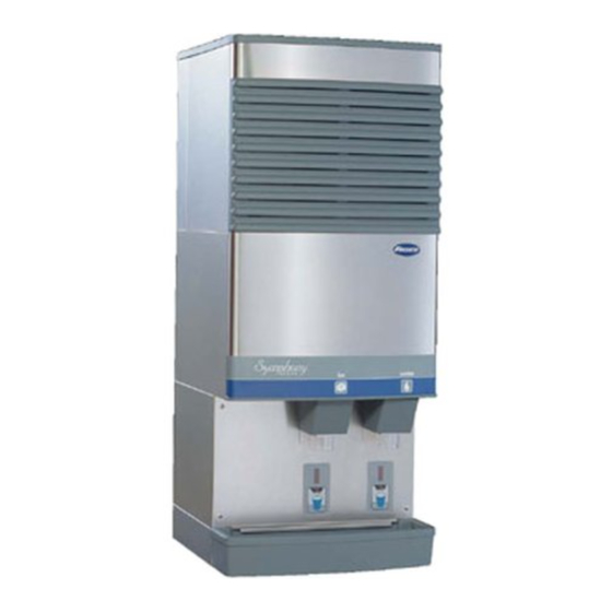
25HT400A/W
(shown with SensorSAFE accessory)
25HR400A/W 50HR400A/W
25 and 50 Series
50HT400A/W
25FB400A/W
50FB400A/W
(shown with SensorSAFE accessory)
208596R07
Advertisement
Table of Contents
Troubleshooting

Related Manuals for Follett 25


Summary of Contents for Follett 25
- Page 1 25HR400A/W 50HR400A/W to the appropriate operations person. 801 Church Lane • Easton, PA 18040, USA Toll free (800) 523-9361 • (610) 252-7301 Fax (610) 250-0696 • www.follettice.com 25 and 50 Series 25HT400A/W 50HT400A/W (shown with SensorSAFE accessory) 25FB400A/W 50FB400A/W...
-
Page 2: Table Of Contents
A return authorization number has been issued by customer service within 30 days after shipment. Follett receives the equipment at the factory in Easton, PA within 30 days after issuance of the return authorization number. The equipment must be returned in Follett packaging. If the packaging has been damaged or discarded, Follett will forward, at the customer’s expense, new packaging. -
Page 3: Welcome To Follett
Before you begin After uncrating and removing all packing material, inspect the equipment for concealed shipping damage. If damage is found, notify your shipper immediately and contact Follett Corporation for help in filing a claim, if necessary. Check your paperwork to determine which model you have. Follett model numbers are designed to provide information about the type and capacity of Follett equipment. -
Page 4: Specifications
Connect to 20 amp circuit fuse or breaker. Note: It is preferred that circuit be protected by a GFCI. Ambient Air temp Water temp Water pressure Plumbing 25/50 CR with Satellite-fill icemaker Dispenser drain 3/4" FPT Icemaker drain 3/4" MPT Dispenser water inlet 3/8"... -
Page 5: Field Wiring
Field wiring for countertop and wall mount dispensers with Satellite-fill icemakers All field wiring must be installed in accordance with NEC and local electrical codes. Field wiring diagram is intended only to aid electrician or technician in understanding how equipment works. Model 25FB400A/W, 50FB400A/W 25CT400A/W, 50CT400A/W... -
Page 6: Field Wiring Diagrams
Field Wiring diagrams (For installations requiring hard-wiring equipment) Freestanding dispensers, countertop and wall mount dispensers with integral icemakers FIELD WIRING DIAGRAM IS INTENDED TO AID ELECTRICIAN OR TECHNICIAN IN UNDERSTANDING HOW EQUIPMENT WORKS. ALL FIELD WIRING MUST BE INSTALLED IN ACCORDANCE WITH NEC AND LOCAL ELECTRICAL CODES. -
Page 7: Installation
Installation procedure Before you begin • All dispensers must be installed level in both directions to ensure proper operation • Required ventilation and recommended service clearances: • Countertop and wall mount models with Satellite-fill icemaker (25CR400A/W, 25HR400A/W, 50CR400A/W, 50HR400A/W) — none. 12" (305mm) at top recommended for service •... - Page 8 19. Turn icemaker bin signal switch on and replace front covers, securing with screws. .8" (20mm) 10.5" (267mm) 6.75" (171mm) 15.125" (384mm) 10.25" (259mm) 3.125" (79mm) access panel (B) 3/4" FPT drain power cord (D) 3/8" FPT condenser inlet location (water-cooled only) (E) 3/8"...
-
Page 9: Installing Countertop Dispensers
2. Drill four 3/8" (5mm) holes in counter (Fig. 2) to anchor dispenser to counter. Follett countertop dispensers can have any or all utilities run directly through counter or out rear of dispenser. For dispensers with any utilities exiting through counter, make counter cut-out (Fig. - Page 10 5. If power is to be supplied through counter cut-out, complete steps 6-9. If power is to be supplied through rear of dispenser, proceed to step 10. 6. Temporarily remove rear access panel (Figs. 4 and 5) from rear of dispenser. 7.
-
Page 11: Installing Wall Mount Dispensers
Installing wall mount dispensers 1. Install supplied wall bracket with six 3/8" diameter fasteners as shown in Fig. 7. Note: Three holes are available at each fastening site to allow capture of studs/support within wall. Steps 2 - 3 are required for models with integral icemaker only (25HT400A/W and 50HT400A/W). 2. - Page 12 11. Proceed with either remote or top-mounted icemaker connection instructions, as appropriate. Fig. 7 – Mounting dimensions for wall mount units without drain pan with Satellite-fill icemaker 16" (406mm) wall stud 25HT400A/W 25HR400A/W 9.5" (241mm) 25.5" 50HT400A/W (648mm) 11.5" (292mm) 50HR400A/W 29.5" 25HT400A/W (749mm) 9.5" (241mm) 50HT400A/W 11.5"...
-
Page 13: Installing Satellite-Fill ™ Icemakers
Installing Satellite-fill icemakers Models 25CR400A/W, 50CR400A/W, 25HR400A/W, 50HR400A/W See Icemaker Installation Manual (form #208600) for critical installation instructions for Satellite- fill icemakers. Failure to comply with these instructions will result in poor performance and void warranty. 1. Install Satellite-fill icemaker following instructions in icemaker manual. 2. -
Page 14: Installing Top Mount Icemakers
Installing top mount icemakers Models 25CT400A/W, 50CT400A/W, 25HT400A/W, 50HT400A/W Dispensers with top mount icemakers cannot be mounted on legs. They must be bolted to counter. Use gloves when lifting icemaker to protect hands from sheet metal edges. 1. On dispensers equipped with top-mounted, water-cooled icemakers, feed condenser supply and drain lines from back through utility knock-out (Fig. - Page 15 Fig. 11 – Ice transport tube and ice level control stat mounting units with top-mounted icemakers .75" ice level control stat (19mm) Hand bend cap tube end to approx. 45 as shown...
-
Page 16: User Information
How the dispenser works Follett’s 25 and 50 automatic load ice and water dispensers receive ice from Follett’s 400 lb (181kg)/day icemaker located in the dispenser base, in the cabinet top or in a remote location up to 20 ft (6m) away. Ice produced is stored in the bin section of the dispenser. - Page 17 If dispenser is a SensorSAFE unit: 3. Deactivate dispenser by depressing and releasing clean switch located on left side of unit under top front cover. 4. Clean lens using soft cloth and mild, non-abrasive cleaner. 5. Reactivate dispenser by depressing and releasing clean switch a second time (dispenser automatically reactivates after two minutes).
-
Page 18: Service Information
Service information Wiring diagrams How unit works — lever models The dispense wheel motor is energized through the power and ice dispense switches. The water solenoid valve is energized through the power and water dispense switches. The icemaker receives the bin signal through the power switch, the normally closed bin thermostat and the icemaker switch. -
Page 19: Wiring Diagram - Sensorsafe Models
How unit works — SensorSAFE models SensorSAFE models provide “touchless” ice and water dispensing. When a container is placed within the actuation zone below the ice or water chute on SensorSAFE dispenser models, an infrared signal reflects off the container and is detected by the sensor. -
Page 20: Dispenser Troubleshooting
Dispenser troubleshooting Disconnect power to dispenser and icemaker before putting hands or arms in storage area, or attempting any repair or service to equipment. Before calling for service: • Check that there is ice in dispenser bin area • Check that congealed cubes are not causing a jam Symptom 1. -
Page 21: Troubleshooting Sensorsafe Board And Sensors
Troubleshooting SensorSAFE board and sensors Board guide LEDs, when illuminated, indicate the following: PWR (board power) CLN (cleaning, no dispensing cycle) ICE (ice dispensing activated) WTR (water dispensing activated) Problem: Does not dispense ice or water Action Check LEDs on control board Place cup under drop zone... -
Page 22: Lens/Sensor Troubleshooting
Lens/sensor troubleshooting 1. Turn dispenser power switch off. 2. Remove splash panel. 3. Disconnect wires from output terminal(s) (WTR, WM) on board. 4. Gently remove appropriate sensor/mounting block assembly from panel by moving block sideways until edge of block clears retaining tab of panel. 5. -
Page 23: Disassembly And Replacement Instructions
4. Disconnect wiring to panel and set panel aside. 5. Disconnect wires on motor. 6. Remove four bolts (7/16" socket) holding motor assembly to bottom of dispenser. Ice transport tube replacement Models 25CT400A/W, 25HT400A/W, 50CT400A/W, 50HT400A/W Only use tubing supplied by Follett Corporation. baffle dispenser front 1/16" (1.6mm) -
Page 24: Ice Transport Tube Replacement
All units 9. Slip supplied hose clamp onto tube and push tube onto exit port of evaporator. Only use tubing supplied by Follett Corporation. Do not twist hose when securing to evaporator. 10. Fasten tube on port with hose clamp, being sure that clamp is positioned on evaporator side of nozzle flange. -
Page 25: Thermostat Locations
Thermostat locations Thermostat locations – 25CT400A/W, 25HT400A/W, 50CT400A/W, 50HT400A/W ice deflector bracket assembly rubber grommet ice level control stat Thermostat locations – 25CR400A/W, 50CR400A/W, 25HR400A/W, 25FB400A/W, 50HR400A/W, 50FB400A/W well nut rubber grommet ice level control stat hopper assembly control box assembly .75"... -
Page 26: Parts
502683 Grille, drain pan 502688 Lid, icemaker, 25/50, countertop (CT) and wall mount (HT) units 502684 Lid, 25/50, countertop (CR), wall mount units with Satellite-fill icemakers (HR) & freestanding (FB) units 502699 Rear panel, base stand, perforated 502088 Leg kit, 6" (153mm), adjustable, for freestanding units – set of 4... -
Page 27: Dispense Chute And Splash Panel Areas - Lever Models
Dispense chute and splash panel areas — lever models Part # Description 502057 Fastener, dispense chute bracket 502356 Tube, water station 502681 Cover, dispense chute 502359 Switch, dispense, ice, lever actuated (includes 501841) 502359 Switch, dispense, water, lever actuated (includes 501841) 502247 Bracket, chute (includes fasteners 502057) 502358... -
Page 28: Dispense Chute And Splash Panel Areas - Sensorsafe Models
Dispense chute and splash panel areas — SensorSAFE models Part # Description 502057 Fastener, dispense chute bracket 502681 Cover, dispense chute (includes labels) 502689 Chute and funnel, ice 502249 Chute, water 00129908 Chute and funnel, ice, wall mount, no drain pan 00129155 Chute, water, wall hung, no drain pan 502247... -
Page 29: Electrical Box - Sensorsafe Models
Electrical box (front view) – SensorSAFE models Part # Description 500514 Thermostat, bin level 502209 Switch, dispenser power 502209 Switch, icemaker bin signal 502242 Control board, SensorSAFE 502359 Clean switch, SensorSAFE 501841 Boot, clean switch Wheel motor and drive system Part # Description 501861... -
Page 30: Hopper Components
Hopper components Top view – all top mounted units Dispense wheel – bottom view all units Part # Description 501608 Baffle, ice 501614 Wheel, dispense (includes drive bar, rotating agitator, threaded bar & rod) 502821 Wheel, dispense (wheel only) 501609 Agitator, rotating 502712 Bracket, ice tube... -
Page 31: Ice Transport Tubing
Ice transport tube insulation (Satellite-fill units only) - sold by the foot 502328 Ice transport tube assembly (50 freestanding (FB) units) 502329 Ice transport tube assembly (25 freestanding (FB) units) 502697 Ice transport tube assembly (top mount units) Chilled water components... -
Page 32: Countertop Dispenser Plumbing Connections
Countertop dispenser plumbing connections Mounting plate fittings Part # Description 00136663 Strainer 502222 Valve, water shut-off 502685 Drain tube assembly 502100 Fitting, water inlet with mounting plate 502682 Drain pan 502718 Elbow 502433 Tee, water inlet Bulkhead fittings Part # Description 00136663 Strainer...
Need help?
Do you have a question about the 25 and is the answer not in the manual?
Questions and answers