Table of Contents
Advertisement
Quick Links
Advertisement
Table of Contents

Related Manuals for Rhin-O-Tuff OD4012


Summary of Contents for Rhin-O-Tuff OD4012
- Page 1 Instruction Book for the OD4012, OD4000 and OD4800...
- Page 2 No matter what type of binding you need to carry out, these punches can handle the job. The maximum single punching length for the OD4012, OD4000 and OD4800 is a 11” (297mm) format. The OD4012 and the OD4000 are electrically operated punches and the OD4800 is manually operated.
- Page 3 OD4012 Contents S/N:____________ ___Punch (1) ___Instruction Book (1) ___Oil (1) ___Brush (1) ___Foot Pedal (1) ___Power Cord (1) ___Reversing Tool (1) Inspected by: __________________ OD4000 Contents S/N:____________ ___Punch (1) ___Instruction Book (1) ___Knob Kit (1) ___Oil (1) a) ¼-20 x 1 ½” Knob (2)
-
Page 5: Table Of Contents
Table of Contents Topic: Page Number: Safety Alert Symbols Safe operating guidelines Proper machine placement Attach OD4800 Handle Providing electric power Die installation / Maintenance Setting the paper stop/guide Punching paper Removing paper waste Paper jam 11-12 Troubleshooting... -
Page 6: Safety Alert Symbols
Always keep this instruction manual with the machine for reference to safe operating guidelines and correct operation of the machine. The OD4012 and OD4000 need to be plugged into a wall outlet that provides a 15-amp, 120 volt service (16-amp, 220 volt for European installations) and is protected by a fuse or circuit breaker at the main electrical panel. -
Page 7: Proper Machine Placement
Turn power switch off before maintaining or WARNING changing die assembly. Crush hazard. Keep hands away from moving parts. Lockout and disconnect power before servicing. Use of appropriate hand protection should be CAUTION utilized to avoid injury from handling of materials. Cutting Hazard Injury to fingers and hands. -
Page 8: Attach Od4800 Handle
Attach Handle to OD4800: The OD4800 manual punch is shipped with the handle removed from the punch. You will need two 3/8” wrenches (not supplied) to tighten the handle bolt. Locate the handle and remove the nut, washer and bolt from the handle. -
Page 9: Providing Electric Power
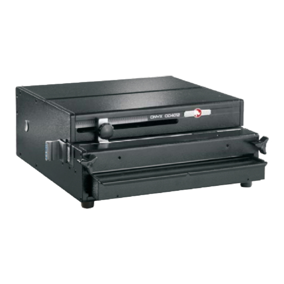
Install die until right side of die is flush to exterior of right side of machine. Thread both retained die lock knobs into the die and tighten evenly until the die can not move. Punch Pin Retainer Die Lock Knob Diagram 2. (Image of OD4012) - Page 10 Diagram 3. (Image of OD4000) Comb Die Backspace (Margin) Adjustment The comb die assemblies for the OD4012, OD4000, and OD4800 have a four position adjustable backspace. The positions are changed by pulling the adjustor bar to the left for deeper settings (commonly...
- Page 11 Removing Punch Pins Turn machine power off and remove die assembly from the machine. On the opposite side of the die assembly from the die handle, push Pull the pin capture away from the pin retainer to expose the punch pins.
-
Page 12: Setting The Paper Stop/Guide
Repeat this procedure until the punch pattern is centered on the paper. The OD4012, OD4000 and OD4800 punch machines allow for viewing of Paper Stop the common size paper position markings on the die assemblies. Aligning the paper stop with these marks will result in the punch pattern being centered on the paper and need only small adjustments if at all. -
Page 13: Paper Jam
Paper Jam: The OD4012 and OD4000 punches use a circuit board for controlling the punch cycle, this circuit board also has the ability to automatically reverse the pusher bar and punch pins to their starting position if the machine takes too much time to complete a punch cycle. This condition could happen if too much material has been attempted to be punched at one time. - Page 14 Turn the machine OD4000 Manual Reverse WARNING power switch off and unplug the power Crush hazard. Keep hands away cord from the wall. Locate the silver plug from moving parts. Lockout and disconnect on the rear of the left side panel of the power before servicing.
-
Page 15: Troubleshooting
3) Move handle to unlock position NOTICE The OD4012 and OD4000 have been tested with a duty cycle of 25 cycles per minute with a 1 minute rest period after 2 minutes of run time. Operating outside of these limits could result in machine damage. - Page 16 IMPORTANT Be sure to fill out and return your Product Warranty Registration Card or Register online www.Rhin-O-Tuff.com/warranty_registration.asp Part Number 001172 Rev. 3 Aug 2010...
Need help?
Do you have a question about the OD4012 and is the answer not in the manual?
Questions and answers