Table of Contents
Advertisement
600B718/08
INSTALLER GUIDE
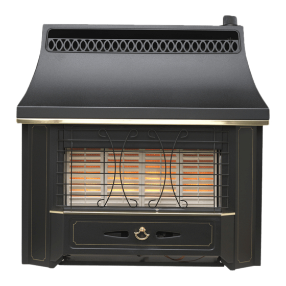
B L A C K B E A U T Y
R a d i a n t
Gas Fire
MODEL 340
(GC No. 32-032-33)
THIS APPLIANCE IS FOR USE WITH NATURAL GAS (G20)
THIS APPLIANCE IS FOR USE IN THE UNITED KINGDOM (GB) AND
THE REPUBLIC OF IRELAND (IE) ONLY.
We trust that this Installer Guide gives sufficient details to enable the appliance to be
installed and maintained satisfactorily. However, if further information is required, our
Valor Technical Helpline will be pleased to help.
Please telephone 08706 061 065 (National call rates apply in the United Kingdom).
INSTALLER: Please leave this guide with the owner
© Valor Heating
Advertisement
Table of Contents

Subscribe to Our Youtube Channel
Related Manuals for Valor Black Beauty Radiant


Summary of Contents for Valor Black Beauty Radiant
- Page 1 We trust that this Installer Guide gives sufficient details to enable the appliance to be installed and maintained satisfactorily. However, if further information is required, our Valor Technical Helpline will be pleased to help. Please telephone 08706 061 065 (National call rates apply in the United Kingdom).
-
Page 2: Table Of Contents
11.5 To Remove The Complete Burner Module, Pipes and Pilot ........ 20 11.6 To Grease the Gas Tap ..................21 REPLACEMENT PARTS – SHORT LIST ..............21 Valor Heating, Erdington, Birmingham B24 9QP www.valor.co.uk Because our policy is one of constant development and improvement, details may vary slightly from those given in this publication. -
Page 3: Safety
INSTALLER’S GUIDE 1 S A F E T Y Installer • Before continuing any further with the installation of this appliance please read the following guide to manual handling • The lifting weight of this appliance is 15.74 kg. One person should be sufficient to lift the fire. -
Page 4: Appliance Data
INSTALLER’S GUIDE 3 A P P L I A N C E D A T A This appliance does not contain any component manufactured from asbestos or asbestos related products. The appliance data label is on the inner face of the back panel at the lower left-hand side. It is visible when the outer case is removed. -
Page 5: General Installation Requirements
INSTALLER’S GUIDE 4 G E N E R A L I N S T A L L A T I O N R E Q U I R E M E N T S The installation must be in accordance with these instructions. For the user’s protection, in the United Kingdom it is the law that all gas appliances are installed by competent persons in accordance with the current edition of the Gas Safety (Installation and Use) Regulations. - Page 6 INSTALLER’S GUIDE Figure 1. Dimensions & clearances Note that soft wall coverings (e.g. embossed vinyl, etc.) are easily affected by heat. They may scorch or become discoloured when close to a heating appliance. Please bear this in mind when installing. The minimum side clearances to combustible surfaces and recommended side access clearances are given in figure 1.
- Page 7 In the United Kingdom, as supplied, this appliance can be installed in the following situations: - Note: A spigot extension is available (Valor part number 0595191). When fitted this shall extend through the closure plate for at least 15mm and have a minimum clearance of 50mm from the end to any surface.
- Page 8 INSTALLER’S GUIDE Though the total height of the closure plate will accommodate a maximum opening height of 650mm, heights above 610mm will leave the closure plate and sealing tape visible above the appliance. The appliance must be mounted on a non-combustible hearth (N.B. conglomerate marble hearths are considered as non-combustible).
- Page 9 INSTALLER’S GUIDE Though the total height of the closure plate will accommodate a maximum opening height of 650mm, heights above 610mm will leave the closure plate and sealing tape visible above the appliance. Any opening visible below the appliance may be closed in. 4.9.4 Metal Flue Box The appliance can be installed to a metal flue box conforming to BS715 Section 6 (For gas fires to BS5258: Part 5) having a minimum internal depth of 165mm.
- Page 10 INSTALLER’S GUIDE products of combustion can be safely dispersed into the outside atmosphere. Where the appliance is connected to an unlined brick chimney it is generally unnecessary for the chimney pot to be replaced or for a terminal to be fitted unless the flue has a diameter smaller than 170mm.
-
Page 11: Pre-Installation Preparation
INSTALLER’S GUIDE 5 P R E - I N S T A L L A T I O N P R E P A R A T I O N 5.1 Unpacking This appliance is supplied completely assembled except for: - 3 radiants which are in a cardboard pack inside the firebox. -
Page 12: Fit The Closure Plate
INSTALLER’S GUIDE knob to the spindle. Depress the knob and while keeping it depressed, turn to the 1/IGN position. A spark should track from the electrode pin to the thermocouple tip. If there is no spark or incorrect tracking, check the spark gap between the electrode wire and thermocouple tip. - Page 13 INSTALLER’S GUIDE 5.4.1 Hearth mounting See figure 7. The closure plate must be fitted and sealed to the hearth and fireplace opening using a suitable heat resistant material. If necessary cut the closure plate but make sure that it overlaps the fireplace opening sufficiently to allow satisfactory sealing.
-
Page 14: Appliance Installation
INSTALLER’S GUIDE 6 A P P L I A N C E I N S T A L L A T I O N 6.1 Installing To A Hearth 6.1.1 Place the fire centrally on the hearth making sure that the spigot lines up with the spigot hole in the closure plate. -
Page 15: Flue Restrictor Adjustment
INSTALLER’S GUIDE 6.5 Flue Restrictor Adjustment See figure 10. The appliance has an integral adjustable flue draught restrictor. This is supplied set in the fully open (unrestricted) position and in most cases no adjustment should be necessary. It can be reset to a fully restricted position if the flue draught is excessive. -
Page 16: Flame Supervision & Spillage Monitoring System
This monitoring system must not be adjusted, bypassed or put out of operation. This monitoring system, or any of its parts, must only be exchanged using Valor authorised parts. 7.3 Check Reference Pressure The appliance is pre-set to give the correct heat input at the inlet pressure shown in section 1 of this manual. -
Page 17: Outer Case Fitting
INSTALLER’S GUIDE 8 O U T E R C A S E F I T T I N G Remove the control knob from the spindle. • Refit the outer case. The outer case top rear • strip should locate in front of, but touching, the side extensions of the engine back panel. -
Page 18: Final Review
INSTALLER’S GUIDE 6. If the above test is satisfactory, open all internal connecting doors, hatches, etc. in the room. Keep all doors and windows that open to the outside of the building closed. Recheck for spillage as above. If an extractor fan is installed in the same room as the appliance or a connecting room, check that spillage does not occur with the fan operating and all doors and other openings between the fan and the appliance open. -
Page 19: Servicing & Parts Replacement
INSTALLER’S GUIDE 1 1 S E R V I C I N G & P A R T S R E P L A C E M E N T • Always turn off the gas supply before commencing any servicing (The appliance inlet “T”... -
Page 20: To Remove The Piezo Generator
INSTALLER’S GUIDE 11.3.7. Replace in the reverse order. Note: 1 The pilot unit is an atmosphere sensing device. It must be replaced as a whole assembly. Its individual components are not separately replaceable. 2. Once removed, ensure that the dust cage is cleaned before refitting. Make sure that it locates squarely onto the pilot unit without any gaps between the cage edges and the pilot unit. -
Page 21: To Grease The Gas Tap
INSTALLER’S GUIDE 11.6 To Grease the Gas Tap 11.6.1. Remove the burner module as section 11.5. 11.6.2. Remove the circlip holding the piezo generator to the tap. 11.6.3. Remove the two screws from the head of the tap. 11.6.4. Remove the spindle and spring from the tap. 11.6.5.
Need help?
Do you have a question about the Black Beauty Radiant and is the answer not in the manual?
Questions and answers