Table of Contents
Advertisement
Quick Links
Advertisement
Table of Contents

Related Manuals for roundhouse Katie


Summary of Contents for roundhouse Katie
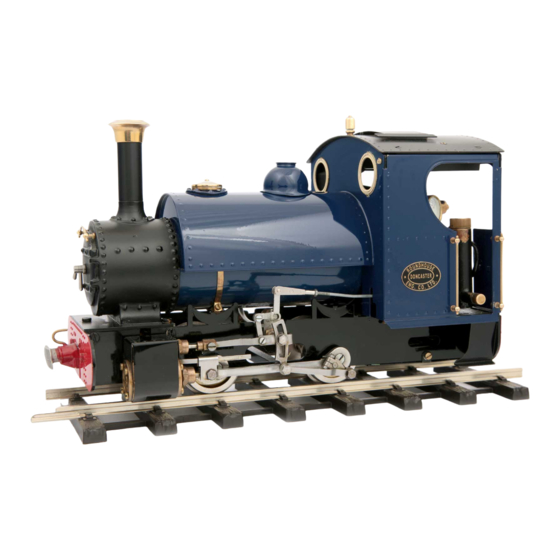
- Page 1 KATIE Owners Handbook For the Katie Locomotive...
-
Page 2: Safety Precautions
Operating Instructions IMPORTANT: Read these instructions carefully before operating the locomotive The following items are required for running this engine and are not included with the model. Fuel Butane gas. See ’Gas System’ section. Water See 'Filling the boiler' section. General Lubricating oil See 'Lubrication' section. - Page 3 Katie Instruction Booklet CONTENTS Tool kit. Page 4 Running in. Page 4 Access to the controls. Page 4 Identification of parts of the locomotive. Page 5 Preparing for operation. Page 6 1. Filling the Gas Tank. Page 6 2. Filling the Boiler.
-
Page 4: Access To The Controls
TOOL KIT The following items are included with your locomotive. One 60ml bottle of special steam oil for use in the cylinder lubricator. One Allen key for cylinder socket cap screws. One 60ml syringe with plastic tube for filling the boiler with water. One pair of protective gloves. -
Page 5: Identification Of Parts Of The Locomotive
IDENTIFICATION OF PARTS OF THE LOCOMOTIVE Radio controlled version illustrated 1) Lubricator drain screw. 2) Lubricator filler cap. 3) Reversing servo (this is a reversing lever on manual models). 4) Pressure gauge. 5) Safety valve 6) Gas regulator. 7) Gas filler valve. 8) Steam regulator. 9) Steam regulator servo and linkage (not on manual versions). -
Page 6: Preparing For Operation
A special brass gas filler adapter is obtainable from your local garden railway supplier or direct from ROUNDHOUSE. Mixed gasses are also available and may be used if ordinary butane or iso-butane are not available, but see the ‘Gas System’... - Page 7 needed when removing the dome, especially when the engine is hot, as the dome itself will be hot. Take care not to drop the dome onto the locomotive, as the weight of it may damage the model. Lift off the brass dome then remove the safety valve by unscrewing the large knurled plug into which it is fitted.
-
Page 8: Lighting The Burner
Tighten the drain screw and refill with the steam oil supplied, then replace the cap. Take time filling the lubricator, especially when cold, as the oil takes time to run down and may trap an air bubble. Both cap and drain screw are fitted with ‘0’ rings and need only be closed finger tight. -
Page 9: Running The Locomotive
ignite the burner correctly, then a dirty jet should be suspected and cleaned as detailed in the ‘troubleshooting’ scetion. For the first couple of minutes keep the burner on low. This is important, as until it warms up, the flame will be a little unstable and turning it up too much could cause it to go out. -
Page 10: Driving The Locomotive Manually
the loco comes to a halt. Should the water expire before the gas is fully used, the pressure will drop rapidly and the loco will stop. Check the pressure gauge – if this is zero turn off the gas. No damage will result if the gas is turned off immediately. -
Page 11: Driving By Radio Control
The art of fine control will soon be learnt with a little practice. DRIVING BY RADIO CONTROL This model is fitted with 2.4 GHz R/C equipment. On a Radio Controlled model, speed and direction are controlled by the transmitter. First, turn on the transmitter and then switch on the receiver on the locomotive with the switch on the right hand side of the chassis, just below the cab footplate. -
Page 12: Storage Between Operating Sessions
Always switch off the receiver and transmitter when not in use to preserve battery life. It is good practice to switch on the transmitter before the receiver and switch off the receiver before the transmitter. In this way, the radio receiver is never on when the transmitter is switched off and so should always be under your control. -
Page 13: Altering Wheel Gauge
ALTERING WHEEL GAUGE The wheels are set at the factory for the specified gauge however, for those who wish to alter this to run on other people’s railways or if you change the gauge of your track, they are easily reset with the aid of the back to back gauge supplied in the toolkit. -
Page 14: Radio Control
Control equipment, refer to the manufacturers literature supplied. GAS SYSTEM Katie locomotives are fitted with our 'FG' type gas burner, which is set up and fully tested at the factory. This system is designed for use with Butane or Iso-Butane gas. - Page 15 difficult to light when cold or after filling the gas tank. Always open the regulator very slowly when lighting, and only just sufficient for ignition to take place. Opening too much too soon may extinguish the flame until the burner reaches normal operating temperature. The tiny jet in these units can become blocked by small particles of dirt making the burner difficult to light, burn weakly at normal operating temperatures*, burn in the smokebox or fail completely.
- Page 16 ‘spongy’ in operation, making precise gas control difficult. As stated in the lighting instructions, the full range of adjustment for normal burner operation is achieved within the first full rotation of the regulator knob, and it should only be unscrewed more than this for maintenance purposes and when the tank is empty, and there are no naked lights nearby.
- Page 17 ROUNDH OUSE ENGINE ERING Model: Katie Serial No.: Description and specification of equipment covered Model: Type 1 boiler Serial No.: Test date: Steam Gen- erator and as- Vessel for Model: Serial No.: Group 1 gasses and Test date: associated pipe work and fittings.
- Page 18 Please refer to the ‘owners handbook’ for your particular model of locomotive, for details on correct use of these pressure vessels. Pressure vessel care and maintenance Gas tank The gas tank is used for the storage of LPG (liquefied petroleum gas) in the form of butane, iso-butane or as set out in the ‘owners handbook’.
- Page 19 Gas Burner 1). Superheater Pipe. 2). Lubricator Pipe. 3). Gas Jet Holder retaining screw. 4). Gas Jet. 5). Gas Jet Holder. 6). Gas Pipe. 7). Gas Burner fixing screw. 8). Air Inlet Holes.
-
Page 20: Service And Parts
Your dealer is; ROUNDHOUSE If your dealer is unable to help, please contact the Factory directly: ROUNDHOUSE ENGINEERING CO. LTD. Units 6-10 Churchill Business Park. Churchill Road. Wheatley. Doncaster. DN1 2TF. England Telephone: 01302 328035 Fax: 01302 761312 Email: mail@roundhouse-eng.com...
Need help?
Do you have a question about the Katie and is the answer not in the manual?
Questions and answers