Table of Contents
Advertisement
Quick Links
Advertisement
Table of Contents

Related Manuals for roundhouse TOM ROLT


Summary of Contents for roundhouse TOM ROLT
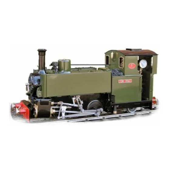
- Page 1 TOM ROLT Owners Handbook For the Tom Rolt Locomotive...
- Page 2 OPERATING INSTRUCTIONS IMPORTANT: Read these instructions carefully before operating the locomotive. The following items are required for running this engine and are not included with the model. Fuel Butane gas. See 'Filling the gas tank' Water See 'Filling the boiler' Lubricating oil See 'Lubrication' SAFETY PRECAUTIONS This is a working model locomotive using steam under pressure...
-
Page 3: Table Of Contents
Tom Rolt Instruction Booklet CONTENTS Tool kit. Page 4 Running in. Page 4 Access to the controls. Page 4 Replacing the Batteries. Page 5 Identification of parts of the locomotive. Page 6 Preparing for operation. Page 7 1. Filling the Gas Tank. -
Page 4: Tool Kit
TOOL KIT The following items are included with your locomotive. One 60ml bottle of special steam oil for use in the lubricator. One 60ml syringe & plastic tube for filling the boiler with water. One water top-up pump bottle. One set of spare washers and ‘0’ rings. One spare gas jet. -
Page 5: Replacing The Batteries
REPLACING THE BATTERIES The batteries on a model fitted with radio control are located beneath the right-hand side tank. To remove this and gain access to the batteries the side tank has to be removed. Lay the locomotive gently on its left side on a clean soft cloth, to avoid marking the paintwork. -
Page 6: Identification Of Parts Of The Locomotive
IDENTIFICATION OF PARTS OF THE LOCOMOTIVE Radio controlled version illustrated a) Safety Valve. b) Water Top-Up Valve. c) Pressure Gauge. d) Gas Filler Valve. e) Gas Tank. f) Gas Regulator. g) Steam Regulator. h) Gas Jet Holder. i) Water Gauge. j) Lubricator Drain Screw. -
Page 7: Preparing For Operation
A special brass gas filler adapter is obtainable from your local garden railway supplier or direct from ROUNDHOUSE. Mixed gasses are also available and may be used if ordinary butane or Iso-butane are not available, but see the ‘Gas System’... -
Page 8: 2B. Filling Using The Pump Bottle
completely off to access the safety valve. This dome is a substantial and heavy item, being turned from solid brass. Care is needed when removing the dome, especially when the engine is hot, as the dome itself will be hot. Take care not to drop the dome onto the locomotive, as the weight of it may damage the model. -
Page 9: Lubrication
3) LUBRICATION Regular lubrication of all working parts is important and should be carried out before each operating session. There are two types of lubrication required: The external moving linkages and bearings are lubricated with a medium oil such as motor engine oil, and the internal steam mechanisms such as cylinders, pistons and valves are lubricated with a special steam oil that is mixed with the steam. - Page 10 Move the locomotive to another location before lighting. Butane is heavier than air and small pockets of gas can collect around the locomotive during filling. To light the burner, hold a lighted match or cigarette lighter over the top of the chimney and slowly open the gas regulator by turning it anti-clockwise.
-
Page 11: Running The Locomotive
RUNNING THE LOCOMOTIVE When full working pressure has been reached (about 40psi), the safety valve will start to blow off steam. Steam generation can be controlled by the gas valve in the cab. If the safety valve blows off frequently during running, then too much steam is being produced, which wastes water and gas. - Page 12 3) The regulator. This is the main steam control valve and regulates the speed at which the engine will run. The regulator handle is situated in the right hand cab doorway and is moved anti-clockwise to open and clockwise to close. Using the reversing lever, select the desired direction of travel and open the regulator a little.
-
Page 13: Driving By Radio Control
DRIVING BY RADIO CONTROL This model is fitted with 2.4 GHz R/C equipment. On a Radio Controlled model, speed and direction are controlled by the transmitter. First, turn on the transmitter and then turn on the receiver using the switch on the locomotive. This is located on the right hand side of the locomotive, in the frame under the cab floor. -
Page 14: Water Top-Up System
ensure that the regulator is closed before switching off the transmitter. Always switch off the receiver and transmitter when not in use to preserve battery life. When the batteries are getting low, a poor signal between transmitter and receiver will result and control of the engine will become erratic. - Page 15 Push the end of the plastic tube into the socket in the top of the water filling valve. Whilst still holding the pipe in position and exerting slight downward pressure, pump the handle and this will inject water into the boiler. You will sometimes see water and air bubbles passing through the sight glass as you pump so allow the level to settle after a few pumps.
-
Page 16: Storage Between Operating Sessions
STORAGE BETWEEN OPERATING SESSIONS At the end of an operating session, it is good practice to clean the locomotive carefully with a clean soft cloth, and to oil all bright metal parts. Do not leave fuel or water in the tank or boiler for long ... - Page 17 The front and rear cylinder covers are fitted with gaskets and the valve chests with ’O’ rings. A little ‘bubbling’ of oil may sometimes occur around these and is quite normal; however, steam leaking past the gasket should be attended to. If ‘nipping up’...
-
Page 18: Regulator Not Shutting
GAS SYSTEM Tom Rolt locomotives are fitted with our 'FG' type gas burner, which is set up and fully tested at the factory. This system is designed for use with Butane or Iso-Butane gas. - Page 19 when lighting, and only just sufficient for ignition to take place. Opening too much too soon may extinguish the flame until the burner reaches normal operating temperature. The tiny jet in these units can become blocked by small particles of dirt making the burner difficult to light, burn weakly at normal operating temperatures*, burn in the smokebox or fail completely.
-
Page 20: Gas Regulator (Internal Parts)
As stated in the lighting instructions the full range of adjustment for normal burner operation is achieved within the first full rotation of the regulator knob, and it should only be unscrewed more than this for maintenance purposes and when the tank is empty, and there are no naked lights nearby. - Page 22 Please refer to the ‘owner’s handbook’ for your particular model of locomotive, for details on correct use of these pressure vessels. Pressure vessel care and maintenance Gas tank The gas tank is used for the storage of LPG (liquefied petroleum gas) in the form of butane, iso-butane or as set out in the ‘owners handbook’.
-
Page 23: Identification Of Gas Burner Parts
Gas Burner 1). Superheater Pipe. 2). Lubricator Pipe. 3). Gas Jet Holder retaining screw. 4). Gas Jet. 5). Gas Jet Holder. 6). Gas Pipe. 7). Gas Burner fixing screw. 8). Air Inlet Holes. -
Page 24: Service And Parts
Your dealer is; ROUNDHOUSE If your dealer is unable to help, you may contact the Factory directly ROUNDHOUSE ENGINEERING CO. LTD. Units 6-9 Churchill Business Park. Churchill Road. Wheatley. Doncaster. DN1 2TF. England Telephone 01302 328035 Fax 01302 761312 email mail@roundhouse-eng.com...
Need help?
Do you have a question about the TOM ROLT and is the answer not in the manual?
Questions and answers