Sign In
Upload
Download
Table of Contents
Contents
Add to my manuals
Delete from my manuals
Share
URL of this page:
HTML Link:
Bookmark this page
Add
Manual will be automatically added to "My Manuals"
Print this page
×
Bookmark added
×
Added to my manuals
Manuals
Brands
roundhouse Manuals
Toy
Linda
Owner's handbook manual
roundhouse Linda Owner's Handbook Manual
Hide thumbs
1
2
Table Of Contents
3
4
5
6
7
8
9
10
11
12
13
14
15
16
17
18
19
20
page
of
20
Go
/
20
Contents
Table of Contents
Troubleshooting
Bookmarks
Table of Contents
Table of Contents
Tool Kit
Identification of Parts of the Locomotive
1 Filling the Gas Tank
2 Filling the Boiler
4 Lighting the Burner
Running the Locomotive
Driving by Radio Control
Water Top-Up System
Trouble Shooting & Maintenance
Steam Leaks
Water Top up System
Service and Parts
Advertisement
Quick Links
Download this manual
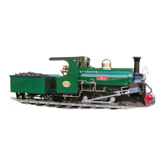
Linda, Blanche & Charles
Owners Handbook
For Linda, Blanche & Charles Locomotives
Table of
Contents
Previous
Page
Next
Page
1
2
3
4
5
Advertisement
Table of Contents
Need help?
Do you have a question about the Linda and is the answer not in the manual?
Ask a question
Questions and answers
Related Manuals for roundhouse Linda
Toy roundhouse Little John Owner's Handbook Manual
Diesel locomotive (9 pages)
Toy roundhouse LEEK & MANIFOLD Owner's Handbook Manual
(20 pages)
Toy roundhouse Katie Owner's Handbook Manual
Locomotive (21 pages)
Toy roundhouse ATLANTIC Owner's Handbook Manual
(20 pages)
Toy roundhouse Beddgelert 0-6-4 Owner's Handbook Manual
(24 pages)
Toy roundhouse Criccieth Castle Owner's Handbook Manual
(9 pages)
Toy roundhouse Carrie Owner's Handbook Manual
Locomotive (16 pages)
Toy roundhouse MILLIE Owner's Handbook Manual
Basic series locomotives (20 pages)
Toy roundhouse Mildred Owner's Handbook Manual
(20 pages)
Toy roundhouse TOM ROLT Owner's Handbook Manual
(24 pages)
Toy roundhouse Vale of Rheidol 2-6-2 Owner's Handbook Manual
(28 pages)
Toy roundhouse FOWLER Owner's Handbook Manual
(20 pages)
Toy roundhouse SR&RL 24 Owner's Handbook Manual
(20 pages)
Toy roundhouse Darjeeling ‘D’ Class Garratt Owner's Handbook Manual
(24 pages)
Toy roundhouse TALIESIN Owner's Handbook Manual
(24 pages)
Toy roundhouse RUSSELL Owner's Handbook Manual
(20 pages)
This manual is also suitable for:
Charles
Blanche
Table of Contents
Print
Rename the bookmark
Delete bookmark?
Delete from my manuals?
Login
Sign In
OR
Sign in with Facebook
Sign in with Google
Upload manual
Upload from disk
Upload from URL


Need help?
Do you have a question about the Linda and is the answer not in the manual?
Questions and answers