Advertisement
Quick Links
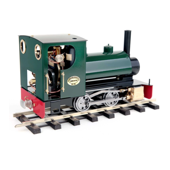
Modular Locomotive System
HBK18 Katie R/C Fittings
Note:- this kit contains the parts to enable radio control
equipment to be fitted to a 'Katie' locomotive. No radio control
equipment is included with this kit.
Roundhouse Engineering Co. Ltd.
Units 6-9 Churchill Business Park. Churchill Road,
Wheatley. Doncaster. DN1 2TF. England.
ONLINE
Only Kit
Instruction Manual
Tel.
01302 328035
Fax.
01302 761312
Email. support@roundhouse-eng.com
www.roundhouse-eng.com
1
Advertisement

Related Manuals for roundhouse HBK18 Katie R/C Fittings Only Kit


Summary of Contents for roundhouse HBK18 Katie R/C Fittings Only Kit
- Page 1 Note:- this kit contains the parts to enable radio control equipment to be fitted to a ‘Katie’ locomotive. No radio control equipment is included with this kit. Roundhouse Engineering Co. Ltd. Units 6-9 Churchill Business Park. Churchill Road, Wheatley. Doncaster. DN1 2TF. England.
- Page 2 It contains all necessary brackets, fixings etc. to enable the builder to fit his or her own radio equipment. Roundhouse ‘Katie’ locomotives are fitted as standard with 2.4 GHz two-channel radio control equipment and all fixings and brackets are designed for this. If using different equipment, ensure that it is of similar specification or problems could be encountered.
- Page 3 Construction Folding battery box and chassis cover plate. First of all, fold up the etched brass battery box and chassis cover plate as shown above and paint them as required. Note that all half etched fold lines should be to the inside of the fold. All painting is left to the builder and Acrylic paint is readily available in spray cans for a good finish.
- Page 4 The locomotive body should first be removed to allow installation of the radio control equipment. Reversing Servo 1 - Reversing servo-mounting posts. 2 - Reversing servo. 3 - Short servo horn. 4 - Reversing control rod. 5 - Quicklink connector. Fit the reversing servo that operates the Walschaerts valve- gear first.
- Page 5 mounting post with a plastic cable tie, and then passed down through the small rectangular hole to the left of the boiler. Do not fit the horn or linkage at this time. Regulator Servo 1 - Regulator arm. 2 - Push rod connector. 3 - Regulator control rod with Quicklink and lock nut.
- Page 6 the foot plate (which you fitted during the body construction). The servo is passed through the rectangular hole in the bracket from the rear with the lead to the top. The lead can then be passed down the front of the servo between it and the gas tank and through the rectangular hole in the footplate to the left of the servo.
- Page 7 connected together. Two short lengths of the small diameter shrink-wrap about ½" (13mm) long should be cut from the 2” (5 cm) piece supplied, to insulate the soldered joints. Shrink-wrap is a special rubber tube, which reduces in diameter when heated. To use it, first slide it over the end of one of the two wires to be joined then, after the wires are soldered together, slide it back to cover the exposed joint and overlap the insulation at little at each side.
- Page 8 Chassis Cover Plate Plug the regulator servo lead into channel 2 on the receiver and the reversing servo lead into channel 1. All loose wires, except the long battery wire can be tidied up using the cable ties supplied. Ensure that none are in contact with hot pipes or fittings and out of the way of any moving parts.
- Page 9 large flap fits up between the frames behind the rear wheels. When in place this cover boxes in the rear portion of the chassis - see picture on opposite page. Now that the main items are installed, we can fit and adjust the linkages, first however, the spring which self-centres the left hand (regulator) control arm on the transmitter needs removing.
- Page 10 Reversing Servo Push Rod Connection 1 - Starlock washer. 2 - Pushrod connector. 3 - Lock screw Fit a push rod connector as shown in diagram 5. Push the spigot through the hole from the front and push the Starlock washer over the spigot to lock it on.
- Page 11 screws. This has now set the servo horn for mid gear and moving the control lever either way will move the horn accordingly. Set up the transmitter, using the servo reversing switch if necessary, so that moving the lever to the left engages forward gear (moves horn forwards) and to the right engages reverse (moves servo horn to the rear).
- Page 12 A replacement r/c type regulator is supplied with this kit. Although externally it looks the same as the manual type supplied with the boiler kit, internally it is quite different. It is designed to operate with a servo where a small amount of movement must give full control from closed to fully open.
- Page 13 Regulator Push Rod Connector 1 - Clamp screw. 2 - Push rod connector. 3 - Starlock washer. Prepare a servo horn with a single arm and four connection holes. Fit the horn so that it is pointing to roughly half way between 8 and 9 on a clock face and fix it in place with the small screw provided.
- Page 14 supplied linkage, Quicklink and lock nut, connect the regulator arm to the servo horn as shown in diagram 3. First pass the plain end of the rod through the push rod connector on the regulator arm, and then clip the Quicklink in either the 2nd or 3rd hole on the servo horn.
- Page 15 This is because the '0' ring will compress slightly into its seat when fully closed. You may need to adjust the position of the arm on the spindle, the control rod in the push rod connector, or position of the Quicklink on the servo horn to achieve this. When satisfied that all is adjusted correctly, tighten all screws, switch off the gas burner and r/c equipment and disconnect battery clip.
- Page 16 Steam regulator with arm and 1 grub screw (r/c type) 18 cm length of large diameter shrink wrap 3 cm length of medium diameter shrink-wrap 5 cm length of small diameter shrink-wrap 8BA x 3/16" CSK. Screws and 2 x 8BA nuts Plastic cable ties. Checked www.roundhouse-eng.com...
Need help?
Do you have a question about the HBK18 Katie R/C Fittings Only Kit and is the answer not in the manual?
Questions and answers