
Related Manuals for roundhouse Vale of Rheidol 2-6-2


Summary of Contents for roundhouse Vale of Rheidol 2-6-2
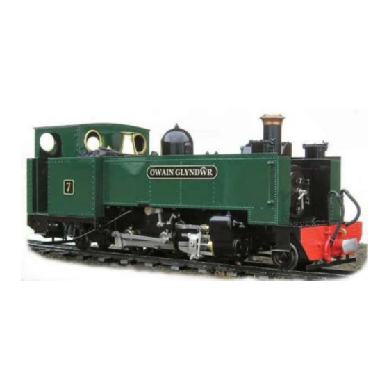
- Page 1 Vale of Rheidol 2-6-2 Owners Handbook For the Vale of Rheidol 2-6-2 tank Locomotive...
-
Page 2: Operating Instructions
Operating Instructions IMPORTANT: Read these instructions carefully before operating the locomotive The following items are required for running this engine and are not included with the model. Fuel Butane gas. See ’Gas System’ on page 21 Water See 'Filling the boiler' on page 9 General Lubricating oil See 'Lubrication' on page 10 SAFETY PRECAUTIONS This is a working model locomotive using steam under pressure... -
Page 3: Table Of Contents
VoR Instruction Booklet CONTENTS Tool kit & Un-packing the model Page 4 Running in Page 6 Access to controls Page 6 Identification of parts of the locomotive Page 7 Preparing for operation Page 8 1. Filling the Gas Tank Page 8 2. -
Page 4: Tool Kit & Un-Packing The Model
TOOL KIT The following items are included with your locomotive. One 60ml bottle of special steam oil for use in the cylinder lubricator. One 60ml syringe with plastic tube for filling the boiler with water. One water top up pump bottle. One gas filling adapter. - Page 5 4) A set of dummy brake pipes are supplied and you will need to decide which, if any, you would like to fit. The fitment of them prototype locomotives varied over the years and if you require your model to represent a particular locomotive or era, check which pipes it carried.
-
Page 6: Running In
smear of ‘Devcon’ or similar, epoxy adhesive and the plate should be held in position with Sellotape until the adhesive has fully cured. As the positioning of the plates on the locomotives varied over the years, you should check with pictures or reference books for the particular era you wish to depict. -
Page 7: Identification Of Parts Of The Locomotive
IDENTIFICATION OF PARTS OF THE LOCOMOTIVE... -
Page 8: Preparing For Operation
PREPARING FOR OPERATION The locomotive must be serviced before being operated. It is important to perform all the following operations. NOTE, check that the batteries in both the R/C transmitter and the locomotive are in good condition before attempting to operate the model - see the Radio Control section later on. -
Page 9: Filling The Boiler
2) FILLING THE BOILER There are two methods of filling the boiler 1/ Quick filling when cold. The dummy steam dome on top of the boiler can be lifted completely off to access the filler plug. The dome is a substantial and heavy item, being machined from solid brass. -
Page 10: Lubrication
Pump the handle on the bottle to inject water into the boiler whilst maintaining this downward pressure. Keep pumping until the water level in the water gauge is almost at the top of the glass. Remove the plastic tube and replace the brass plug in the top of the dome. -
Page 11: Lighting The Burner
4) LIGHTING THE BURNER WARNING: Before lighting read the section on the gas system under Troubleshooting later on and be aware of potential problems. If the gas system is not operating correctly, shut it off immediately or damage may result. Move the locomotive to another location before lighting. -
Page 12: Running The Locomotive
RUNNING THE LOCOMOTIVE When full working pressure has been reached (between 35 and 40psi), the safety valve will start to blow off steam. Steam generation can be controlled by the gas valve in the right hand cab doorway. If the safety valve blows off frequently during running, then too much steam is being produced, which wastes water and gas. -
Page 13: Radio Control System
RADIO CONTROL SYSTEM The locomotive is operated by a four channel radio control system. There are two main control levers on the radio transmitter, each of which is bi-directional and controls two functions. Speed and direction are controlled by the left hand lever. Left to right for forward or reverse (mid gear in the centre position) and up and down for regulator open or close. -
Page 14: Driving The Locomotive
up at the front and then ease forward, taking care to hold onto the weight that is located in the front of the side tank. Batteries can now be fitted into the battery holder. The side tank can now be replaced. Hold the side tank as shown in the picture above. - Page 15 if fitted, by moving the right hand control lever fully over to the left. This will direct all exhaust out of the two pipes, facing forward, below the cylinders Select the desired direction of travel by moving the left hand lever fully over to either the left for forward or the right for reverse, and then slowly open the regulator a little by moving the left hand lever upwards.
-
Page 16: Water Top-Up System
simple reversing valve gear and is not capable for 'notching up' (altering the valve cut off). Always bring the locomotive to a halt by closing the regulator before changing direction. Always ensure that the regulator is closed and the reversing lever is in the middle position (mid gear) before switching off the transmitter. - Page 17 valve. Whilst still holding the pipe in position and exerting slight downward pressure, pump the handle and this will inject water into the boiler. You will sometimes see water and air bubbles passing through the sight glass as you pump so allow the level to settle after a few pumps.
-
Page 18: Steam Whistle
Once you start running your loco you will see the water level in the gauge slowly dropping. Note that air bubbles may sometimes form in the gauge giving a false reading but these can be pushed out by connecting the pipe from the water pump to the water filling connector –... -
Page 19: Storage Between Operating Sessions
STORAGE BETWEEN OPERATING SESSIONS At the end of an operating session, it is good practice to clean the locomotive carefully with a clean soft cloth, and to oil all bright metal parts. Do not leave fuel or water in the tank or boiler for long ... - Page 20 Inside the side tanks. Right hand side. radio control on/off switch. reversing servo. receiver. Left hand side. batteries. whistle valve servo.
-
Page 21: Regulator Not Shutting
Remove the dummy cylinder cover by springing it gently outwards from the bottom then lifting the top off the back side of the valve chest. You will now see the four countersunk brass screws that fix the valve chest to the cylinder block. Carefully ‘nip’ these down. There are access holes in the side tank base panels above, for access to the inside screws but it may be necessary to remove the battery pack or receiver first. -
Page 22: Gas System
The radio control system is carefully set up during assembly of the locomotive. Do not alter any of the factory settings and ensure all trimmers are in the correct position as detailed in the Radio Control System section earlier. If problems occur whilst running the locomotive near other R/C engines, check that yours is on a different frequency. - Page 23 2BA spanner. Note when connecting or disconnecting the gas pipe and gas jet holder, do not use excessive force. Always hold the end of the gas burner near the air holes to support it otherwise it is possible to cause damage by bending the body. Slacken the screw retaining the gas jet holder and slide it out to the rear.
-
Page 24: Water Top-Up System
The ‘O’ ring can now be lubricated. Replace the spindle followed by the retaining nut. Slide the backlash spring over the spindle and replace the knob. Note that the grub screw that holds the knob in place tightens into a groove near the end of the spindle and should be in a position that allows the side handle to be screwed in and operate the regulator without fouling other controls or the cab side. -
Page 25: Boiler And Gas Tank Certificate, Pages 25
Fax 01302 761312 www.roundhouse-eng.com EC Declaration Of Conformity I hereby declare that the model described: Model: Vale of Rheidol 2-6-2 Serial No.: Conforms to the Pressure Equipment Directive 97/23/EC All components and assemblies have been designed and manufactured according to sound engineering practice (SEP) - Page 26 Please refer to the ‘owner’s handbook’ for your particular model of locomotive, for details on correct use of these pressure vessels. Pressure vessel care and maintenance Gas tank The gas tank is used for the storage of LPG (liquefied petroleum gas) in the form of butane, iso-butane or as set out in the ‘owners handbook’.
- Page 27 Gas Burner 1). Superheater Pipe. 2). Lubricator Pipe. 3). Gas Jet Holder retaining screw. 4). Gas Jet. 5). Gas Jet Holder. 6). Gas Pipe. 7). Gas Burner fixing screw. 8). Air Inlet Holes.
- Page 28 Your dealer is; ROUNDHOUSE If your dealer is unable to help, you may contact the Factory directly: ROUNDHOUSE ENGINEERING CO. LTD. Units 6-9 Churchill Business Park. Churchill Road. Wheatley. Doncaster. DN1 2TF. England Telephone 01302 328035 Fax 01302 761312 e-email support@roundhouse-eng.com...
Need help?
Do you have a question about the Vale of Rheidol 2-6-2 and is the answer not in the manual?
Questions and answers