Table of Contents
Advertisement
Quick Links
(For microscope operation only. Camera operation and installation covered in separate
1. Microscope serial number: This number (etched on back arm of microscope) is the
number under which your warranty is registered.
2. Microscope DM number: This number (found on a white sticker on the bottom of the
microscope) is used for logging on the Motic web site, which gives you the ability to
download free software upgrades.
3. Motic CD DM number: This number is to be used to register the software when
loaded on the computer for the first time.
Copyright © 8/5/04
National Optical & Scientific Instrument Inc.
National Optical & Scientific Instruments Inc.
11113 Landmark 35 Drive
San Antonio, Texas 78233
Phone (210) 590-9010
INSTRUCTIONS FOR
COMPOUND BIOLOGICAL MICROSCOPE
WITH DIGITAL CAMERA
supplement to documentation)
HOW TO USE YOUR MICROSCOPE SERIAL NUMBERS
Fax (210) 590-1104
MODEL DC5-163
Advertisement
Table of Contents

Subscribe to Our Youtube Channel
Related Manuals for National DC5-163


Summary of Contents for National DC5-163
- Page 1 National Optical & Scientific Instruments Inc. 11113 Landmark 35 Drive San Antonio, Texas 78233 Phone (210) 590-9010 Fax (210) 590-1104 INSTRUCTIONS FOR MODEL DC5-163 COMPOUND BIOLOGICAL MICROSCOPE WITH DIGITAL CAMERA (For microscope operation only. Camera operation and installation covered in separate...
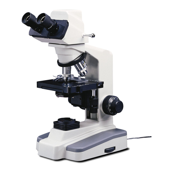
- Page 2 Eyepiece LED indicator light Sliding interpupillary adjustment grips located on both left and right side of diopter scale Interpupillary scale Three position sliding rod Viewing head of Mark on side of eyepiece tube microscope for indexing diopter reading Revolving nosepiece Objective lenses Knurled locking screws for securing specimen...
- Page 3 About the Digital Microscope The manual for your new digital microscope is in three parts. This first part describes the basic nomenclature and functions of the microscope, which can be used as a fully functional microscope, independent of the camera. The second part is the “Important Supplement to Documentation”...
-
Page 4: Operation
ASSEMBLY 1. Specimen holder: Rotate coarse focusing knob to move stage platform to its lowest position. Remove two knurled screws from mechanical stage platform. Place specimen holder on stage and using the two knurled locking screws, attach holder to mechanical stage. 2. - Page 5 C. Flip power switch located on back of microscope base “ON”. Note that LED indicator will not light until USB cable is connected to computer, when instructed in separate Quick Start Guide located on your CD. D. Rotate intensity dial on illuminator base until image is illuminated. E.
- Page 6 Iris diaphragm should not be used to control the brightness of illumination. Iris diaphragms are designed to help achieve high resolution of specimen and provide contrast in the image. Smaller apertures will deliver higher contrast to image. However, closing aperture too much will reduce resolution. Experimentation is the best method of determining the correct opening of diaphragm.
-
Page 7: Mechanical Maintenance
MAINTENANCE WARNING: FOR YOUR SAFETY, TURN SWITCH OFF AND REMOVE PLUG FROM POWER SOURCE OUTLET BEFORE MAINTAINING YOUR MICROSCOPE. TO AVOID SHOCK OR FIRE HAZARD, IF POWER CORD IS WORN, CUT OR DAMAGED IN ANY WAY, HAVE IT REPLACED AT ONCE. 1. -
Page 8: Troubleshooting
a) Carefully lay instrument on its side, taking care to avoid damage to the specimen slide holder located on top of mechanical stage. b) Loosen large chrome locking screw located on hinged door of illuminator base. c) Swing door open to expose the halogen lamp. d) Using a tissue or cloth to gently grasp the halogen bulb, pull straight out of lamp socket. -
Page 9: Limited Lifetime Warranty
LIMITED LIFETIME WARRANTY National warrants this microscope to be free from defects in material and workmanship under normal use and service for the life of the instrument. The warranty does not cover damage resulting from abuse or misuse, repairs or alterations performed by other than authorized repair technicians, or damage occurring in transit. - Page 10 IMPORTANT SUPPLEMENT TO DOCUMENTATION FOR MOTICAM 1000 / MOTICAM 2000 (DC4-155, DC4-156-S, DC4-456H, DC4-410): MC1000 (DC5-163, DC5-420 ) : MC2000 Contents of this brochure covers certain enhancements to the software that are not covered in the original documentation that is included on the software CD “Quick Start Guide” manual, as well as additional trouble shooting procedures.
- Page 11 1. The Moticam 1000 and 2000 have very unique capture windows and it is important first to make sure that this capture window is being used by default. • First click on file at the top left hand side of the Motic Images software. The file menu will drop. •...
- Page 12 SD-NECUSB20-031001 NEC PCI USB 2.0 U s e r M a n u a l For use with Moticam 1000, Moticam 2000, DC4 and DC5 Series Introduction This NEC PCI to USB 2.0 Host Controller card is compliant with the Universal Serial Bus Specification Revision 2.0 and Open Host Controller Interface Specification for low-speed (1.5Mbps) / full-speed (12Mbps) speed signaling and Enhanced Host Controller Interface Specification for high-speed signaling (480Mbps).
Need help?
Do you have a question about the DC5-163 and is the answer not in the manual?
Questions and answers