Table of Contents
Advertisement
Quick Links
Advertisement
Table of Contents

Related Manuals for National 160 SERIES


Summary of Contents for National 160 SERIES
- Page 1 National Optical & Scientific Instruments Inc. 11113 Landmark 35 Drive San Antonio, Texas 78233 Phone (210) 590-9010 Fax (210) 590-1104 INSTRUCTIONS FOR 160 SERIES COMPOUND BIOLOGICAL MICROSCOPES Copyright © 1/2/01 National Optical & Scientific Instrument Inc.
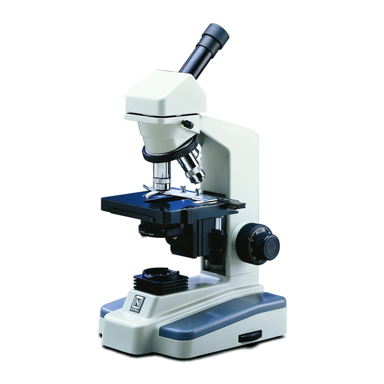
- Page 2 Models 160 (monocular head), 161 (dual head), 162 (binocular head), 163 (trinocular head), all have the same stand and stand features…only the head portion differs…illustrated is Model 162. Knurled diopter ring Sliding interpupillary adjustment, grips located on both left and right side of diopter scale Widefield 10x/18 eyepiece...
- Page 3 INTRODUCTION Thank you for your purchase of a National microscope. It is a well built, precision instrument carefully checked to assure that it reaches you in good condition. It is designed for ease of operation and years of carefree use. The information in this manual probably far exceeds what you will need to know in order to operate and maintain your microscope.
- Page 4 4. Remove block (c) from stand. 5. These components should be retained with styrofoam container Carefully remove from the stand all tape and packing material used to protect microscope components during shipment. For models 160, 161 and 162, lay container (B) flat and carefully remove head, eyepieces, rubber eyeshields, vertical eyepiece tube (model 161 only), four objectives, condenser, specimen holder, filters, fuse and dust cover.
-
Page 5: Operation
Heads: Mounting the head to stand. Loosen knurled head locking screw. Insert viewing head into stand by inserting head flange into receiving flange on arm of microscope. Lower the head until fully seated on top of arm. Position head so that it faces either forward or backward, whichever suits your preference or needs, and tighten knurled head locking screw. - Page 6 When a full field of view is observed through both tubes, and images blend into one, interpupillary distance is corrected for your eyes. Check the interpupillary scale and note index reading for future reference, in case other users will be changing this adjustment from time to time. Adjust the diopter scales, located on each eyepiece tube, to the same numerical value as indicated on the interpupillary scale.
- Page 7 All air bubbles must be removed from between lens and slide by rotating nosepiece back and forth. Objective Specification Chart Objective N.A. Color Code Ring Field of View Magnification Din 4X 0.10 4.5mm Din 10X 0.25 Yellow 1.8mm 100X Din 40X 0.65 Blue 0.45mm...
- Page 8 With camera and monitor on, slowly rotate the knurled diopter on “C” adapter until image is in focus on monitor. If microscope image, as viewed on TV monitor does not remain in focus when microscope magnification is changed, recheck CCTV camera chip size. Perhaps it will be necessary to either replace or remove the top “CS”...
-
Page 9: Maintenance
C. To mount CCTV camera, optional accessory #930-005 video adaptor (d.) is required. This adaptor has an 0.5x lens which assures image parfocality when viewed through a video monitor. Observe that video adaptor has two black knurled rings. If your CCTV camera has a 1/2 inch chip, leave both knurled rings in place, thereby creating a “CS”... -
Page 10: Electrical Maintenance
Carefully clean lamp to assure that it is clean and free of all fingerprints. Close hinged door and tighten locking screw. Replacement of fuse (National #801-160). The fuse is located at right rear side of microscope base. To remove fuse from holder, insert a 6mm screwdriver blade into slot located in rear of fuse cap. -
Page 11: Troubleshooting
VII. TROUBLESHOOTING ELECTRICAL PROBLEM REASON FOR PROBLEM SOLUTION Light fails to operate Outlet inoperative. Have qualified service technician repair outlet AC power cord not connected. Plug into outlet. Lamp burned out. Replace lamp. Fuse burned out. Replace fuse. Fuse burns out too soon. Replace with proper fuse (Time delay). -
Page 12: Optional Accessories And Parts
This warranty gives you specific legal rights, and you may also have other rights that vary from state to state. If you have questions concerning this product or warranty, contact the dealer from which it was purchased. You may also contact National at the address or phone number on the cover of this manual and ask for warranty assistance. (Revised 8/26/08)
Need help?
Do you have a question about the 160 SERIES and is the answer not in the manual?
Questions and answers