Yamaha M7CL-32 Service Manual
M7cl series digital mixing console
Hide thumbs
Also See for M7CL-32:
- User manual (16 pages) ,
- Owner's manual (312 pages) ,
- Quick start manual (19 pages)
Table of Contents
Advertisement
Quick Links
• M7CL-32
• M7CL-48
OptION
MBM7CL
POWER SUPPLY LINK CABLE
PSL360
CONTENTS
LSI PIN DESCRIPTION
IC BLOCK DIAGRAM
.................................. 118/122
PA
011804
M7CL-32: 20051101-2250000
M7Cl-48: 20051101-2750000
MBM7CL: 20051101-130000
PSL360:
20051101-
DIGITAL MIXING CONSOLE
................................... 5
................................ 10
................... 11
......................................... 17
........................................... 19
............ 24
.............. 52
................... 62
........................ 67
......................... 126/140
............................. 154
.................. 155/156
............... 157/173
SERVICE MANUAL
INITIALIZING THE M7CL's INTERNAL MEMORY
Midi Implementation Chart ....................... 201
Midi Data Format .......................................... 202
MBM7CL PARTS LIST
MBM7CL BLOCK DIAGRAM
MBM7CL CIRCUIT DIAGRAM
PSL360 PARTS LIST
Copyright (c) Yamaha Corporation. All rights reserved. PDF
M7CL-48/MBM7CL
........ 189/190
......................... 191/194
............... 197/199
HAMAMATSU, JAPAN
1
'05.11
Advertisement
Table of Contents

Related Manuals for Yamaha M7CL-32


Summary of Contents for Yamaha M7CL-32
- Page 1 MBM7CL BLOCK DIAGRAM ......154 MBM7CL CIRCUIT DIAGRAM INSTALLING an OPTION CARD PSL360 PARTS LIST ....155/156 USER SETTINGS (SECURITY) ....157/173 011804 M7CL-32: 20051101-2250000 HAMAMATSU, JAPAN M7CL-48: 20051101-2750000 MBM7CL: 20051101-130000 Copyright (c) Yamaha Corporation. All rights reserved. PDF ’05.11 PSL360: 20051101-...
-
Page 2: Important Notice
IMPORTANT NOTICE This manual has been provided for the use of authorized Yamaha Retailers and their service personnel. It has been assumed that basic service procedures inherent to the industry, and more specifically Yamaha Products, are already known and understood by the users, and have therefore not been restated. -
Page 3: Backup Battery
M7CL-32/M7CL-48 IMPORTANT NOTICE FOR THE UNITED KINGDOM Connecting the Plug and Cord WARNING: THIS APPARATUS MUST BE EARTHED IMPORTANT. The wires in this mains lead are coloured in accordance with the following code: GREEN-AND-YELLOW : EARTH BLUE : NEUTRAL BROWN... - Page 4 M7CL-32/M7CL-48 M7CL-32 M7CL-48 MBM7CL (Option)
-
Page 5: Specifications
–82 dBu –62 dBu –42 dBu –62 dB 50-600 Ω Mics (61.6 µV) (0.616 mV) (6.16 mV) XLR-3-31 type INPUT 1-32 <M7CL-32> 3 kΩ & INPUT 1-48 <M7CL-48> (Balanced) 600 Ω Lines –10 dBu +10 dBu +30 dBu +10 dB (245 mV) (2.45 V) -
Page 6: Analog Output Characteristics
M7CL-32/M7CL-48 • Analog Output Characteristics Output Level Actual Source For Use With Output Terminals GAIN SW Connector Impedance Nominal Nominal Max. Before Clip +24 dB (default) +4 dBu (1.23 V) +24 dBu (12.28 V) XLR-3-32 type 75 Ω 600 Ω Lines... -
Page 7: Electrical Characteristics
Fs= 44.1 kHz or 48 kHz @ 20 Hz–20 kHz, referenced to the nominal output level @1 kHz Input Output Conditions Min. Typ. Max. Unit 600 Ω OMNI OUT 1-16 –1.5 INPUT 1-32 <M7CL-32> GAIN: Max. 8 Ω INPUT 1-48 <M7CL-48> PHONES –3.0 600 Ω OMNI OUT 1-16 –1.5 ST IN 1-4 [L, R] GAIN: Max. -
Page 8: Sampling Frequency
Output Conditions Min. Typ. Max. Unit Input Level : –62 dBu, GAIN: Max. INPUT 1-32 <M7CL-32> 600 Ω OMNI OUT 1-16 Input Level : +10 dBu, GAIN: Min. INPUT 1-48 <M7CL-48> Input Level : –62 dBu, GAIN: Max. 600 Ω... -
Page 9: Other Functions
M7CL-32/M7CL-48 4. Other Functions • Libraries • Output Function Name Number Total Function Parameter Scene Memory Preset 1 + User 300 Attenuator –96 to +24 dB Input EQ Library Preset 40 + User 159 Frequency= 20 Hz to 20 kHz... -
Page 10: Connector Pin Assignments
M7CL-32/M7CL-48 • MBM7CL 442 x 103 x 36 mm 442 x 103 x 36 mm Dimensions (W x H x D) (W x H x D) Weight 1.0 kg 1.0 kg Package Contents Cable cover, Owner's Manual CONNECTOR PIN ASSIGNMENTS •... -
Page 11: Panel Layout
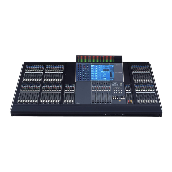
M7CL-32/M7CL-48 PANEL LAYOUT 1. Top Panel * This illustration shows the top panel of the M7CL-48. The M7CL-32 does not have the INPUT section at the right (channels 33–48). q INPUT section: ( P.13) w ST IN (Stereo Input) section: ( P.13) - Page 12 M7CL-48 only o i u yt e M7CL-48 only * This illustration shows the rear panel of the M7CL-48. q INPUT jacks 1-32 (M7CL-32) INPUT jacks 1-48 (M7CL-48) w ST IN jacks 1-4 e LAMP connector r OMNI OUT jacks 1-16...
- Page 13 M7CL-32/M7CL-48 4. Top Panel Details 4-1 INPUT section 4-2 ST IN (Stereo Input) section q [SEL] key w [CUE] key e Meter LEDs r [ON] key t Fader 4-3 Meter bridge (option) q MIX meters w MATRIX meters...
- Page 14 M7CL-32/M7CL-48 4-4 SELECTED CHANNEL section q [MIX/MATRIX] encoders w [HA] encoder e [PAN] encoder r [DYNAMICS 1] encoder t [DYNAMICS 2] encoder y [HPF] encoder u EQ [Q], EQ [FREQUENCY], EQ [GAIN] encoders 4-5 Display section q Display (touch screen)
- Page 15 M7CL-32/M7CL-48 4-6 Centralogic section q Multi-function encoders w [SEL] key e [CUE] key r Meter LEDs t [ON] key y Fader 4-7 SCENE MEMORY/MONITOR section q SCENE MEMORY [STORE] key w SCENE MEMORY [RECALL] key e SCENE MEMORY [ ] keys...
- Page 16 M7CL-32/M7CL-48 4-8 USER DEFINED KEYS section 4-9 STEREO/MONO MASTER section q User defined keys [1]-[12] 4-10 NAVIGATION KEYS section q [SEL] key w [CUE] key e [ON] key !0 !1 r Fader q [IN 1-8] key w [IN 9-16] key...
- Page 17 M7CL-32/M7CL-48 DIMENSIONS • M7CL-32 955: PSL360 (option) 340:MBM7CL (option) Units: mm 1060...
- Page 18 M7CL-32/M7CL-48 • M7CL-48 955: PSL360 (option) 340:MBM7CL (option) 1026 Units: mm 1274...
-
Page 19: Circuit Board Layout
M7CL-32/M7CL-48 CIRCUIT BOARD LAYOUT Control panel 2 assembly: M7CL-32 See page 22. Control panel 1 assembly 32: See page 22. LCD assembly 32: See page 23. Bottom assembly 32: See page 20. M7CL-48 Control panel 2 assembly: See page 22. - Page 20 M7CL-32/M7CL-48 M7CL-32 Bottom assembly 32 Power supply assembly HAAD ST IN Cannon connector HAAD CH 1-4 INPUT CH 1-8 HAAD AC inlet INPUT CH 9-16 Power supply unit DC fan motor HAAD INPUT CH 17-24 HAAD INPUT CH 25-32 OMNI OUT...
- Page 21 M7CL-32/M7CL-48 M7CL-48 Bottom assembly 48 Power supply assembly HAAD ST IN CH 1-4 HAAD Cannon connector INPUT CH 1-8 HAAD INPUT AC inlet DC fan motor CH 9-16 Power supply unit Receptacle assembly HAAD INPUT CH 17-24 HAAD INPUT CH 25-32...
- Page 22 M7CL-32/M7CL-48 M7CL-32 Control panel 1 assembly 32 M7CL-48 Control panel 1 assembly 48 <Bottom view> PNMS8 PNMS2 FDMS2 NAV32 (M7CL-32) NAV48 (M7CL-48) PNMS4 FDMS8 FDMS4 Control panel 2 assembly PNIN <Bottom view> CH 25-32 FDIN CH 25-32 PNIN CH 9-16...
- Page 23 M7CL-32/M7CL-48 Control panel 3 assembly (M7CL-48 only) <Bottom view> FDIN CH 41-48 FDIN CH 33-40 PNIN CH 41-48 PNIN CH 33-40 M7CL-32 LCD assembly 32 M7CL-48 LCD assembly 48 <Bottom view> CPUP DC-AC inverter Touch panel assembly USBIF MBM7CL (Option)
- Page 24 ..25 Control Panel 1 Assembly 32 (M7CL-32), Control Panel 1 Assembly 48 (M7CL-48) ..........27 Control Panel 2 Assembly .
- Page 25 ............... . 42 D-6. NAV32+PNMS8 Circuit Board (M7CL-32), NAV48+PNMS8 Circuit Board (M7CL-48) .
- Page 26 M7CL-32/M7CL-48 M7CL-48 <Left side view> <Top view> Control panel 1 assembly 48 <Right side view> 1 Ass'y 48 Control panel 2 assembly Control panel 3 assembly 2 Ass'y [22B] [12B] [12B] [32A] 3 Ass'y [1370A] [1370B] [32A] [22B] [1320A] [1320B]...
- Page 27 Control Panel 1 Assembly 32 (M7CL-32), Control Panel 1 Assembly 48 (M7CL-48) (Time required: About 4 minutes) Remove the front plate. (See procedure 1) M7CL-32: Remove the four teen (14) screws marked [12A]. (Fig.1-1) M7CL-48: Remove the four teen (14) screws marked [12B]. (Fig.1-2)
- Page 28 Remove the control panel 3 assembly. (M7CL-48 only) (See procedure 4) Remove the side pads L and R. (See procedure 5) M7CL-32: Remove the six (6) screws marked [960A] and loosen the two (2) screws mar ked [960B]. Lift the front pad assembly 32 a little and remove it.
- Page 29 M7CL-32/M7CL-48 Wood Panel L, R (Time required: About 1 minute each) Wood Panel L: 7-1-1 Remove the six (6) screws marked [1370A]. The wood panel L can then be removed. (Fig.1-1, Fig.1-2) Wood Panel R: 7-2-1 Remove the six (6) screws marked [1370B]. The wood panel R can then be removed.
- Page 30 (Fig.5) MAC (Media Access Control) address is stored in the CPUM circuit board assembly. If the CPUM Receptacle assembly ∗ The M7CL-32 does Ass'y circuit board assembly is replaced, MAC not have this section. address will be changed.
- Page 31 A-3-4 Remove the seven (7) screws marked [1010], the two (2) spacers marked [1020] and the spacer marked [1030]. (Fig.5) A-3-5 M7CL-32: Remove the DSP32 circuit board. (Fig.5) M7CL-48: Remove the DSP48 circuit board. (Fig.5) A-4. JK Circuit Board (Time required: About 5 minutes) A-4-1 Remove the front plate.
- Page 32 A-7-2 Fix the control panel 1 assembly. (See procedure 2) A-7-3 Remove the seven (7) screws marked [210A] and the screw marked [220A]. The DC circuit board can then be removed. (Fig.5) M7CL-48 (1/2) [460] ∗ The M7CL-32 does not have this section. [550A] M7CL-32 [550B] [550B] (2/2) [1190]...
- Page 33 M7CL-32/M7CL-48 A-8. Receptacle Assembly (Time required: About 5 minutes) A-8-1 Remove the front plate. (See procedure 1) A-8-2 Fix the control panel 1 assembly. (See procedure 2) A-8-3 Remove the four (4) screws marked [260A] and the screw marked [270A]. The receptacle assembly can then be removed.
- Page 34 M7CL-32/M7CL-48 Power Supply Assembly <Rigt side view> <Left side view> <Top view> AC case PW fan case [180] [260B] [180] DC fan motor <Left side view> AC inlet assembly [50] <Rigt side view> [130] PW fan case Fan case Fan folder...
- Page 35 M7CL-32/M7CL-48 Power switch knob Photo 8 Removing the DC fan motor Fan holder (4 pcs.) DC fan motor Fan case Photo 9 A-11. DCMS Circuit Board (Time required: About 6 minutes) A-11-1 Remove the front plate. (See procedure 1) A-11-2 Fix the control panel 1 assembly. (See procedure 2) A-11-3 Remove the large knob marked [1190] and the large knob marked [1195] from the front side.
- Page 36 M7CL-32/M7CL-48 B. Disassembly Procedure of Bottom Assembly section underneath Control Panel 2 Assembly B-1. Cannon Connector (Time required: About 4 minutes) B-1-1 Remove the front plate. (See procedure 1) B-1-2 Fix the control panel 2 assembly. (See procedure 3) B-1-3 Remove the two (2) screws marked [860A]. The Cannon connector can then be removed.
- Page 37 M7CL-32/M7CL-48 ∗ The M7CL-32 does not have this section. M7CL-32 M7CL-48 Cannon connector <Top view> HAAD HAAD (1/5) (3/5) [760A] [760C] [920A] [920B] [920A] [920B] DCIN DCIN (1/2) (2/2) HAAD (3/5) [750D] x 16 Cannon connector <Rear view> [860A] [750C] x 16...
- Page 38 M7CL-32/M7CL-48 B-3. DCIN (1/2, 2/2) Circuit Boards (Time required : About 5 minutes each) B-3-1 Remove the front plate. (See procedure 1) B-3-2 Fix the control panel 2 assembly. (See procedure 3) B-3-3 DCIN (1/2) Circuit Board: B-3-3-1Remove the six (6) screws marked [920A]. The DCIN (1/2) circuit board can then be removed.
- Page 39 M7CL-32/M7CL-48 M7CL-48 Ferrite core Cannon connector <Top view> HAAD (1/2) [760F] [920C] DCIN [920C] <Rear view> Cannon connector [860B] [750F] x 16 HAAD (1/2) HAAD (2/2) [750G] x 16 ∗ This figure shows the M7CL-48. M7CL-48 [750]: Bind Head Tapping Screw-B 2.6X8 MFZN2B3 (WE961700)
- Page 40 M7CL-32/M7CL-48 C-2-5 HAAD (2/2) Circuit Board (Time required: About 10 minutes): C-2-5-1Remove the HAAD (1/2) circuit board. (See procedure C-2-4) C-2-5-2Remove the sixteen (16) screws marked [750G] and two (2) screws marked [760G]. The HAAD (2/2) circuit board can then be removed. (Fig.11, 12)
-
Page 41: Rear/Bottom/Top View
M7CL-32/M7CL-48 <Rear view> MBM7CL [92B] [92A] [92A] [92B] M7CL [62A] Cable cover [62A]: Bind Head Screw 4.0X6 MFZN2B3 (WE878400) [92]: Bind Head Screw 4.0X6 MFZN2B3 (WE878400) Fig.13 FDMS4 [92D] x 4 <Bottom view> <Bottom view> [22C] [82] x 9 [92C]... - Page 42 M7CL-32/M7CL-48 D-2. LCD Assembly (Time required: About 6 minutes) D-2-1 Remove the MBM7CL. (See procedure D-1) D-2-2 Remove the front plate. (See procedure 1) D-2-3 Fix the control panel 1 assembly. (See procedure 2) D-2-4 Remove the seven (7) screws marked [22C] and loosen the two (2) screws marked [92C].
- Page 43 M7CL-48: Remove the NAV48+PNMS8 circuit board. (Fig.14) The NAV48 circuit board and PNMS8 circuit board are soldered. The NAV32 circuit board (M7CL-32) and NAV48 circuit board (M7CL-48) contain the following knobs. (Photo 14) · [20b]: Switch knob LENS (White) 6 pcs. (NAV32 circuit board) 8 pcs.
- Page 44 M7CL-32/M7CL-48 NAV48 Circuit Board PNMS8 Circuit Board These are not installed [30a]: Button L (Blue) [30d]: Button (Gray) on the NAV32 circuit board. [20b]: Switch knob LENS (White) [30b]: Button L (Gray) [30c]: Button L (White) [30e]: Button S (White)
- Page 45 M7CL-32/M7CL-48 The FDIN circuit board contains a DIP switch for selecting channels (SW001). (Fig.15, Photo 16) The channel assignment for the FDIN (1/4) circuit board through FDIN (4/4) circuit board is as follows: SW001 P.C.B. Channel assignment FDIN (1/4) circuit board CH 1—8...
- Page 46 M7CL-32/M7CL-48 E-2. PNIN (1/4—4/4) Circuit Boards (Time required : About 5 minutes each) E-2-1 Remove the front plate. (See procedure 1) E-2-2 Fix the control panel 2 assembly. (See procedure 3) E-2-3 PNIN (1/4) Circuit Board: E-2-3-1Remove the FDIN (1/4) circuit board. (See procedure E-1-3) E-2-3-2Remove the four (4) screws marked [22D].
- Page 47 M7CL-32/M7CL-48 F. Disassembly Procedure of Control Panel 3 Assembly (M7CL-48 only) If it is difficult to remove the circuit board with the control panel 3 assembly inclined about 45 degrees by the control panel stays, remove them and place the unit on a cloth before working.
- Page 48 M7CL-32/M7CL-48 • DIP Switch (SW001) FDIN Photo 18 F-2. PNIN (1/2, 2/2) Circuit Boards (Time required : About 5 minutes each) F-2-1 Remove the front plate. (See procedure 1) F-2-2 Fix the control panel 3 assembly. (See procedure 4) F-2-3 PNIN (1/2) Circuit Board: F-2-3-1 Remove the FDIN (1/2) circuit board.
- Page 49 M7CL-32/M7CL-48 G. Disassembly Procedure of LCD Assembly Before disassembling the LCD assembly, place the unit on a cloth so as not to damage the LCD during disassembly. G-1. LCD Rear Case (Time required: About 8 minutes) G-1-1 Remove the MBM7CL. (See procedure D-1) G-1-2 Remove the LCD assembly.
- Page 50 M7CL-32/M7CL-48 LCD rear case LCD [92E] [94] x 6 [94] x 3 [112] x 2 LCD side pad L [270B] [260C] x 2 [250B] [240B] [200B] x 4 [210C] x 4 [220C] x 4 [112] x 2 [230B] x 4...
- Page 51 M7CL-32/M7CL-48 G-6. Touch Panel Assembly (Time required: About 9 minutes) G-6-1 Remove the MBM7CL. (See procedure D-1) G-6-2 Remove the LCD assembly. (See procedure D-2) G-6-3 Remove the LCD rear case. (See procedure G-1) G-6-4 Remove the four (4) screws marked [32H]. The LCD shield plate can then be removed.
- Page 52 M7CL-32/M7CL-48 LSI PIN DESCRIPTION LSI M7CL-32/M7CL-48 HD6433682FP (X6660A00) CPU ....................... 52 M38034M4H-224HP (X6983A00) CPU ..................... 53 M38034M4H-225HP (X6984A00) CPU ..................... 53 LC4032V-75TN48C (X7109A00) CPLD (Complex Programmable Logic Device) ......53 HD6417727F160CV (X2890B00) CPU ....................54 S1L51252F32S200 (X3775A00) PLLP2 (Gate Array) ................ 55 YSS910-V (XV988B00) DSP6 (Digital Signal Processor) ..............
- Page 53 M7CL-32/M7CL-48 ENC: IC106 PNMS8: IC104 M38034M4H-224HP (X6983A00) CPU PNMS4: IC102 PNIN: IC102 M38034M4H-225HP (X6984A00) CPU HAAD: IC903 M38034M4H-226HP (X6985A00) CPU IC102 (MBM7CL) NAME FUNCTION NAME FUNCTION P62/AN2 P61/AN1 Port 6 / Analog input P60/AN0 Port 1 P57/INT3 Port 5/ Interrupt input...
- Page 54 M7CL-32/M7CL-48 CPUM: IC002 HD6417727F160CV (X2890B00) CPU CPUP: IC002 NAME FUNCTION NAME FUNCTION Vcc-RTC Power supply for RTC (1.9 V) PTM[4]/PINT[4] Not in use XTAL2 Reserved Not in use (XTAL for internal RTC) EXTAL2 USB1_ovr_crnt/USBF_VBUS USB function VBUS Vss-RTC Power supply for RTC (0 V)
- Page 55 M7CL-32/M7CL-48 DSP32: IC053 S1L51252F32S200 (X3775A00) PLLP2 (Gate Array) DSP48: IC053 NAME FUNCTION NAME FUNCTION (NC) (Connected to VSS on P.C.B.) (NC) (Pulled up on P.C.B.) (NC) (Pulled up on P.C.B.) Power supply Output port B8 (NC) (Connected to VSS on P.C.B.)
- Page 56 M7CL-32/M7CL-48 DSP32: IC301, 302 YSS910-V (XV988B00) DSP6 (Digital Signal Processor) DSP48: IC301, 302 NAME FUNCTION NAME FUNCTION Power supply (3.3 V) Ground Ground DB13 System master clock input (60 MHz or 30 MHz) DB14 System master clock output (High or 30 MHz)
- Page 57 M7CL-32/M7CL-48 DSP32: IC101, 102, 104, 105 YSS919B-HZ (XZ693B00) DSP7 (Digital Signal Processor) DSP48: IC101-105 NAME FUNCTION NAME FUNCTION PLLEN PLL enable input (0: PLL unuse, 1: PLL use) SIO32 /TEST Test mode setting (0: TEST, 1: Normal) SIO33 AVss Analog ground...
- Page 58 M7CL-32/M7CL-48 SIS60000F00A500 (X4834A00) Intelligent Network Controller JK: IC201 NAME FUNCTION NAME FUNCTION GPIO15/DTR Host Address: It is the host interface port select signal. GPIO14/RTS Power supply (–) GND GPIO13/DSR GPIO12/CTS General Purpose I/O [15:8] GPIO11/RSV1 GPIO10/MODE Host Data: Data signal line of the host interface.
- Page 59 M7CL-32/M7CL-48 ICS1893Y-10LF (XZ658A00) PHY (Physical Layer) JK: IC203 NAME FUNCTION NAME FUNCTION NOD/REP Node / Repeater (Select). RXD2 Receive Data 2. 10/100SEL 10Base-T / 100Base-TX Select. RXD1 Receive Data 1. TP_CT RXD0 Receive Data 0. – Ground RXDV Receive Data Valid.
- Page 60 M7CL-32/M7CL-48 DSP32: IC059 YM3436D-FZ (XG948E00) DIR2 (Digital Format Interface Receiver) DSP48: IC059 NAME FUNCTION NAME FUNCTION DAUX Auxiliary input for audio data RSTN System reset input HDLT Asynchronous buffer operation flag Vdda VCO section power (+5 V) DOUT Audio data output...
- Page 61 M7CL-32/M7CL-48 DSP32: IC401 MBCG46183-129-PFV (XV833A00) SIO4 (Gate Array) DSP48: IC401 NAME FUNCTION NAME FUNCTION TX31 Transmit Data 31 Data Bus RX32 Receive Data 32 TX32 Transmit Data 32 IRQ0 Interrupt Request Port 0 RX33 Receive Data 33 IRQ1 Interrupt Request Port 1...
- Page 62 M7CL-32/M7CL-48 IC BLOCK DIAGRAM IC TC74VHC00FT(EL,K) (X2313B00) HD74LV04AFPEL (IS000400) SN74LV08APWR (X4463A00) Quad 2 Input NAND Hex Inverter PNMS4: IC101 DSP32: IC054 DSP32: IC001, 002 PNIN: IC101 SN74AHCT08PWR (X3824A00) DSP48: IC054 DSP48: IC001, 002 IC101 (MBM7CL) Quad 2 Input AND SN74LV11APWR (X3516A00)
- Page 63 M7CL-32/M7CL-48 74VHC245MTCX (X0296A00) SN75121NS (XU816A00) SN75124NSR (XV930A00) Dual Line Driver Triple Line Receiver CPUM: IC003 CPUP: IC003 JK: IC102 JK: IC101 SN74AHCT245PWR (X2709A00) DSP32: IC015, 016, 058, 432, 451, 501, 503, 504 DSP48: IC015, 016, 058, 432, 451, 501, 503, 504 SN74LV245APWR (X3693A00) DCIN: IC501–503...
- Page 64 M7CL-32/M7CL-48 SN74AHC1G04DCKR (X4137A00) NJM2068M-D(TE2) (X3505A00) NJM2904V(TE1) (XR532A00) CPUM: IC008 DCMS: IC901, 902, 908 CPUM: IC010 NJM2904M (XV190A00) DSP32: IC052 HAAD: IC102, 104, 105, 202, 204, 205, 302, 304, DSP48: IC052 305, 402, 404, 405, 502, 504, 505, 602, DCMS: IC851...
- Page 65 M7CL-32/M7CL-48 PCA9516 (X5263A00) 5-channel I C Hub PCA9516 DSP32: IC431 SCL0 Buffer SCL4 Buffer DSP48: IC431 Logic SCL1 Buffer SCL3 Buffer SCL2 Buffer SCL0 SDA0 SDA0 Buffer SCL1 SDA4 SDA4 Buffer SDA1 SCL4 SDA1 Logic Buffer Buffer SDA3 SDA2 Buffer...
- Page 66 M7CL-32/M7CL-48 RTC-4543SA (X2548A00) Real Time Colck CPUM: IC013 32.768kHz DIVIDER CLOCK AND CALENDAR FOUT FOUT OUTPUT N.C. N.C. FSEL CONTROLLER SHIFT REGISTER N.C. FSEL DATA VOLTAGE DATA DETECT CONTROLLER CONTROL CIRCUIT N.C. N.C.
-
Page 67: Circuit Boards
FDMS8 Circuit Board (X6025B0) ............86/88 HAAD Circuit Board (X6023B0) ............102/104 JK Circuit Board (X6030B0) ............110/111 NAV32 Circuit Board (X6027B0) (M7CL-32) ........78/79 NAV48 Circuit Board (X6027B0) (M7CL-48) ........78/79 OPT Circuit Board (X6031B0)............112/113 PNIN Circuit Board (X6022B0) ............100/101 PNMS2 Circuit Board (X6098B0) ........... - Page 68 M7CL-32/M7CL-48 M7CL-32/M7CL-48 DSP32 Circuit Board (M7CL-32) DSP48 Circuit Board (M7CL-48) to DA -CN903 (OMNI OUT 1-8) to DA to DA to JK-CN301 to JK-CN351 (OMNI OUT 1-8) (OMNI OUT 9-16) -CN902 -CN903 to FDMS8-CN001 to CPUM-CN007 DSP32: 2NA-WD86750-1 DSP48: 2NA-WE06200-1...
- Page 69 M7CL-32/M7CL-48 to OPT-CN104 to OPT-CN105 to CPUP-CN006, MB-CN101 (MBM7CL) Component side DSP32: 2NA-WD86750-1 DSP48: 2NA-WE06200-1...
- Page 70 M7CL-32/M7CL-48 DSP32 Circuit Board (M7CL-32) DSP48 Circuit Board (M7CL-48) DSP32: 2NA-WD86750-1 DSP48: 2NA-WE06200-1...
- Page 71 M7CL-32/M7CL-48 Component side 2 layer DSP32: 2NA-WD86750-1 DSP48: 2NA-WE06200-1...
- Page 72 M7CL-32/M7CL-48 DSP32 Circuit Board (M7CL-32) DSP48 Circuit Board (M7CL-48) DSP32: 2NA-WD86750-1 DSP48: 2NA-WE06200-1...
- Page 73 M7CL-32/M7CL-48 Component side 7 layer DSP32: 2NA-WD86750-1 DSP48: 2NA-WE06200-1...
- Page 74 M7CL-32/M7CL-48 DSP32 Circuit Board (M7CL-32) DSP48 Circuit Board (M7CL-48) DSP32: 2NA-WD86750-1 DSP48: 2NA-WE06200-1...
- Page 75 M7CL-32/M7CL-48 Pattern side DSP32: 2NA-WD86750-1 DSP48: 2NA-WE06200-1...
- Page 76 M7CL-32/M7CL-48 CPUM Circuit Board Lithium Battery Battery VN103500 Battery This number is the Ethernet MAC Address written on the CPUM circuit board. VN103600(Battery holder for VN103500) 01.23.45.67.89.AB If the CPUM circuit board is replaced, the Notice for back-up battery removal. Push the battery MAC address will be changed.
- Page 77 M7CL-32/M7CL-48 CPUP Circuit Board to LCD Unit to LCD Unit to USBIF-CN901 not installed Component side FDMS2 Circuit Board Pattern side CPUP: 2NA-WD86730-2 FDMS2: 2NA-WE06220-3...
- Page 78 M7CL-32/M7CL-48 CPUM Circuit Board CPUP Circuit Board Component side 2 layer NAV32 Circuit Board (M7CL-32) NAV48 Circuit Board (M7CL-48) to PNMS8-CN104 M7CL-48 only MATRIX 17-24 25-32 41-48 MIX9-16 STEREO 33-40 9-16 ST IN MIX1-8 Component side CPUM: 2NA-WD86740-2 CPUP: 2NA-WD86730-2...
- Page 79 M7CL-32/M7CL-48 CPUM Circuit Board CPUP Circuit Board Component side 7 layer NAV32 Circuit Board (M7CL-32) NAV48 Circuit Board (M7CL-48) Pattern side CPUM: 2NA-WD86740-2 CPUP: 2NA-WD86730-2 NAV32: 2NA-WE24260-1 NAV48: 2NA-WE06230-1...
- Page 80 M7CL-32/M7CL-48 CPUM Circuit Board CPUM: to DSP32-CN001 (M7CL-32), CPUP Circuit Board DSP48-CN001 (M7CL-48) CPUP: not installed Pattern side USBIF Circuit Board to CPUP-CN005 Pattern side USB Host Component side CPUM: 2NA-WD86740-3 CPUP: 2NA-WD86730-3 USBIF: 2NA-WE06240-1...
- Page 81 M7CL-32/M7CL-48 AC Circuit Board to AC INLET to POWER SUPPLY UNIT-CN1 POWER to AC INLET Component side DC Circuit Board to DCMS-W102 to DC POWER INPUT to DCMS-CN101 to POWER SUPPLY UNIT to POWER SUPPLY UNIT to GND -CN2(1/2) -CN2(2/2)
- Page 82 M7CL-32/M7CL-48 DCMS Circuit Board to DCIN(2) to DCIN(1) (ch 17-32, -CN101 -CN101 to FDMS8-CN006 ST IN 1-4) (ch 1-16) LEVEL GAIN N.C. (M7CL-32), to DCIN(3) -CN101 (M7CL-48) (ch 33-48) 2NA-WD86830-2...
- Page 83 M7CL-32/M7CL-48 to DSP32-CN631 (M7CL-32), to DSP32-CN632 (M7CL-32), DSP48-CN631 (M7CL-48) DSP48-CN632 (M7CL-48) Component side 2NA-WD86830-2...
- Page 84 M7CL-32/M7CL-48 DCMS Circuit Board 2NA-WD86830-1...
- Page 85 M7CL-32/M7CL-48 Pattern side 2NA-WD86830-1...
- Page 86 M7CL-32/M7CL-48 FDMS8 Circuit Board ch 1 ch 2 ch 3 2NA-WD86660-3...
- Page 87 M7CL-32/M7CL-48 ch 4 ch 5 ch 6 ch 7 ch 8 Component side 2NA-WD86660-3...
- Page 88 M7CL-32/M7CL-48 FDMS8 Circuit Board Not installed Not installed 2NA-WD86660-2...
- Page 89 M7CL-32/M7CL-48 to CPUP-CN008, USBIF-CN902, Backlight inverter-CN1, MB-CN101 (MBM7CL) to PNMS8-CN101 to DCMS-CN109 Pattern side 2NA-WD86660-2...
- Page 90 M7CL-32/M7CL-48 FDMS4 Circuit Board ST IN 1 ST IN 2 ST IN 3 ST IN 4 2NA-WE06220-2 Component side 2NA-WE06220-4...
- Page 91 M7CL-32/M7CL-48 FDMS4 Circuit Board to FDMS8-CN004 to FDMS8-CN003 Not installed Pattern side 2NA-WE06220-3...
- Page 92 OVER –6 –6 –6 –6 –6 –6 –6 –12 –12 –12 –12 –12 –12 –12 –18 –18 –18 –18 –18 –18 –18 –30 –30 –30 –30 –30 –30 –30 –60 –60 –60 –60 –60 –60 –60 2NA-WE24260-1 (M7CL-32) 2NA-WE06230-1 (M7CL-48)
- Page 93 M7CL-32/M7CL-48 SCENE MEMORY not installed MONITOR LEVEL STORE RECALL OVER –6 –12 –18 –30 –60 USER DEFINED KEYS to NAV32-CN105 (M7CL-32), NAV48-CN105 (M7CL-48) Component side 2NA-WE24260-1 (M7CL-32) 2NA-WE06230-1 (M7CL-48)
- Page 94 M7CL-32/M7CL-48 PNMS8 Circuit Board 2NA-WE24260-1 (M7CL-32) 2NA-WE06230-1 (M7CL-48)
- Page 95 M7CL-32/M7CL-48 Pattern side 2NA-WE24260-1 (M7CL-32) 2NA-WE06230-1 (M7CL-48)
- Page 96 THRESHOLD DYNAMICS 2 THRESHOLD FREQUENCY HIGH HIGH HIGH GAIN 1~16 MIX/MATRIX FREQUENCY HIGH MID HIGH MID HIGH MID GAIN FREQUENCY LOW MID LOW MID LOW MID GAIN FREQUENCY GAIN FREQUENCY to PNMS4-CN101 not installed Component side 2NA-WE24260-1 (M7CL-32) 2NA-WE06230-1 (M7CL-48)
- Page 97 M7CL-32/M7CL-48 ENC Circuit Board Pattern side 2NA-WE24260-1 (M7CL-32) 2NA-WE06230-1 (M7CL-48)
- Page 98 M7CL-32/M7CL-48 FDIN Circuit Board Component side 2NA-WD86620-3...
- Page 99 M7CL-32/M7CL-48 FDIN Circuit Board Not installed Not installed to PNIN-CN101 Channel select ∗ ∗ FDIN -CN004: to FDIN -CN005 FDIN -CN005: to DCIN(1) -CN505 (ch 1-8) (ch 17-24) (ch 1-8) (ch 1-16) FDIN -CN004: to FDIN -CN005 FDIN -CN005: to DCIN(2)
- Page 100 M7CL-32/M7CL-48 PNIN Circuit Board Component side 2NA-WD86630-1...
- Page 101 M7CL-32/M7CL-48 PNIN Circuit Board Pattern side 2NA-WD86630-1...
- Page 102 M7CL-32/M7CL-48 HAAD Circuit Board 2NA-WD86640-1...
- Page 103 M7CL-32/M7CL-48 HAAD to DCIN(1) -CN103 (ch 1-8) (ch 1-8) HAAD to DCIN(1) -CN104 (ch 9-16) (ch 9-16) HAAD : to DCIN(2) -CN103 (ch 17-24) (ch 17-24) HAAD : to DCIN(2) -CN104 (ch 25-32) (ch 25-32) HAAD : to DCIN(2) -CN105...
- Page 104 M7CL-32/M7CL-48 HAAD Circuit Board 2NA-WD86640-1...
- Page 105 M7CL-32/M7CL-48 Pattern side 2NA-WD86640-1...
- Page 106 M7CL-32/M7CL-48 DCIN(1): to DSP32-CN601 to DSP48-CN601 DCIN(2): to DSP32-CN602 DCIN Circuit Board to DSP48-CN602 DCIN(3) (M7CL-48 only): to DSP48-CN621 to HAAD-CN901 DCIN(1): ch 9-16 DCIN(2): ch 25-32 DCIN(3): (M7CL-48 only) ch 41-48 DCIN(1): N.C. to HAAD-CN901 DCIN(1): DCIN(2): to LAMP...
- Page 107 M7CL-32/M7CL-48 DCIN Circuit Board Pattern side 2NA-WD86650-1...
- Page 108 M7CL-32/M7CL-48 DA Circuit Board : to DSP32-CN652 : to DSP32-CN651 (OMNI OUT 1-8) (OMNI OUT 1-8) to DSP48-CN652 to DSP48-CN651 : to DSP32-CN653 : N.C. (OMNI OUT 9-16) (OMNI OUT 9-16) to DSP48-CN653 : N.C. ∗ ∗ (OMNI OUT 1-8)
- Page 109 M7CL-32/M7CL-48 DA Circuit Board Pattern side 2NA-WD86770-1...
- Page 110 M7CL-32/M7CL-48 JK Circuit Board MIDI WORD CLOCK 75Ω TERMINATED REMOTE 2TR OUT DIGITAL AES/EBU Component side 2NA-WD86780-1...
- Page 111 M7CL-32/M7CL-48 JK Circuit Board Pattern side 2NA-WD86780-1...
- Page 112 M7CL-32/M7CL-48 OPT Circuit Board to DSP32-CN501 (M7CL-32), to DSP32-CN502 (M7CL-32), to DSP32-CN503 (M7CL-32), DSP48-CN501 (M7CL-48) DSP48-CN502 (M7CL-48) DSP48-CN503 (M7CL-48) to SLOT 2 to SLOT 3 Component side 2NA-WD86820-1...
- Page 113 M7CL-32/M7CL-48 OPT Circuit Board Pattern side 2NA-WD86820-1...
- Page 114 M7CL-32/M7CL-48 PNMS2 Circuit Board MONO STEREO to PNMS8-CN103 Component side PNMS4 Circuit Board not installed to FDMS4-CN001 to ENC-CN106 Component side PNMS2, PNMS4: 2NA-WE06240-1...
- Page 115 M7CL-32/M7CL-48 PNMS2 Circuit Board Pattern side PNMS4 Circuit Board Pattern side PNMS2, PNMS4: 2NA-WE06240-1...
- Page 116 M7CL-32/M7CL-48 MBM7CL MB Circuit Board MATRIX Component side 2NA-WE49330-1...
- Page 117 M7CL-32/M7CL-48 MB Circuit Board not installed to FDMS8-CN005 (M7CL-32/M7CL-48), DSP32-CN002 (M7CL-32), DSP48-CN002 (M7CL-48) Pattern side 2NA-WE49330-1...
-
Page 118: Fader Calibration
M7CL-32/M7CL-48 INSPECTIONS 1. Preparation 1-4. Initialization Refer to “Initializing the internal memory” for Initializing the 1-1. Measuring Instruments internal memory. (See page 189) Use measuring instruments which can measure the inspection 1-5. Fader Calibration items accurately with confidence. Input impedance of the measuring device should be 100 kΩ or more. - Page 119 M7CL-32/M7CL-48 (7) Maximum output (OMNI OUT 1—16) the ST IN 1R module. Assign respective INPUT Parameters: Assign only the built-in oscillator to OMNI OUT PORTs to the ST IN 2— 4 (L, R) modules as well. 1—16. A. GAIN –62 dB Input Frequency Output Level Permissible Range (1) Gain (CH IN 1—...
- Page 120 M7CL-32/M7CL-48 A. GAIN MAX (1) Gain (2TR OUT DIGITAL) (1) Gain Input Frequency Input Level Prescribed Output Level Permissible Range Input Frequency Input Level Prescribed Output Level Permissible Range 1 kHz +10 dBu –20 dBu –20±2 dBFS 1 kHz –60 dBu +4 dBu +4±2 dBu...
- Page 121 Measure the voltage between pins No. 3 and No. 4 at 2 places (1 All faders should be within 2 mm from the 10 dB index. place on the M7CL-32) on the rear panel. (2) When all faders are at the bottom position: Measure the voltage when the LAMP DIMMER is at MAX and All faders should be within 2 mm from the –∞...
- Page 122 M7CL-32/M7CL-48 – ± – – – – – – ±...
- Page 123 M7CL-32/M7CL-48 – – – – ± – – – – – – – ± – ± – – – ± – ± –...
- Page 124 M7CL-32/M7CL-48 – – – – – – – – – – ± – – – – – ± –...
- Page 125 M7CL-32/M7CL-48 – – ± ± ±...
-
Page 126: Service Check Program
Use this Test Program to execute the “service check” for M7CL-32, M7CL-48 and MBM7CL. Update the M7CL-32, M7CL-48 and PC to the latest programs below before executing the service check. For the program writing procedure, refer to the “LOADING THE PROGRAM” section on page 138. Refer to page 139 for the version history. - Page 127 M7CL-32/M7CL-48 1) Automatic mode: When the [START] button at the bottom of the Fig. 2 screen is pressed, selected checking items will be executed sequentially from the upper left downward. All judgment columns become blank when checking is started. With [STOP on NG] selected, checking is stopped temporarily when judgment is NG.
- Page 128 BNC (Word Clock): 8) How to start PC LAN (UTP CAT.5 CROSS): Activate M7CLTest_service.exe through Windows. MIDI: Select which model to check with M7CL-32 or M7CL-48 button in the start-up screen and click the [M7CL SERVICE] 5) Others button. USB memory:...
- Page 129 M7CL-32/M7CL-48 If the display does not work, connect PC M7CL EDOTIR, After replacing circuit boards or faders, be sure to calibrate synchronize with “CONSOLE→PC” and get the data. (In the faders. this case, password of the PC administrator is not required for operation.)
- Page 130 M7CL-32/M7CL-48 1-1 CPUM SRAM test Comments on the results indication Contents: Checking the address/data bus line of SRAM on The chart shows the example of the battery in normal conditions CPUM circuit board Voltage Display in the right window Remarks 0.0[V]—0.5[V]...
- Page 131 M7CL-32/M7CL-48 1-5 E-BUS HOST test Example of executing screen If the check result is NG Contents: Checks the condition of Data BUS and Address BUS by writing/reading the register of E-BUS Host DSP6 NG: TxBusy! Can't continue Controller. DSP6, SIO...
- Page 132 M7CL-32/M7CL-48 1-9 SLOT test Contents: Checks the SIO4(Slot1), I/O of option SLOT1 to SLOT4, and power voltage. Preparation: Insert the MY SLOT CHECK Ver.2 check jigs into SLOTs 1 to 3. Example of executing screen Display example when power voltage...
- Page 133 M7CL-32/M7CL-48 1-10 WORD CLOCK test 1-12 MIDI test Contents: Checks WORD CLOCK OUT → IN automatically Contents: Checks if the data outputted to the MIDI terminal by counting it at PLLP2. and the loopback data received are the same. (Fs=44.1/48 kHz)
- Page 134 O X X X X X X X X X X X X X X X X X X X X X X X X X X X X X X X X X X X X X X X X X X X X X X X X X X X X X X X O START PAUSE CLOSE OkDate TxDate On the M7CL-32, CH33–40 and CH41–48 are grayed out.
- Page 135 M7CL-32/M7CL-48 3) Color box LCD display The color changes in gradation from right to left growing into black. Check that the color (5 x 4) other than black is displayed in gradation properly. 1-21 All/Color by Color PANEL test 1-22 Individual lighting test...
- Page 136 M7CL-32/M7CL-48 The LEDs are divided into the following blocks for individual b) Position measurement test (Software automatic lighting. judgment) · INPUT #1-8 Drives to the position to be judged and the software automatically · INPUT #9-16 judges if the A/D value is within the specified limits.
- Page 137 M7CL-32/M7CL-48 ∗ Internal process of the software 10. Moves to the top end (11000B) and measures the travel time. * Compared with the previous travel time as each upward Judged as “OK” if plus and minus values are read by the travel time is measured and judged as OK if the travel control.
-
Page 138: Updating The Program
M7CL-32/M7CL-48 (METER BRIDGE: Horizontal line lights downward.) 1. Prepare the USB STORAGE and the environment with which 25. 12 point Meter 1 LED from MIX#1 to MATRIX#8 will light. the data can be written and read (PC with USB). 2. Copy the LPMO?_??.PGM and MPMO?_??.PGM files in 26. - Page 139 M7CL-32/M7CL-48 3. Software version history Version combination of each software and its history are shown in the table below. The version at the top of the version column is the version of the M7CL SYSTEM SOFTWARE as a whole. Version Generic term File name (“?”...
- Page 140 V1.00 [E-SERIAL, MAC ADDRESS Ether MIDI Driver Win2000/XP ¥TestProgram¥DME-N Network Driver V1.01 E-BUS ¥TestProgram¥E-Bus Test¥EBusTest.exe V1.3.6 ¥TestProgram¥MIDI V2.1 M7CL DIAGNOSTICS Vx.xx (C)YAMAHA 2005 PC Port ether midi M7CL-48 M7CL-32 M7CL TOTAL CLOSE Ver. M7CL Service test Fig.1 F/W Ver. Path...
- Page 141 M7CL-32/M7CL-48 WORD CLOCK NG:WCLK NG:BNC_WCLK_44K OUT->IN NG: BNC_WCLK_48K_COUNT=1023 PLL(DIR2,DBL) PLL UnLock TxData ACI 2 Loop NG: AC_CH2 None Rx_data or Communication OkData OK: AC_CH2 Disconnect WORD CLOCK IN BNC cable Check ID AutoNext START PAUSE CLOSE OkData TxData [CONTINUE] [STOP] Fig.2...
- Page 142 M7CL-32/M7CL-48 ↔...
- Page 143 M7CL-32/M7CL-48 M7CL SLOT1 SLOT2 SLOT3 MIDI Cable MIDI WC OUT BNC-BNC Cable WC IN HA REMOTE AES/EBU...
- Page 144 M7CL-32/M7CL-48 NG: BATT NONE NG:BATT (z.zzv) OK:BATT (x.xxv) SRAM NG: SRAM A[X] (0xXXXXXXXX) Address BUS W:XXXXXXXX–R:XXXXXXXX Data BUS AutoNext START PAUSE CLOSE OkData TxData – Set Date Time Get Date Time NG: SRAM A[X] (0xXXXXXXXX) W:XXXXXXXX–R:XXXXXXXX NG: SRAM D[X] W:XXXXXXXX–R:XXXXXXXX...
- Page 145 M7CL-32/M7CL-48 DSP6 NG: TxBusy! Can't continue DSP6, SIO DSP7 E-Bus Host Controller 1: CPU Interface (Data bus) --- NG: E-BUS NG! ICxxx(x) TxBusy Error DSP7, SIO, ATSC2 E-Bus Address, Data BUS 2: CPU Interface (Data bus) --- NG: ICxxx(x) 0000 XXXX 0000 ---...
- Page 146 M7CL-32/M7CL-48 SLOT Total Check SLOT1 POWER SUPPLY SLOT NG: +20V HIGHER (LOWER) Test Judge NG NG NG NG: SLOT1 WCK MY-WC NG: [SO:12345678-->SI:1234xxxx]SI/SO 1 Power Auto Manual NG: MUTE_MY SLOT1 NG: SLOT1 CON NG: SLOT1 COMM SIO(IN=all DSP7) NG: FSMY=xxxx...
- Page 147 M7CL-32/M7CL-48 → MIDI NG: MIDI OUT –> IN MIDI Loopback WORD CLOCK NG: WCLK NG: BNC_WCLK_48K OUT–>IN AutoNext OK: DIR_PLL_48K_CONT PLL(DIR2,DBL) START PAUSE CLOSE UNLOCK NG: DBL_PLL_48K_CONT=220 OkData TxData AutoNext START PAUSE CLOSE OkData TxData – HA REMOTE NG: HA REMOTE Tx –> Rx HA REMOTE Loopback →...
- Page 148 M7CL-32/M7CL-48 MAIN CPU I/F SIO Loopback USB I/F AutoNext AutoNext START PAUSE CLOSE START PAUSE CLOSE OkData TxData OkData TxData LCD CHECK USB STORAGE HHHHHHHHHHHHHHHHHHHHHHHHHHHHHHHHHHHHHHHHHHHHHHHH USB Storage HHHHHHHHHHHHHHHHHHHHHHHHHHHHHHHHHHHHHHHHHHHHHHHH HHHHHHHHHHHHHHHHHHHHHHHHHHHHHHHHHHHHHHHHHHHHHHHH HHHHHHHHHHHHHHHHHHHHHHHHHHHHHHHHHHHHHHHHHHHHHHHH HHHHHHHHHHHHHHHHHHHHHHHHHHHHHHHHHHHHHHHHHHHHHHHH HHHHHHHHHHHHHHHHHHHHHHHHHHHHHHHHHHHHHHHHHHHHHHHH HHHHHHHHHHHHHHHHHHHHHHHHHHHHHHHHHHHHHHHHHHHHHHHH HHHHHHHHHHHHHHHHHHHHHHHHHHHHHHHHHHHHHHHHHHHHHHHH AutoNext HHHHHHHHHHHHHHHHHHHHHHHHHHHHHHHHHHHHHHHHHHHHHHHH START PAUSE CLOSE HHHHHHHHHHHHHHHHHHHHHHHHHHHHHHHHHHHHHHHHHHHHHHHH...
- Page 149 M7CL-32/M7CL-48 TOUCH PANEL TOUCH PANEL AutoNext START PAUSE CLOSE OkData TxData LCD CHECK...
- Page 150 M7CL-32/M7CL-48 – – –...
- Page 151 M7CL-32/M7CL-48...
- Page 152 M7CL-32/M7CL-48 ETHERNET Communication AutoNext START PAUSE CLOSE OkData TxData...
- Page 153 M7CL-32/M7CL-48 V1.00 V1.01 V1.02 V1.03 USB STORAGE V1.00 V1.01 V1.02 V1.03 FIRMWARE MASTER PANEL LPMO?_??.pgm V1.00a V1.01a V1.02a V1.03a MAIN MPMO?_??.pgm V1.00a V1.01a V1.02a V1.03a BOOT LOADER MASTER PANEL LLMO?_??.pgm ← V1.00a V1.01a V1.03a MAIN MLMO?_??.pgm ← ← TEST PC APP ¥TestProgram¥Factory Test PC App¥M7CLTest.exe...
- Page 154 M7CL-32/M7CL-48 PROCEDURE TO CAPTURE SCREEN In “SETUP” screen, hit M7CL logo 7 times. Then, message will appear. Insert a USB memory to your M7CL. ( You don't need to prepare a special folder.) During the Maintenance mode, USER DEFINED KEYS #1 acts as an execution button for Hard copy.
-
Page 155: Installing An Option Card
Before you install I/O cards in slots 1–3, you must check the Yamaha website to determine whether the card is compatible with the M7CL, and to verify the total number of Yamaha or third-party cards that can be installed in combination with that card. - Page 156 M7CL-32/M7CL-48...
-
Page 157: User Types And User Authentication Keys
M7CL-32/M7CL-48 USER SETTINGS (SECURITY) This chapter explains the User Level settings that allow restrictions on the parameters that can be operated by each user, the Console Lock function that temporarily disables operation of the console, the Preferences settings that allow the operating environment to be customized, and Save/Load oper-ations using USB storage devices. - Page 158 M7CL-32/M7CL-48 Setting the Administrator password Creating a user authentication key With the factory settings, the Administrator password is Here’s how to create a user authentication key and save it not set, meaning that anyone can log in with Administrator on a USB storage device. A user authentication key can privileges and perform all operations.
- Page 159 M7CL-32/M7CL-48 w COMMENT • Logging-in as Administrator Here you can specify or view a comment of up to thirty- two characters about the user. Press this to access a In the function access area, press the SETUP keyboard window where you can enter the comment.
- Page 160 M7CL-32/M7CL-48 • Logging-in as Guest Press the LOAD button for EXTERNAL USER KEY. In the function access area, press the SETUP The SAVE/LOAD popup window will appear, and the button to access the SETUP screen. files and directories saved on the USB storage device will be displayed.
- Page 161 M7CL-32/M7CL-48 Enter the password and press the OK button. Enter the current password and press the OK button. If the password was incorrect, a message of “WRONG PASSWORD” will appear in the bottom of When you enter the correct password, a keyboard the screen.
-
Page 162: Changing The User Level
M7CL-32/M7CL-48 SAVE KEY button In the function access area, press the SETUP button to access the SETUP screen. USER SETUP button Press the SAVE KEY button. A dialog box will ask whether you really want to over- write (save) the user authentication key. - Page 163 M7CL-32/M7CL-48 r LIBRARY LIST • PROCESSING This specifies the operations that can be performed .... Restricts operation of all signal pro- on libraries. cessing parameters for that channel • STORE / CLEAR operations (except for fader and [ON] key). • RECALL operations •...
- Page 164 M7CL-32/M7CL-48 Preferences Here’s how you can make various settings for the M7CL’s operating environment, such as how popup windows appear, and whether SEL key operations will be linked. These settings are changed for the user who is logged-in, but if you are logged-in as the Administrator, you will also be able to change the Guest settings.
- Page 165 M7CL-32/M7CL-48 • [NAVIGATION KEY]→[SEL] LINK – INPUT • Use the buttons in the screen to make pref- [NAVIGATION KEY]→[SEL] LINK – OUTPUT erence settings. Specifies whether channel selection will be linked with operations of the navigation keys. If this button...
- Page 166 M7CL-32/M7CL-48 User-defined keys Here’s how you can assign the desired functions to the user defined keys in the USER DEFINED section of the top panel, and press these keys to execute the defined function. This assignment procedure will define the user-defined keys for the user who is currently logged-in, but if you are logged-in as the Administrator, you can also make user-defined key settings for the Guest account.
-
Page 167: Console Lock
M7CL-32/M7CL-48 Console lock You can temporarily prohibit console operations in order to prevent unwanted operation. This set-ting completely disables operations of the panel and touch screen, so that controls cannot be operated by an accidental touch or by an unauthorized third party while the operator is taking a break. - Page 168 M7CL-32/M7CL-48 Using a USB storage device to save/load data This section explains how you can connect a commercially-available USB storage device to the USB connector located at the right side of the display, and use it to save or load internal settings of the M7CL or user authentication keys.
- Page 169 M7CL-32/M7CL-48 Loading a file from a USB Press the LOAD button, and a confirmation storage device dialog box will appear. Here’s how to load a M7CL setting file (.M7C) from the USB storage device on which it was saved. In the function access area, press the SETUP button to access the SETUP screen.
- Page 170 M7CL-32/M7CL-48 • FILE TYPELY ... Files that contain M7CL internal set-tings are shown as “ALL,” user keys as “KEY,” other files as “???”, and directories as [DIR]. • TIME STAMP ....This shows the date and time at which the file was last modified.
- Page 171 M7CL-32/M7CL-48 HINT: Turn multifunction encoder 1 to select the • By pressing the same location again, you can change the copy-source file, and press the COPY but- direction (ascending or descending) in which the list is ton. sorted. The highlighted line in the file list indicates the file If you want to edit the file name or comment, that is selected for operations.
- Page 172 M7CL-32/M7CL-48 • Creating a directory Press the SAVE/LOAD button to access the SAVE/LOAD popup window. In the function access area, press the SETUP button to access the SETUP screen. Press the SAVE/LOAD button to access the SAVE/LOAD popup window. If necessary, press the directory icon and change the directory.
- Page 173 M7CL-32/M7CL-48 – – – –...
- Page 174 M7CL-32/M7CL-48 PASSWORD CHANGE CREATE USER KEY q USER NAME...
- Page 175 M7CL-32/M7CL-48 w COMMENT • e PASSWORD r POWER USER t ACCESS PERMISSION NOTE:...
- Page 176 M7CL-32/M7CL-48 • • NOTE:...
- Page 177 M7CL-32/M7CL-48 PASSWORD CHANGE...
- Page 178 M7CL-32/M7CL-48 SAVE KEY USER SETUP USER LEVEL USER LEVEL for GUEST q CH OPERATION • HA ....
- Page 179 M7CL-32/M7CL-48 r LIBRARY LIST • PROCESSING .... t FILE LOAD • FADER / ON ... • SET BY SEL .. w CURRENT SCENE y MONITOR SETUP • INPUT PATCH / NAME .... u SYSTEM SETUP • OUTPUT PATCH / NAME ....
- Page 180 M7CL-32/M7CL-48 q STORE / RECALL USER SETUP • STORE CONFIRMATION • RECALL CONFIRMATION w PATCH • PATCH CONFIRMATION • STEAL PATCH CONFIRMATION e ERROR MESSAGE • DIGITAL I/O ERROR • MIDI I/O ERROR r PANEL OPERATION • AUTO CHANNEL SELECT – INPUT •...
- Page 181 M7CL-32/M7CL-48 • [NAVIGATION KEY]→[SEL] LINK – INPUT • [NAVIGATION KEY]→[SEL] LINK – OUTPUT • [SEL]→[NAVIGATION KEY] LINK • POPUP APPEARS WHEN PRESSING KNOBS • SCENE UP/DOWN • SCENE +1/-1 • LIST UP/DOWN • LIST ORDER • NORMAL ..• REVERSEL ..
- Page 182 M7CL-32/M7CL-48 USER SETUP USER DEFINED KEYS USER DEFINED KEYS for GUEST...
- Page 183 M7CL-32/M7CL-48 NOTE: CONSOLE LOCK HINT:...
- Page 184 M7CL-32/M7CL-48 SAVE/LOAD...
- Page 185 M7CL-32/M7CL-48 SAVE/LOAD • SAVE/LOAD LOAD...
- Page 186 M7CL-32/M7CL-48 • FILE TYPELY ..• TIME STAMP ....NOTE: o SAVE !0 LOAD q COPY !1 CREATE USER KEY !2 FORMAT w PASTE e DELETE r MAKE DIR t PATH • NOTE: y VOLUME NAME/FREE SIZE q FILE NAME •...
- Page 187 M7CL-32/M7CL-48 HINT: NOTE: • NOTE: • NOTE:...
- Page 188 M7CL-32/M7CL-48 • FORMAT SAVE/LOAD...
- Page 189 If the warning dialog box appears, and you press the EXIT button to start up in normal operating mode, Yamaha will not guarantee that the unit will operate correctly.
- Page 190 M7CL-32/M7CL-48 Note Hint Note...
- Page 191 M7CL-32/M7CL-48 CALIBRATION FUNCTION • Adjusting the detection point of the touch screen Here’s how to correctly align the positions of the LCD display and the touch screen. While holding down the SCENE MEMORY Press the START button. [STORE] key of the panel, turn on the power.
- Page 192 M7CL-32/M7CL-48 • Adjusting the faders Depending on the environment in which you use the M7CL, discrepancies may occur in the motion of the motor faders. You can use the Calibration function to correct these discrepancies. While holding down the SCENE MEMORY Press the START button.
- Page 193 M7CL-32/M7CL-48 • Adjusting the input/output gain If necessary, you can make fine adjustments to the input/output gain. While holding down the SCENE MEMORY • OUTPUT PORT TRIM (Fine adjustment of the [STORE] key of the panel, turn on the power.
- Page 194 M7CL-32/M7CL-48 Note Hint Note...
- Page 195 M7CL-32/M7CL-48 Hint...
- Page 196 M7CL-32/M7CL-48 Hint...
- Page 197 M7CL-32/M7CL-48 WARNING/ERROR MESSAGES Message Meaning No data has been stored in the scene you attempted to recall, or the data has been damaged so that Scene #xxx is Empty! it cannot be recalled. Scene #xxx is Protected! You attempted to over write (store) a protected scene.
- Page 198 M7CL-32/M7CL-48 Message Meaning REMOTE: Data Overrun! Invalid signals are being input to the REMOTE connector. REMOTE: Rx Buffer Full! Too much data is being received at the REMOTE connector. REMOTE: Tx Buffer Full! Too much data is being sent from the REMOTE connector.
- Page 199 M7CL-32/M7CL-48 xxx Parameters Copied. xxx Parameters Initialized. xxx Parameters Pasted. xxx Parameters Swapped with Copy Buffer. Cannot Assign! Cannot Bookmark This Popup! Cannot Paste to Different Parameter Type! Cannot Recall to Different Parameter Type! Cannot Recall! Cannot Select This Channel.
- Page 200 M7CL-32/M7CL-48 Password Changed. Power Supply Fan has Malfunctioned! Processing Aborted. REMOTE: Data Framing Error! REMOTE: Data Overrun! REMOTE: Rx Buffer Full! REMOTE: Tx Buffer Full! Saving Aborted. SCENE #xxx is Empty! SCENE #xxx is Protected! SCENE #xxx is Read Only!
-
Page 201: Midi Implementation Chart
M7CL-32/M7CL-48 MIDI IMPLEMENTATION CHART YAMAHA [ Digital Mixing Console ] Date :8-Aug-2005 Model M7CL MIDI Implementation Chart Version : 1.0 Transmitted Recognized Remarks Function... Basic Default 1 - 16 1 - 16 Memorized Channel Changed 1 - 16 1 - 16... -
Page 202: Midi Data Format
M7CL-32/M7CL-48 MIDI DATA FORMAT If [TABLE] is selected This section explains the format of the data that the M7CL is able STATUS 1011nnnn Bn Control change to understand, send, and receive. DATA 0nnnnnnn nn Control number (1-5, 7-31, 33-37, 38-95, 102-119) *... -
Page 203: System Exclusive Message
M7CL-32/M7CL-48 is received for an interval of 400 ms. STATUS 1011nnnn Bn Control change * DATA 00000110 06 Data entry MSB This message is not subject to echoing. 0vvvvvvv vv Parameter data MSB STATUS 11111110 FE Active sensing STATUS 1011nnnn Bn Control change *... - Page 204 STATUS 11110000 F0 System exclusive message a Bulk Dump Request. ID No. 01000011 43 Manufacture’s ID number (YAMAHA) In the data portion, seven words of 8-bit data are converted into SUB STATUS 0001nnnn 1n n=0-15 (Device number=MIDI Channel) eight words of 7-bit data.
- Page 205 42- 199 0 GEQ LIB 1- 199 STATUS 11110000 F0 System exclusive message EFFECT LIB 58- 199 0 ID No. 01000011 43 Manufacture’s ID number (YAMAHA) "LibRcl__" SCENE 0- 300 tx/rx SUB STATUS 0001nnnn 1n n=0-15 (Device number=MIDI Channel) INPUT EQ LIB...
- Page 206 11110000 F0 System exclusive message INPUT EQ LIB "INEQ___" Only Copy OUTPUT EQ LIB "OUTEQ___" Only Copy ID No. 01000011 43 Manufacture’s ID number (YAMAHA) Dynamics LIB "DYNA___" Only Copy SUB STATUS 0011nnnn 3n n=0-15 (Device number=MIDI Channel) GEQ LIB "GEQ____"...
- Page 207 STATUS 11110000 F0 System exclusive message SCENE LIB "SCENE___" 0-300 (0:response only) ID No. 01000011 43 Manufacture’s ID number (YAMAHA) INPUT EQ LIB "INEQ____" 1-199 (1-40:response only) SUB STATUS 0011nnnn 3n n=0-15 (Device number=MIDI Channel) OUTPUT EQ LIB "OUTEQ___" 1-199 (1-3:response only)
- Page 208 The data will be echoed when [Parameter change ECHO] is on. "ColUnStr" Setup STATUS 11110000 F0 System exclusive message User Defined Key ID No. 01000011 43 Manufacture’s ID number (YAMAHA) Program Change SUB STATUS 0001nnnn 1n n=0-15 (Device number=MIDI Channel) Control Change GROUP ID...
- Page 209 When [Parameter change ECHO] is on, the message will be sent as it is. STATUS 11110000 F0 System exclusive message ID No. 01000011 43 Manufacture’s ID number (YAMAHA) SUB STATUS 0001nnnn 1n n=0-15 (Device number=MIDI Channel) GROUP ID 00111110 3E Digital mixer...
-
Page 210: Parts List
DIGITAL MIXING CONSOLE (M7CL-32/M7CL-48) PARTS LIST CONTENTS OVERALL ASSEMBLY OVERALL ASSEMBLY BOTTOM ASSEMBLY BOTTOM ASSEMBLY CONTROL PANEL1 ASSEMBLY ......12 CONTROL PANEL2 ASSEMBLY ......14 CONTROL PANEL3 ASSEMBLY PN1 CIRCUIT BOARD ASSEMBLY PN1 CIRCUIT BOARD ASSEMBLY PN2 CIRCUIT BOARD ASSEMBLY ..... - Page 211 M7CL-32/M7CL-48 OVERALL ASSEMBLY (M7CL-32) Control Panel 2 Assembly: See page 14 Control Panel 1 Assembly: See page 12 Bottom Assembly: See page 6 Control Panel Stay L Control Panel Stay R...
- Page 212 M7CL-32/M7CL-48 PART NO. DESCRIPTION REMARKS REF NO. RANK OVERALL ASSEMBLY M7CL-32 Overall Assembly (WE86490) Control Panel 1 Assembly (WE97740) WF273900 Pan Head Screw 3.0X8 MFZN2B3 PW Control Panel 2 Assembly (WD80230) WF273900 Pan Head Screw 3.0X8 MFZN2B3 PW Bottom Assembly...
- Page 213 M7CL-32/M7CL-48 OVERALL ASSEMBLY (M7CL-48) Control Panel 2 Assembly: See page 14 Control Panel 1 Assembly: See page 12 Control Panel 3 Assembly: See page 16 Bottom Assembly: See page 9 Control Panel Stay L Control Panel Stay R...
- Page 214 M7CL-32/M7CL-48 PART NO. DESCRIPTION REMARKS REF NO. RANK OVERALL ASSEMBLY M7CL-48 Overall Assembly (WD79800) Control Panel 1 Assembly (WD80220) WF273900 Pan Head Screw 3.0X8 MFZN2B3 PW Control Panel 2 Assembly (WD80230) WF273900 Pan Head Screw 3.0X8 MFZN2B3 PW Control Panel 3 Assembly...
- Page 215 M7CL-32/M7CL-48 BOTTOM ASSEMBLY (M7CL-32) Connector Assembly 850a 850b JK Circuit Board Assembly 600b 600a CPUM Circuit Board Assembly 1070 1060 1100 1080 1070b 1040 1260 1070a 1050 1110 1010 1030 1220 1230 1010 1020 Power Supply Assembly 1015 1000 1200...
- Page 216 M7CL-32/M7CL-48 PART NO. DESCRIPTION REMARKS REF NO. RANK BOTTOM ASSEMBLY M7CL-32 Bottom Assembly (WD80280) WD808600 Bottom Chassis Assembly Bottom Beam (WD80890) WE962000 Bind Head Tapping Screw-B 4.0X8 MFZN2B3 CB806590 Leg Black WE962000 Bind Head Tapping Screw-B 4.0X8 MFZN2B3 Adhesive Tape...
- Page 217 M7CL-32/M7CL-48 PART NO. DESCRIPTION REMARKS REF NO. RANK WE877900 Bind Head Tapping Screw-S 3.0X6 MFZN2W3 WE957800 Cable 34P 250mm P=1.0 Holder, HAAD (WE43790) WE877900 Bind Head Tapping Screw-S 3.0X6 MFZN2W3 WD866400 Circuit Board HAAD WE957200 Cable 23P 200mm P=1.0 V2015700 Jumper Wire FVP=2.0C26SB16-200...
- Page 218 M7CL-32/M7CL-48 BOTTOM ASSEMBLY (M7CL-48) Connector Assembly 810 760 Connector Assembly JK Circuit Board Assembly 850a 850b 140 110 600b 850a 850b 600a CPUM Circuit Board Assembly 1070 1060 1070b 1080 1070a 1100 1040 1260 1050 920 1220 1110 1030 1230...
- Page 219 M7CL-32/M7CL-48 PART NO. DESCRIPTION REMARKS REF NO. RANK BOTTOM ASSEMBLY M7CL-48 Bottom Assembly (WD80270) WD808400 Bottom Chassis Assembly Bottom Beam (WD80880) WE962000 Bind Head Tapping Screw-B 4.0X8 MFZN2B3 CB806590 Leg Black WE962000 Bind Head Tapping Screw-B 4.0X8 MFZN2B3 Adhesive Tape...
- Page 220 M7CL-32/M7CL-48 PART NO. DESCRIPTION REMARKS REF NO. RANK WE877900 Bind Head Tapping Screw-S 3.0X6 MFZN2W3 WE957800 Cable 34P 250mm P=1.0 Holder, HAAD (WE43790) WE877900 Bind Head Tapping Screw-S 3.0X6 MFZN2W3 WD866400 Circuit Board HAAD WE957200 Cable 23P 200mm P=1.0 V2015700 Jumper Wire FVP=2.0C26SB16-200...
- Page 221 M7CL-32/M7CL-48 CONTROL PANEL 1 ASSEMBLY Center Panel Sub Assembly LCD Assembly See page 22 Control Panel 1 Sub Assembly • Mounting direction of the fader knob When installing the fader knob, the concave side should be to the right. M7CL-48...
- Page 222 M7CL-32/M7CL-48 PART NO. DESCRIPTION REMARKS REF NO. RANK CONTROL PANEL 1 ASSEMBLY M7CL-32/M7CL-48 Control Panel 1 Assembly M7CL-32 (WE97740) Control Panel 1 Assembly M7CL-48 (WD80220) WE767200 Control Panel 1 Sub Ass'y WE984600 LCD Assembly M7CL-32 WD802500 LCD Assembly M7CL-48 WE878400 Bind Head Screw 4.0X6 MFZN2B3...
- Page 223 M7CL-32/M7CL-48 CONTROL PANEL 2 ASSEMBLY Control Panel 2 Sub Assembly • Mounting direction of the fader knob When installing the fader knob, the concave side should be to the right.
- Page 224 M7CL-32/M7CL-48 PART NO. DESCRIPTION REMARKS REF NO. RANK CONTROL PANEL 2 ASSEMBLY M7CL-32/M7CL-48 Control Panel 2 Assembly (WD80230) WE767400 Control Panel 2 Sub Ass'y WE978400 PNIN Circuit Board Ass'y WE936300 Bind Head Tapping Screw-B 3.0X6 MFZN2W3 WD866200 Circuit Board FDIN...
- Page 225 M7CL-32/M7CL-48 CONTROL PANEL 3 ASSEMBLY (M7CL-48) Control Panel 3 Sub Assembly • Mounting direction of the fader knob When installing the fader knob, the concave side should be to the right.
- Page 226 M7CL-32/M7CL-48 PART NO. DESCRIPTION REMARKS REF NO. RANK CONTROL PANEL 3 ASSEMBLY M7CL-48 Control Panel 3 Assembly (WD80240) WE767600 Control Panel 3 Sub Ass'y WE978400 PNIN Circuit Board Ass'y WE936300 Bind Head Tapping Screw-B 3.0X6 MFZN2W3 WD866200 Circuit Board FDIN...
- Page 227 M7CL-32/M7CL-48 PN1 CIRCUIT BOARD ASSEMBLY (M7CL-32) x 12 PART NO. DESCRIPTION REMARKS REF NO. RANK PN1 CIRCUIT BOARD ASSEMBLY M7CL-32 WE979600 PN1 Circuit Board Assembly PN1COM WE948900 Circuit Board ENC (PN1COM) Circuit Board NAV32 (PN1COM) (WE24270) AAX71000 Circuit Board NAV32,PNMS8...
- Page 228 M7CL-32/M7CL-48 PN1 CIRCUIT BOARD ASSEMBLY (M7CL-48) x 12 PART NO. DESCRIPTION REMARKS REF NO. RANK PN1 CIRCUIT BOARD ASSEMBLY M7CL-48 WE978200 PN1 Circuit Board Assembly PN1COM WD867100 Circuit Board ENC (PN1COM) Circuit Board NAV48 (PN1COM) (WE20200) AAX70990 Circuit Board NAV48,PNMS8...
- Page 229 M7CL-32/M7CL-48 PN2 CIRCUIT BOARD ASSEMBLY PART NO. DESCRIPTION REMARKS REF NO. RANK PN2 CIRCUIT BOARD ASSEMBLY M7CL-32/M7CL-48 WE978300 PN2 Circuit Board Assembly PN2COM WD868000 Circuit Board PNMS2 (PN2COM) WE944800 Button SEL (STEREO,MONO) V8486800 Button CUE (STEREO,MONO) WE944900 Button ON (STEREO,MONO)
- Page 230 PNIN CIRCUIT BOARD ASS'Y M7CL-32/M7CL-48 WE978400 PNIN Circuit Board Ass'y Circuit Board PNIN (WD86630) WE944600 Button M7CL-32 SEL (ch 1-32) M7CL-48 SEL (ch 1-48) WA835300 Button M7CL-32 CUE (ch 1-32) M7CL-48 CUE (ch 1-48) WE944700 Button M7CL-32 ON (ch 1-32)
- Page 231 M7CL-32/M7CL-48 LCD ASSEMBLY 410a MB Connector Assembly 410b 410c Touch Panel Assembly 20aa...
- Page 232 M7CL-32/M7CL-48 PART NO. DESCRIPTION REMARKS REF NO. RANK LCD ASSEMBLY M7CL-32/M7CL-48 WE984600 LCD Assembly M7CL-32 WD802500 LCD Assembly M7CL-48 WE708000 LCD Front Case WE960800 Touch Panel Assembly LQ104S1DG21 (WD98540) 20aa WG529300 Back Light TP Spacer 1 (WE77680) TP Spacer 2...
- Page 233 M7CL-32/M7CL-48 POWER SUPPLY ASSEMBLY AC Inlet Assembly PART NO. DESCRIPTION REMARKS REF NO. RANK POWER SUPPLY ASSEMBLY M7CL-32/M7CL-48 WE945300 Power Supply Assembly Power Supply Unit ADA600F-24-SXYMH (WE22290) AC Frame (WE52600) WE878400 Bind Head Screw 4.0X6 MFZN2B3 WE642800 AC Inlet Assembly AC INLET&FASTON...
- Page 234 (X6025B0) WD866400 Circuit Board HAAD (X6023B0) WD867800 Circuit Board (X6030B0) WD868200 Circuit Board (X6031B0) Circuit Board ENC (PN1COM) M7CL-32 (WE24260)(X6027B0) WE948900 WD867100 Circuit Board ENC (PN1COM) M7CL-48 (WE06230)(X6027B0) AAX71000 Circuit Board NAV32,PNMS8 M7CL-32 (WE24260)(X6027B0) AAX70990 Circuit Board NAV48,PNMS8 M7CL-48 (WE06230)(X6027B0)
- Page 235 M7CL-32/M7CL-48 PART NO. DESCRIPTION REMARKS REF NO. RANK C017 US145100 Ceramic Capacitor-F (chip) 0.1000 25V Z RECT. C018 US145100 Ceramic Capacitor-F (chip) 0.1000 25V Z RECT. C019 UF046470 Electrolytic Cap. (chip) 4.7 25V UWX1E4 C020 US145100 Ceramic Capacitor-F (chip) 0.1000 25V Z RECT.
- Page 236 M7CL-32/M7CL-48 PART NO. DESCRIPTION REMARKS REF NO. RANK R025 RD357470 Carbon Resistor (chip) 47.0K 63M J RECT. R026 RD354220 Carbon Resistor (chip) 22.0 63M J RECT. -030 RD354220 Carbon Resistor (chip) 22.0 63M J RECT. R031 RD354470 Carbon Resistor (chip) 47.0 63M J RECT.
- Page 237 M7CL-32/M7CL-48 PART NO. DESCRIPTION REMARKS REF NO. RANK C006 US063100 Ceramic Capacitor-B (chip) 1000P 50V K RECT. C007 US063100 Ceramic Capacitor-B (chip) 1000P 50V K RECT. C008 US145100 Ceramic Capacitor-F (chip) 0.1000 25V Z RECT. C009 UF017470 Electrolytic Cap. (chip) 47 6.3V...
- Page 238 M7CL-32/M7CL-48 PART NO. DESCRIPTION REMARKS REF NO. RANK -004 RD357470 Carbon Resistor (chip) 47.0K 63M J RECT. R005 RD357100 Carbon Resistor (chip) 10.0K 63M J RECT. -008 RD357100 Carbon Resistor (chip) 10.0K 63M J RECT. R010 RD350000 Carbon Resistor (chip) 0 63M J RECT.
- Page 239 M7CL-32/M7CL-48 PART NO. DESCRIPTION REMARKS REF NO. RANK TR005 V 3 0 3 3 5 0 0 Digital Transistor DTC143XKA TR006 V 3 0 3 3 5 0 0 Digital Transistor DTC143XKA TR008 WE516400 Digital Transistor DTA143XKAT146 X001 V 9 7 0 4 7 0 0...
- Page 240 M7CL-32/M7CL-48 PART NO. DESCRIPTION REMARKS REF NO. RANK C502 UU268100 Electrolytic Cap. 100.00 50.0V RX TP C503 US061330 Ceramic Capacitor-CH(chip) 33P 50V J RECT. C504 US061330 Ceramic Capacitor-CH(chip) 33P 50V J RECT. C505 UA353330 Mylar Capacitor 3300P 50V J RX TP...
- Page 241 M7CL-32/M7CL-48 PART NO. DESCRIPTION REMARKS REF NO. RANK C927 US145100 Ceramic Capacitor-F (chip) 0.1000 25V Z RECT. C928 WC214000 Electrolytic Cap.-OS 10 25V 25SP10 C929 UU267100 Electrolytic Cap. 10.00 50.0V RX TP C930 WC214000 Electrolytic Cap.-OS 10 25V 25SP10 C931...
- Page 242 M7CL-32/M7CL-48 PART NO. DESCRIPTION REMARKS REF NO. RANK JK401 WA831300 Cannon Connector XLR NC3MAH OMNI OUT 4,12 JK501 WA831300 Cannon Connector XLR NC3MAH OMNI OUT 5,13 JK601 WA831300 Cannon Connector XLR NC3MAH OMNI OUT 6,14 JK701 WA831300 Cannon Connector XLR NC3MAH...
- Page 243 M7CL-32/M7CL-48 PART NO. DESCRIPTION REMARKS REF NO. RANK R310 RD258100 Carbon Resistor (chip) 100.0K 0.1 J RECT. R311 HB027100 Metal Film Resistor 10.0K 1/4 F AX TP R312 HB027100 Metal Film Resistor 10.0K 1/4 F AX TP R313 HB027110 Metal Film Resistor 11.0K 1/4 F AX TP...
- Page 244 M7CL-32/M7CL-48 PART NO. DESCRIPTION REMARKS REF NO. RANK R604 HB026680 Metal Film Resistor 6.8K 1/4 F AX TP R605 HB026680 Metal Film Resistor 6.8K 1/4 F AX TP R607 HB026100 Metal Film Resistor 1.0K 1/4 F AX TP R608 HB026100 Metal Film Resistor 1.0K 1/4 F AX TP...
- Page 245 M7CL-32/M7CL-48 PART NO. DESCRIPTION REMARKS REF NO. RANK R825 HB026300 Metal Film Resistor 3.0K 1/4 F AX TP R826 HB026300 Metal Film Resistor 3.0K 1/4 F AX TP R827 HB024820 Metal Film Resistor 82.00 1/4 F AX TP R901 RD255100 Carbon Resistor (chip) 100.0 0.1 J RECT.
- Page 246 M7CL-32/M7CL-48 PART NO. DESCRIPTION REMARKS REF NO. RANK C406 WA163300 Electrolytic Cap. 220.00 35.0V TP C407 US145100 Ceramic Capacitor-F (chip) 0.1000 25V Z RECT. C408 US145100 Ceramic Capacitor-F (chip) 0.1000 25V Z RECT. C409 WC370000 Electrolytic Cap. (chip) 220.00 35.0V...
- Page 247 M7CL-32/M7CL-48 PART NO. DESCRIPTION REMARKS REF NO. RANK R101 RD356510 Carbon Resistor (chip) 5.1K 63M J RECT. R102 RD356510 Carbon Resistor (chip) 5.1K 63M J RECT. R103 RD357750 Carbon Resistor (chip) 75.0K 63M J RECT. R104 RD357100 Carbon Resistor (chip) 10.0K 63M J RECT.
- Page 248 M7CL-32/M7CL-48 PART NO. DESCRIPTION REMARKS REF NO. RANK C306 US065100 Ceramic Capacitor-F (chip) 0.100 50V Z RECT. C307 US063100 Ceramic Capacitor-B (chip) 1000P 50V K RECT. C308 US065100 Ceramic Capacitor-F (chip) 0.100 50V Z RECT. C309 WA163300 Electrolytic Cap. 220.00 35.0V TP...
- Page 249 M7CL-32/M7CL-48 PART NO. DESCRIPTION REMARKS REF NO. RANK C751 WA163300 Electrolytic Cap. 220.00 35.0V TP C752 WA163300 Electrolytic Cap. 220.00 35.0V TP C753 US065100 Ceramic Capacitor-F (chip) 0.100 50V Z RECT. C755 US063150 Ceramic Capacitor-B (chip) 1500P 50V K RECT.
- Page 250 M7CL-32/M7CL-48 PART NO. DESCRIPTION REMARKS REF NO. RANK C970 UR838470 Electrolytic Cap. 470.00 16.0V RX TP C971 VE326400 Monolithic Mylar Capacitor 0.22 50V J RX TP C972 VE326400 Monolithic Mylar Capacitor 0.22 50V J RX TP C973 UA355100 Mylar Capacitor 0.1000 50V J RX TP...
- Page 251 M7CL-32/M7CL-48 PART NO. DESCRIPTION REMARKS REF NO. RANK IC301 X6154A00 MD1333N DC-DC CONVERTER IC351 X5090A00 PQ1CY1032ZPH DC-DC CONVERTER IC401 X6154A00 MD1333N DC-DC CONVERTER IC402 X4366A00 LM2940CSX-5.0 REGULATOR +5V IC451 X4364A00 LM2592HVSX-ADJ DC-DC CONVERTER IC501 X4671A00 NJM7820DL1A(TE1) REGULATOR +20V IC551 X4671A00...
- Page 252 M7CL-32/M7CL-48 PART NO. DESCRIPTION REMARKS REF NO. RANK R304 RD354220 Carbon Resistor (chip) 22.0 63M J RECT. R305 RD357100 Carbon Resistor (chip) 10.0K 63M J RECT. R306 RF456220 Carbon Resistor (chip) 2.2K D RECT. R307 RF455680 Carbon Resistor (chip) 680.0 D RECT.
- Page 253 M7CL-32/M7CL-48 PART NO. DESCRIPTION REMARKS REF NO. RANK R860 RD356100 Carbon Resistor (chip) 1.0K 63M J RECT. R861 WE520800 Carbon Resistor (chip) 1.2K 1/2 J KAKUTE- R862 WE520800 Carbon Resistor (chip) 1.2K 1/2 J KAKUTE- R863 RD358360 Carbon Resistor (chip) 360.0K 63M J RECT.
- Page 254 M7CL-32/M7CL-48 PART NO. DESCRIPTION REMARKS REF NO. RANK R984 RD258100 Carbon Resistor (chip) 100.0K 0.1 J RECT. R985 RD258100 Carbon Resistor (chip) 100.0K 0.1 J RECT. R986 VC742900 Metal Oxide Film Resistor 15.0 1W J R987 VC742900 Metal Oxide Film Resistor 15.0 1W J...
- Page 255 M7CL-32/M7CL-48 PART NO. DESCRIPTION REMARKS REF NO. RANK C148 VR328100 Mylar Capacitor (chip) .00022 50V J RECT. M7CL-48 C149 VP864400 Mylar Capacitor (chip) 0.0047 16V J RECT M7CL-48 C150 US145100 Ceramic Capacitor-F (chip) 0.1000 25V Z RECT. M7CL-48 -163 US145100 Ceramic Capacitor-F (chip) 0.1000 25V Z RECT.
- Page 256 M7CL-32/M7CL-48 PART NO. DESCRIPTION REMARKS REF NO. RANK CN001 WF025000 Connector 52837 180P CN002 VT389200 Base Post Connector PH 11P TE CN431 VT388800 Base Post Connector PH 7P TE CN451 WC198400 Connector, FMN FMN 34P TE CN452 WC198400 Connector, FMN...
- Page 257 M7CL-32/M7CL-48 PART NO. DESCRIPTION REMARKS REF NO. RANK IC503 X2709A00 SN74AHCT245PWR TRANSCEIVER IC504 X2709A00 SN74AHCT245PWR TRANSCEIVER IC505 X3693A00 SN74LV245APWR TRANSCEIVER -510 X3693A00 SN74LV245APWR TRANSCEIVER IC601 X3693A00 SN74LV245APWR TRANSCEIVER IC602 X3693A00 SN74LV245APWR TRANSCEIVER IC604 X3693A00 SN74LV245APWR TRANSCEIVER -606 SN74LV245APWR TRANSCEIVER X3693A00...
- Page 258 M7CL-32/M7CL-48 PART NO. DESCRIPTION REMARKS REF NO. RANK R432 RD354470 Carbon Resistor (chip) 47.0 63M J RECT. -440 RD354470 Carbon Resistor (chip) 47.0 63M J RECT. R441 RD354470 Carbon Resistor (chip) 47.0 63M J RECT. M7CL-48 R442 RD354470 Carbon Resistor (chip) 47.0 63M J RECT.
- Page 259 M7CL-32/M7CL-48 PART NO. DESCRIPTION REMARKS REF NO. RANK -454 RE044220 Resistor Array 22X4 RA501 RE047100 Resistor Array 10KX4 -510 RE047100 Resistor Array 10KX4 RA601 RE047100 Resistor Array 10KX4 -605 RE047100 Resistor Array 10KX4 RA621 RE047100 Resistor Array 10KX4 M7CL-48 RA622...
- Page 260 M7CL-32/M7CL-48 PART NO. DESCRIPTION REMARKS REF NO. RANK R021 RD357100 Carbon Resistor (chip) 10.0K 63M J RECT. R022 RD357390 Carbon Resistor (chip) 39.0K 63M J RECT. R023 RD357180 Carbon Resistor (chip) 18.0K 63M J RECT. R024 RD357390 Carbon Resistor (chip) 39.0K 63M J RECT.
- Page 261 M7CL-32/M7CL-48 PART NO. DESCRIPTION REMARKS REF NO. RANK D001 VT332900 Diode 1SS355 TE-17 D002 V 2 3 3 0 5 0 0 Diode DE5S4M DA001 WE972600 Zener Diode HZM6.2ZMFATR EM001 VZ581100 EMI Filter (chip) 31PT222Z1E9L EM002 V 6 1 9 6 6 0 0...
- Page 262 M7CL-32/M7CL-48 PART NO. DESCRIPTION REMARKS REF NO. RANK VR002 V 6 2 2 6 1 0 0 Slide Pot., Motor Drive RSA0N11M9A0A B10K ch 2,10,18,26 M7CL-48 ch 34,42 VR003 V 6 2 2 6 1 0 0 Slide Pot., Motor Drive...
- Page 263 M7CL-32/M7CL-48 PART NO. DESCRIPTION REMARKS REF NO. RANK CN005 VF283400 Connector Base Post PH 16P TE CN006 VB390400 Connector Base Post PH 8P TE CN007 VK025200 Wire Trap 52147 8P TE D001 VR496500 Diode MA111 FLAT D001...
- Page 264 M7CL-32/M7CL-48 PART NO. DESCRIPTION REMARKS REF NO. RANK R031 RD357180 Carbon Resistor (chip) 18.0K 63M J RECT. R032 RD357390 Carbon Resistor (chip) 39.0K 63M J RECT. R033 RD357180 Carbon Resistor (chip) 18.0K 63M J RECT. R034 RD357390 Carbon Resistor (chip) 39.0K 63M J RECT.
- Page 265 M7CL-32/M7CL-48 PART NO. DESCRIPTION REMARKS REF NO. RANK C113 US061470 Ceramic Capacitor-CH(chip) 47P 50V J RECT. C114 US061220 Ceramic Capacitor-CH(chip) 22P 50V J RECT. C115 V 8 2 2 1 4 0 0 Electrolytic Cap.-OS 120 20V 20SP120M+T C116 V 8 2 2 1 4 0 0 Electrolytic Cap.-OS...
- Page 266 M7CL-32/M7CL-48 PART NO. DESCRIPTION REMARKS REF NO. RANK C316 V 8 2 2 1 4 0 0 Electrolytic Cap.-OS 120 20V 20SP120M+T C317 US064100 Ceramic Capacitor-B (chip) 0.0100 50V K RECT. C318 US064100 Ceramic Capacitor-B (chip) 0.0100 50V K RECT.
- Page 267 M7CL-32/M7CL-48 PART NO. DESCRIPTION REMARKS REF NO. RANK C519 V 5 6 1 9 0 0 0 Electrolytic Cap. 100.00 25.0V RX TP C520 US145100 Ceramic Capacitor-F (chip) 0.1000 25V Z RECT. C521 US145100 Ceramic Capacitor-F (chip) 0.1000 25V Z RECT.
- Page 268 M7CL-32/M7CL-48 PART NO. DESCRIPTION REMARKS REF NO. RANK C722 US064100 Ceramic Capacitor-B (chip) 0.0100 50V K RECT. C723 US062100 Ceramic Capacitor-SL(chip) 100P 50V J RECT. C724 US062100 Ceramic Capacitor-SL(chip) 100P 50V J RECT. C725 US061150 Ceramic Capacitor-CH(chip) 15P 50V J RECT.
- Page 269 M7CL-32/M7CL-48 PART NO. DESCRIPTION REMARKS REF NO. RANK D207 VS201100 Diode D1F60 1A 600V D301 VS201100 Diode D1F60 1A 600V D302 VS201100 Diode D1F60 1A 600V D303 V 9 6 3 4 3 0 0 Diode RB551V-30 -306 V 9 6 3 4 3 0 0...
- Page 270 M7CL-32/M7CL-48 PART NO. DESCRIPTION REMARKS REF NO. RANK IC902 XM182A00 TC7S04F INVERTER IC903 X6984A00 M38034M4H-225HP JK101 V 9 2 3 4 3 0 0 Cannon Connector NC3FBH1 INPUT 1,9,17,25 ST IN 1 L M7CL-48 INPUT 33,41 JK201 V 9 2 3 4 3 0 0...
- Page 271 M7CL-32/M7CL-48 PART NO. DESCRIPTION REMARKS REF NO. RANK R131 WA026700 Metal Film Resistor (chip) 10.0K 1/10 D RECT. R132 WA026700 Metal Film Resistor (chip) 10.0K 1/10 D RECT. R133 RD254390 Carbon Resistor (chip) 39.0 0.1 J RECT. R134 WA025900 Metal Film Resistor (chip) 2.7K 1/10 D RECT.
- Page 272 M7CL-32/M7CL-48 PART NO. DESCRIPTION REMARKS REF NO. RANK R256 RD256470 Carbon Resistor (chip) 4.7K 0.1 J RECT. R257 RD256470 Carbon Resistor (chip) 4.7K 0.1 J RECT. R301 VC328400 Metal Film Resistor 6.8K 1/4 F TP-52 R302 VC328400 Metal Film Resistor 6.8K 1/4 F TP-52...
- Page 273 M7CL-32/M7CL-48 PART NO. DESCRIPTION REMARKS REF NO. RANK R418 RD254100 Carbon Resistor (chip) 10.0 0.1 J RECT. R419 RD254100 Carbon Resistor (chip) 10.0 0.1 J RECT. R420 WA025700 Metal Film Resistor (chip) 2.2K 1/10 D RECT. R421 WA025700 Metal Film Resistor (chip) 2.2K 1/10 D RECT.
- Page 274 M7CL-32/M7CL-48 PART NO. DESCRIPTION REMARKS REF NO. RANK R541 RD258100 Carbon Resistor (chip) 100.0K 0.1 J RECT. R542 WA027200 Metal Film Resistor (chip) 16.0K 1/10 D RECT. R543 WA025400 Metal Film Resistor (chip) 1.8K 1/10 D RECT. R544 WA025600 Metal Film Resistor (chip) 2.0K 1/10 D RECT.
- Page 275 M7CL-32/M7CL-48 PART NO. DESCRIPTION REMARKS REF NO. RANK R709 VC325200 Metal Film Resistor 300.0 1/4 F TP-52 R710 VC327200 Metal Film Resistor 2.2K 1/4 F TP-52 R711 VC327200 Metal Film Resistor 2.2K 1/4 F TP-52 R712 VC328000 Metal Film Resistor 4.7K 1/4 F TP-52...
- Page 276 M7CL-32/M7CL-48 PART NO. DESCRIPTION REMARKS REF NO. RANK R830 RD256470 Carbon Resistor (chip) 4.7K 0.1 J RECT. R831 WA026700 Metal Film Resistor (chip) 10.0K 1/10 D RECT. R832 WA026700 Metal Film Resistor (chip) 10.0K 1/10 D RECT. R833 RD254390 Carbon Resistor (chip) 39.0 0.1 J RECT.
- Page 277 M7CL-32/M7CL-48 PART NO. DESCRIPTION REMARKS REF NO. RANK TR304 WC529400 Transistor 2SCKTC3875S-Y,GR-R TR305 I C 2 2 4 0 3 0 Transistor 2SC2240 GR,BL TR306 I C 2 2 4 0 3 0 Transistor 2SC2240 GR,BL TR401 WC139600 Transistor 2SCKTC3911S-GR,BL...
- Page 278 M7CL-32/M7CL-48 PART NO. DESCRIPTION REMARKS REF NO. RANK -225 V 7 6 5 8 0 0 0 Monolithic Ceramic Cap. 1000P 2KV K RECT. C301 UF018100 Electrolytic Cap. (chip) 100 6.3V C302 US145100 Ceramic Capacitor-F (chip) 0.1000 25V Z RECT.
- Page 279 M7CL-32/M7CL-48 PART NO. DESCRIPTION REMARKS REF NO. RANK R212 RD357100 Carbon Resistor (chip) 10.0K 63M J RECT. R214 RD357100 Carbon Resistor (chip) 10.0K 63M J RECT. R215 RD356100 Carbon Resistor (chip) 1.0K 63M J RECT. R216 RD357100 Carbon Resistor (chip) 10.0K 63M J RECT.
- Page 280 Carbon Resistor (chip) 15.0K 63M J RECT. RD357150 R431 RD357150 Carbon Resistor (chip) 15.0K 63M J RECT. WE948900 Circuit Board ENC (PN1COM) M7CL-32 (WE24260)(X6027B0) WD867100 Circuit Board ENC (PN1COM) M7CL-48 (WE06230)(X6027B0) AAX71000 Circuit Board NAV32,PNMS8 M7CL-32 (WE24260)(X6027B0) AAX70990 Circuit Board...
- Page 281 M7CL-32/M7CL-48 PART NO. DESCRIPTION REMARKS REF NO. RANK EC118 V 3 7 5 0 9 0 0 Rotary Encoder EC12E2444400 MIX / MATRIX 6 EC119 V 3 7 5 0 9 0 0 Rotary Encoder EC12E2444400 HPF FREQUENCY EC120 V 3 7 5 0 9 0 0...
- Page 282 M7CL-32/M7CL-48 PART NO. DESCRIPTION REMARKS REF NO. RANK LD140 WG138800 LED Orange TLOV1022(T14YMH,F) -6 (ch 5) LD141 WG138800 LED Orange TLOV1022(T14YMH,F) -12 (ch 5) LD142 WG138800 LED Orange TLOV1022(T14YMH,F) -18 (ch 5) LD143 WG138900 LED Green TLGV1022(T14YMH,F) -30 (ch 5)
- Page 283 M7CL-32/M7CL-48 PART NO. DESCRIPTION REMARKS REF NO. RANK R118 RD154680 Carbon Resistor (chip) 68.0 1/4 J TP R119 RD255300 Carbon Resistor (chip) 300.0 0.1 J RECT. R120 RD255300 Carbon Resistor (chip) 300.0 0.1 J RECT. R121 RD154680 Carbon Resistor (chip) 68.0 1/4 J TP...
- Page 284 M7CL-32/M7CL-48 PART NO. DESCRIPTION REMARKS REF NO. RANK SW148 V 3 6 1 2 0 0 0 Push Switch SPPH131000 MIX 1-8 SW149 V 3 6 1 2 0 0 0 Push Switch SPPH131000 STEREO SW150 V 3 6 1 2 0 0 0...
- Page 285 M7CL-32/M7CL-48 PART NO. DESCRIPTION REMARKS REF NO. RANK LD120 WG138800 LED Orange TLOV1022(T14YMH,F) CUE (ST IN 3) LD121 WG138700 LED Red TLRV1022(T14YMH,F) OVER (ST IN 3) LD122 WG138800 LED Orange TLOV1022(T14YMH,F) -6 (ST IN 3) LD123 WG138800 LED Orange TLOV1022(T14YMH,F)
- Page 286 M7CL-32/M7CL-48 PART NO. DESCRIPTION REMARKS REF NO. RANK C110 US145100 Ceramic Capacitor-F (chip) 0.1000 25V Z RECT. C112 UF038100 Electrolytic Cap. (chip) 100 16V C113 UF038100 Electrolytic Cap. (chip) 100 16V C115 US145100 Ceramic Capacitor-F (chip) 0.1000 25V Z RECT.
- Page 287 M7CL-32/M7CL-48 PART NO. DESCRIPTION REMARKS REF NO. RANK LD129 WG138800 LED Orange TLOV1022(T14YMH,F) CUE (ch 4,12,20,28) M7CL-48 CUE (ch 36,44) LD130 WG138700 LED Red TLRV1022(T14YMH,F) OVER (ch 4,12,20,28) M7CL-48 OVER (ch 36,44) LD131 WG138800 LED Orange TLOV1022(T14YMH,F) -6 (ch 4,12,20,28)
- Page 288 M7CL-32/M7CL-48 PART NO. DESCRIPTION REMARKS REF NO. RANK LD164 WG138900 LED Green TLGV1022(T14YMH,F) SEL (ch 8,16,24,32) M7CL-48 SEL (ch 40,48) LD165 WG138800 LED Orange TLOV1022(T14YMH,F) CUE (ch 8,16,24,32) M7CL-48 CUE (ch 40,48) LD166 WG138700 LED Red TLRV1022(T14YMH,F) OVER (ch 8,16,24,32)
- Page 289 M7CL-32/M7CL-48 PART NO. DESCRIPTION REMARKS REF NO. RANK M7CL-48 SEL (ch 38,46) SW117 WE952000 Tact Switch SKRGAED010 CUE (ch 6,14,22,30) M7CL-48 CUE (ch 38,46) SW118 WE952000 Tact Switch SKRGAED010 ON (ch 6,14,22,30) M7CL-48 ON (ch 38,46) SW119 WE952000 Tact Switch...
-
Page 290: Circuit Diagram
DIGITAL MIXING CONSOLE (M7CL-32/M7CL-48) CIRCUIT DIAGRAM CONTENTS BLOCK DIAGRAM ........3 OVERALL CONNECTOR CIRCUIT DIAGRAM ............15 CIRCUIT DIAGRAM AC....................18 CPUM (001~004) ..............19 CPUP (001~004) ............... 23 DA ..................... 27 DC....................18 DCIN (001, 002) ................ 28 DCMS (001~004) ..............30 DSP32/DSP48 (001~011) ............ - Page 291 BLOCK DIAGRAM 001 (M7CL-32/M7CL-48) M7CL-32/M7CL-48 Control Panel 2 Assembly (M7CL-32)(M7CL-48) Control Panel 1 Assembly 32 (M7CL-32) Control Panel 3 Assembly (M7CL-48) See page 7, 8, 11 Control Panel 1 Assembly 48 (M7CL-48) USBIF See page 9, 12 See page 9, 12...
- Page 292 BLOCK DIAGRAM 002 (M7CL-32/M7CL-48) M7CL-32/M7CL-48 CN301 IC001 CN451 (34P) DSP32 (M7CL-32) (34P) (28P) 6,23 +3.3D DSP48 (M7CL-48) CN452 (34P) 2TROUT DIGITAL CS8406 CN351 AES/EBU (34P) JK001 CN501-503 IC301,351-353 IC051 (20P) (38P) 13,14 SLOT1 SLOT2 SLOT3 REMOTE CN051 Master Clock 75 Ω...
- Page 293 *3: On the M7CL-32, SI20-23 port of the DSP7 IC104 is in output mode. *3: M7CL-32 DSP7 IC104 SI20-23 *4: On the M7CL-32, SI40-43 and SI44-47 ports of the DSP7 IC105 are in output mode. *4: M7CL-32 DSP7 IC105 SI40-43, SI44-47 The number in the parentheses “( )”...
- Page 294 BLOCK DIAGRAM 004 (M7CL-32/M7CL-48) M7CL-32/M7CL-48 CPUM +3.3D IC010 CR2032 (3V) IC011 Backup (8P) (8P) controller +3.3B 11,33 +3.3D IC014 IC013 IC009 (44P) (48P) (14P) 6,12, 39,40 14,15 SRAM 30,36 CPLD 2Mbit 9,17,48 3,5,10,11 Address 20,22, decode +3.3D 23,27 IC006 (48P)
- Page 295 BLOCK DIAGRAM 005 (M7CL-32/M7CL-48) M7CL-32/M7CL-48 CPUP CN011 +3.3D (4P) Touch panel IC014 6,12, (48P) 30,36 +3.3D +3.3D TP Assembly 9,17,48 CPLD CN010 IC028 (41P) 26,31-34 Address FET SW decode 1,2,5,6 IC006 (48P) 26,28 14,37,47 FLASH ROM 64Mbit IC010 233-236 CN009...
- Page 296 20MHz (20P) X001 X001 ch 1-8 CN003 IC005 CN003 CN001 (7P) (16P) (7P) (7P) CN431 DSP32 (M7CL-32) (7P) DSP48 (M7CL-48) Control Panel 1 Assembly 32 (M7CL-32) See page 4 Control Panel 1 Assembly 48 (M7CL-48) BLOCK DIAGRAM 006 (M7CL-32/M7CL-48) 28CA1-2000003951-6...
- Page 297 DCIN DCIN DCIN (16P) (16P) (16P) CN504 (40P) CN504 (40P) CN504 (40P) CN601 CN602 CN621 DSP32 (M7CL-32) (40P) (40P) (40P) DSP48 (M7CL-48) See page 4 Control Panel 2 Assembly (M7CL-32)(M7CL-48) Control Panel 3 Assembly (M7CL-48) BLOCK DIAGRAM 007 (M7CL-32/M7CL-48) 28CA1-2000003951-7...
- Page 298 BLOCK DIAGRAM 008 (M7CL-32/M7CL-48) M7CL-32/M7CL-48 VREFH MCLK LRCK BICK MCLK LRCK DVDD BICK DVDD LRCK SCLK MCLK 17 LRCK SCLK MCLK ANALOG INPUT/OUTPUT BLOCK BLOCK DIAGRAM 008 (M7CL-32/M7CL-48) 28CA1-2000003951-8...
- Page 299 BLOCK DIAGRAM 009 (M7CL-32/M7CL-48) M7CL-32/M7CL-48 CPUM DSP32 (M7CL-32) DCMS PW_CAUTION_M DSP48 (M7CL-48) PW_CAUTION_S REGULATOR FAN_CAUTION CN351 IC801 (5P) CN007 IC001 (5P) (34P) +1.9D (180P) PQ070XZ01ZP +24V /P_OFF CN001 Power_Off CN631 +3.3D_1 CN901 (180P) (23P) Detection (23P) +3.3D_1 +3.3D_1 +5D_1 CAUTIONS...
- Page 300 BLOCK DIAGRAM 010 (M7CL-32/M7CL-48) M7CL-32/M7CL-48 FDIN DCMS DCIN (1),(2),(3) DC-DC CONVERTER CN505 CN110-112 CN101 CN005 IC015 (16P) (17P) +24V (16P) (17P) +24V (5P) PNIN +24V REGULATOR PQ1CY1032ZP DC-DC CONVERTER +7.5A CN003 CN101 IC403 (12P) (12P) IC401 +5D_1 +5D_1 +48A (3P)
- Page 301 DSP7(IC101) MATRIXCUE CASCADE OUT BLOCK DIAGRAM 011 (M7CL-32/M7CL-48) M7CL-32/M7CL-48 MIX CASCADE OUT1-16 To OUTPUT PATCH CASCADE IN To OUTPUT PATCH To OUTPUT PATCH To OUTPUT PATCH STEREO CASCADE OUT L,R,MONO(C) SLOT1 1-16 To OUTPUT PATCH To OUTPUT PATCH SLOT2 1-16...
- Page 302 BLOCK DIAGRAM 012 (M7CL-32/M7CL-48) M7CL-32/M7CL-48 Analog Digital Digital Analog MASTER Analog Digital Analog INPUT LEVEL MASTER ¯,ATT, OUTPUT GAIN PATCH ¯ INSERT ATT. (x4) INSERT LEVEL (x8) Adder INSERT (x4) /BAL DELAY TRIM PATCH dBFS Digital Clipping Level Max. Input [+30dBu] Max.
- Page 303 OVERALL CONNECTOR CIRCUIT DIAGRAM 001 (M7CL-32/M7CL-48) M7CL-32/M7CL-48 ∗ 002_ 2 WIRING ASSY 002_ FDMS8_CN001 PH16P FDMS8_CN006 Slot1 Slot2 Slot3 (See page 16) (See page 16, 17) (See page 16) 100P 100P 100P DCIN DCIN CN431 CN002 CN101 CN102 CN103 DCIN...
- Page 304 OVERALL CONNECTOR CIRCUIT DIAGRAM 002 (M7CL-32/M7CL-48) M7CL-32/M7CL-48 USBIF CPUP LCD Unit Inverter CN02 CN03 PNIN PNIN PNIN (ch 17-24) (ch 25-32) (ch 41-48) MBM7CL FDIN FDIN FDIN (ch 17-24) (ch 25-32) (ch 41-48) PNMS2 PNMS8 CN106 CN101 PNMS4 CN102 PNIN...
- Page 305 OVERALL CONNECTOR CIRCUIT DIAGRAM 003 (M7CL-32/M7CL-48) M7CL-32/M7CL-48 ∗ ∗ 1 RECEPTACLE M7CL (WE64290) 2 WIRING ASSY PH16P (WE95910) Circuit Board name CN number PIN number Circuit Board name CN number PIN number Circuit Board name CN number PIN number Circuit Board name CN number PIN number...
- Page 306 AC, DC CIRCUIT DIAGRAM (M7CL-32/M7CL-48) M7CL-32/M7CL-48 POWER SUPPLY UNIT AC Inlet POWER Heat sink to DCMS-CN101 (Page 30: O3) to DCMS-W102 (Page 30: O10) 28CC1-2000004058 Photo Coupler WARNING Components having special characteristics are marked and must be replaced with parts having specification equal to those originally installed.
- Page 307 Lithium Battery CPUM 001 CIRCUIT DIAGRAM (M7CL-32/M7CL-48) Battery VN103500 Battery M7CL-32/M7CL-48 VN103600(Battery holder for VN103500) : Not installed TRANSCEIVER Notice for back-up battery removal. Push the battery for USB for CPU : Metal Film Resistor (chip) as shown in figure, then the battery will pop up.
- Page 308 CPUM 002 CIRCUIT DIAGRAM (M7CL-32/M7CL-48) M7CL-32/M7CL-48 REAL TIME CLOCK PCI BUS CONTROLLER INVERTER not installed CPLD N. C. not installed SYSTEM RESET INVERTER not installed : Not installed : Ceramic Capacitor CPUM 002 CIRCUIT DIAGRAM (M7CL-32/M7CL-48) 28CC1-2000004850-2...
- Page 309 CPUM 003 CIRCUIT DIAGRAM (M7CL-32/M7CL-48) M7CL-32/M7CL-48 TRANSCEIVER not installed to DSP32-CN001 (M7CL-32) DSP48-CN001 (M7CL-48) (Page 34: N5) TRANSCEIVER TRANSCEIVER TRANSCEIVER TRANSCEIVER TRANSCEIVER : Not installed CPUM 003 CIRCUIT DIAGRAM (M7CL-32/M7CL-48) 28CC1-2000004850-3...
- Page 310 CPUM 004 CIRCUIT DIAGRAM (M7CL-32/M7CL-48) M7CL-32/M7CL-48 not installed OP AMP not installed not installed : Not installed LCD & Touch Panel interface CPUM 004 CIRCUIT DIAGRAM (M7CL-32/M7CL-48) 28CC1-2000004850-4...
- Page 311 CPUP 001 CIRCUIT DIAGRAM (M7CL-32/M7CL-48) M7CL-32/M7CL-48 TRANSCEIVER for USB for CPU 48 MHz 64 MHz OP AMP SDRAM 64M SDRAM 64M EEP ROM 64M REGULATOR PQ070XZ01ZP (X3180A00) REGULATOR 1: DC INPUT (Vin) 2: ON/OFF cont.(Vc) 3: DC OUTPUT (Vo) 4: VC(V...
- Page 312 CPUP 002 CIRCUIT DIAGRAM (M7CL-32/M7CL-48) M7CL-32/M7CL-48 not installed CPLD to USBIF-CN901 (Page 67: D2) not installed INVERTER SYSTEM RESET BUFFER GATE to DSP32-CN002 (M7CL-32) DSP48-CN002 (M7CL-48) (Page 34: K11) INVERTER : Not installed CPUP 002 CIRCUIT DIAGRAM (M7CL-32/M7CL-48) 28CC1-2000004053-2...
- Page 313 CPUP 003 CIRCUIT DIAGRAM (M7CL-32/M7CL-48) M7CL-32/M7CL-48 to FDMS8-CN005 (page 55: N10) not installed : Not installed CPUP 003 CIRCUIT DIAGRAM (M7CL-32/M7CL-48) 28CC1-2000004053-3...
- Page 314 CPUP 004 CIRCUIT DIAGRAM (M7CL-32/M7CL-48) M7CL-32/M7CL-48 OP AMP to Backlight inverter-CN1 to LCD Unit to LCD Unit TPC6101 (V9421500) DTA143XKA (WE516400) DIGTAL TRANSISTOR 1: DRAIN 2: DRAIN 3: GATE 1: GND(+) GND(+) 4: SOURCE 2: IN 5: DRAIN 6: DRAIN...
- Page 315 DA CIRCUIT DIAGRAM (M7CL-32/M7CL-48) M7CL-32/M7CL-48 OMNI OUT 2,10 3,11 4,12 5,13 6,14 7,15 (L) 8,16 (R) LM2990SX-15 (X3949A00) REGULATOR -15V TAB IS INPUT 1: COMMON 2: INPUT 3: OUTPUT LM2940CSX-15 (X4365A00) REGULATOR +15V TAB IS 1: INPUT 2: GND 3: OUTPUT...
- Page 316 DCIN 001 CIRCUIT DIAGRAM (M7CL-32/M7CL-48) +15A (DC-DC +17.8V Output) M7CL-32/M7CL-48 REGULATOR +15V DC-DC CONVERTER DCIN(1): to DCMS-CN110 (page 30: B2) to HAAD-CN902 DCIN(2): (page 58: O8) to DCMS-CN111 (page 30: B5) DCIN(1): ch 1-8 DCIN(3) (M7CL-48 only): DCIN(2): ch 17-24...
- Page 317 DCIN 002 CIRCUIT DIAGRAM (M7CL-32/M7CL-48) M7CL-32/M7CL-48 TRANSCEIVER to HAAD-CN901 (page 58: P4) DCIN(1): ch 1-8 DCIN(2): ch 17-24 DCIN(3): ch 33-40 (M7CL-48 only) DCIN(1): to DSP32-CN601, DSP48-CN601 (page 43: L6) DCIN(2): to DSP32-CN602, DSP48-CN602 TRANSCEIVER (page 43: H6) to HAAD-CN901...
- Page 318 DCMS 001 CIRCUIT DIAGRAM (M7CL-32/M7CL-48) M7CL-32/M7CL-48 to FDMS8-CN006 (page 55: K10) to DCIN(1)-CN101 (ch 1-16) (page 28: G1) to DC-CN203 to OPT-CN107 (page 18: B2) (page 64: B6) to DCIN(2)-CN101 to OPT-CN108 (ch 17-32, ST IN 1-4) (page 64: B8)
- Page 319 DCMS 002 CIRCUIT DIAGRAM (M7CL-32/M7CL-48) M7CL-32/M7CL-48 +5A (DC-DC +6.88V Output) +5D_2 (DC-DC +5.1V Output) DC-DC CONVERTER DC-DC CONVERTER REGULATOR +5V LM2592HVSX-ADJ (X4364A00) LM2940CSX-5.0 (X4366A00) DC-DC CONVERTER REGULATOR +5V Metal TAB IS -5A (DC-DC -7.0V Output) +3.3D_1 (DC-DC +3.45V Output) DC-DC CONVERTER...
- Page 320 DCMS 003 CIRCUIT DIAGRAM (M7CL-32/M7CL-48) M7CL-32/M7CL-48 REGULATOR +15V LM2990SX-15 (X3949A00) LM2585SX-ADJ (X4360A00) LM2592HVSX-ADJ (X4364A00) LM2940CSX-15 (X4365A00) PQ1CY1032ZP(X5090A00) DE3S6M (WE492200) +15A (DC-DC +17.8V Output) REGULATOR -15V DC-DC CONVERTER DC-DC CONVERTER REGULATOR +15V DC-DC CONVERTER DIODE 60V 3A DC-DC CONVERTER Metal Metal...
- Page 321 DCMS 004 CIRCUIT DIAGRAM (M7CL-32/M7CL-48) M7CL-32/M7CL-48 NJM78L05UA(XJ598A00) NJM7812FA(XJ608A00) REGULATOR +5V REGULATOR +12V OP AMP TALKBACK GAIN 1: OUTPUT 1: OUTPUT 2: GND 2: GND OP AMP 3: INPUT 3: INPUT TALKBACK GAIN D1F60 (VS201100) RB551V-30 (V9634300) TALKBACK DIODE DIODE 1: ANODE...
- Page 322 DSP32/DSP48 001 CIRCUIT DIAGRAM (M7CL-32/M7CL-48) M7CL-32/M7CL-48 to CPUM-CN007 (page 21: D7) TRANSCEIVER TRANSCEIVER OP AMP TRANSCEIVER TRANSCEIVER SYSTEM RESET INVERTER TRANSCEIVER TRANSCEIVER TRANSCEIVER TRANSCEIVER TRANSCEIVER TRANSCEIVER INVERTER AND GATE TRANSCEIVER TRANSCEIVER : Not installed to CPUP-CN006 (page 24: B9), TRANSCEIVER...
- Page 323 TRANSCEIVER TRANSCEIVER DSP32/DSP48 002 CIRCUIT DIAGRAM (M7CL-32/M7CL-48) M7CL-32/M7CL-48 TRANSCEIVER NAND INVERTER GATE SYSTEM RESET DIR2 PLLP2 : Metal Film Resistor (chip) : Mylar Capacitor PLLP2 DSP32/DSP48 002 CIRCUIT DIAGRAM (M7CL-32/M7CL-48) 28CC1-2000004054-2...
- Page 324 DSP32/DSP48 003 CIRCUIT DIAGRAM (M7CL-32/M7CL-48) M7CL-32/M7CL-48 DSP7 DSP7 : Metal Film Resistor (chip) : Mylar Capacitor DSP7 #1, #2 DSP32/DSP48 003 CIRCUIT DIAGRAM (M7CL-32/M7CL-48) 28CC1-2000004054-3...
- Page 325 DSP32/DSP48 004 CIRCUIT DIAGRAM (M7CL-32/M7CL-48) M7CL-32/M7CL-48 DSP32 only DSP48 only DSP7 DSP7 : Metal Film Resistor (chip) : Mylar Capacitor DSP7 #3, #4 DSP32/DSP48 004 CIRCUIT DIAGRAM (M7CL-32/M7CL-48) 28CC1-2000004054-4...
- Page 326 DSP32/DSP48 005 CIRCUIT DIAGRAM (M7CL-32/M7CL-48) M7CL-32/M7CL-48 SDRAM 64M DSP7 : Metal Film Resistor (chip) : Mylar Capacitor DSP7 #5 DSP32/DSP48 005 CIRCUIT DIAGRAM (M7CL-32/M7CL-48) 28CC1-2000004054-5...
- Page 327 DSP32/DSP48 006 CIRCUIT DIAGRAM (M7CL-32/M7CL-48) M7CL-32/M7CL-48 DRAM 4M DRAM 4M DRAM 4M DRAM 4M DSP6 DSP6 AND GATE DSP6 #1, #2 DSP32/DSP48 006 CIRCUIT DIAGRAM (M7CL-32/M7CL-48) 28CC1-2000004054-6 D-FF...
- Page 328 DSP32/DSP48 007 CIRCUIT DIAGRAM (M7CL-32/M7CL-48) M7CL-32/M7CL-48 SIO4 BUFFER : Not installed to FDMS8-CN001 (page 55: N3) IIC BUS HUB TRANSCEIVER DSP48 only SIO4, E-Bus DSP32/DSP48 007 CIRCUIT DIAGRAM (M7CL-32/M7CL-48) 28CC1-2000004054-7...
- Page 329 DSP32/DSP48 008 CIRCUIT DIAGRAM (M7CL-32/M7CL-48) M7CL-32/M7CL-48 TRANSCEIVER to JK-CN301 to JK-CN351 (page 62: G3) (page 63: G3) JK I/F DSP32/DSP48 008 CIRCUIT DIAGRAM (M7CL-32/M7CL-48) 28CC1-2000004054-8 1...
- Page 330 DSP32/DSP48 009 CIRCUIT DIAGRAM (M7CL-32/M7CL-48) M7CL-32/M7CL-48 TRANSCEIVER TRANSCEIVER TRANSCEIVER TRANSCEIVER to OPT-CN104 TRANSCEIVER TRANSCEIVER to OPT (page 64: O1) to OPT -CN105 -CN106 (page (page 64: J1) TRANSCEIVER 64: F1) TRANSCEIVER TRANSCEIVER TRANSCEIVER SLOT I/F DSP32/DSP48 009 CIRCUIT DIAGRAM (M7CL-32/M7CL-48)
- Page 331 DSP32/DSP48 010 CIRCUIT DIAGRAM (M7CL-32/M7CL-48) M7CL-32/M7CL-48 DSP48 only (M7CL-48) TRANSCEIVER to DCIN(2)-CN504 (ch 17-32, ST IN 1-4) TRANSCEIVER to DCIN(1)-CN504 to DCIN(3)-CN504 (page 29: H2) (ch 1-16) (ch 33-48) (page 29: H2) (page 29: H2) TRANSCEIVER TRANSCEIVER TRANSCEIVER TRANSCEIVER TRANSCEIVER...
- Page 332 DSP32/DSP48 011 CIRCUIT DIAGRAM (M7CL-32/M7CL-48) M7CL-32/M7CL-48 INVERTER to DA -CN902 (OMNI OUT 1-8) (page 27: G5) TRANSCEIVER to DA -CN903 (OMNI OUT 1-8) (page 27: F5) to DCMS-CN901 (page 33: W11) TRANSCEIVER TRANSCEIVER to DA -CN903 (OMNI OUT 9-16) (page 27: F5)
- Page 333 ENC 001 CIRCUIT DIAGRAM (M7CL-32/M7CL-48) M7CL-32/M7CL-48 DTC114EKA (VV655400) DIGITAL TRANSISTOR 1: GND 2: IN 3: OUT to PNMS4-CN101 (page 68: O4) (EC-PNS1) : Not installed I/F Controller ENC 001 CIRCUIT DIAGRAM (M7CL-32/M7CL-48) 28CC1-2000004049-1...
- Page 334 ENC 002 CIRCUIT DIAGRAM (M7CL-32/M7CL-48) M7CL-32/M7CL-48 : Not installed ENC/SW Matrix ENC 002 CIRCUIT DIAGRAM (M7CL-32/M7CL-48) 28CC1-2000004049-2...
- Page 335 FDIN 001 CIRCUIT DIAGRAM (M7CL-32/M7CL-48) M7CL-32/M7CL-48 not installed (E-FDC) not installed INVERTER : Not installed FDIN 001 CIRCUIT DIAGRAM (M7CL-32/M7CL-48) 28CC1-2000004040-1...
- Page 336 FDIN 002 CIRCUIT DIAGRAM (M7CL-32/M7CL-48) M7CL-32/M7CL-48 OP AMP MOTOR DRIVER MOTOR DRIVER ch 1 ch 5 OP AMP MULTIPLEXER OP AMP MOTOR DRIVER MOTOR DRIVER ch 6 ch 2 MOTOR DRIVER MOTOR DRIVER ch 7 ch 3 OP AMP MOTOR DRIVER...
- Page 337 FDIN 003 CIRCUIT DIAGRAM (M7CL-32/M7CL-48) M7CL-32/M7CL-48 DE5S4M (V2330500) PQ1CY1032ZP(X5090A00) DC-DC CONVERTER DIODE 40V 5A to PNIN-CN101 (page 65: O6) 1: V 2: V 3: COM (heat sink) 4: O 5: V soft 1SS355 TE-17 (VT332900) MA111 (VR496500) DIODE DIODE PMDEC1: D1, 311...
- Page 338 FDMS8-CN007 (page 54: B8) NAV32 (M7CL-32) MONO NAV48 (M7CL-48) STEREO & MONO Fader to PNMS8-CN104 (page 70: B11) 28CC1-2000004046 Navigation Keys 28CC1-2000004048 : NAV32 (M7CL-32) is not installed. NAV32 (M7CL-32) : Not installed FDMS2, NAV32/NAV48 CIRCUIT DIAGRAM (M7CL-32/M7CL-48) 28CA1-2000000714...
- Page 339 FDMS4 001 CIRCUIT DIAGRAM (M7CL-32/M7CL-48) M7CL-32/M7CL-48 not installed to PNMS4-CN102 (page 68: O5) to FDMS8-CN004 (page 55: N8) (E-FDC) to FDMS8-CN003 (page 55: N6) INVERTER not installed : Not installed FDMS4 001 CIRCUIT DIAGRAM (M7CL-32/M7CL-48) 28CC1-2000004045-1...
- Page 340 FDMS4 002 CIRCUIT DIAGRAM (M7CL-32/M7CL-48) M7CL-32/M7CL-48 MOTOR DRIVER ST IN 1 OP AMP MULTIPLEXER OP AMP MOTOR DRIVER ST IN 2 MOTOR DRIVER ST IN 3 MOTOR DRIVER ST IN 4 : Metal Film Resistor (chip) : Mylar Capacitor : Not installed...
- Page 341 FDMS8 001 CIRCUIT DIAGRAM (M7CL-32/M7CL-48) M7CL-32/M7CL-48 not installed (E-FDC) INVERTER not installed : Not installed FDMS8 001 CIRCUIT DIAGRAM (M7CL-32/M7CL-48) 28CC1-2000004044-1...
- Page 342 FDMS8 002 CIRCUIT DIAGRAM (M7CL-32/M7CL-48) M7CL-32/M7CL-48 OP AMP MULTIPLEXER MOTOR DRIVER MOTOR DRIVER OP AMP OP AMP MOTOR DRIVER MOTOR DRIVER MULTIPLEXER MOTOR DRIVER MOTOR DRIVER OP AMP D-FF MOTOR DRIVER MOTOR DRIVER to FDMS2 -CN101 (page 50: G1) MULTIPLEXER...
- Page 343 FDMS8 003 CIRCUIT DIAGRAM (M7CL-32/M7CL-48) M7CL-32/M7CL-48 PQ1CY1032ZP(X5090A00) DC-DC CONVERTER DC-DC CONVERTER 1: V to DSP32-CN431 (M7CL-32), 2: V 3: COM (heat sink) DPS48-CN431 (M7CL-48) 4: O 5: V (page 40: B8) soft HSU119 (V9599200) DIODE DC-DC CONVERTER to PNMS8-CN101 1: ANODE...
- Page 344 HAAD 001 CIRCUIT DIAGRAM (M7CL-32/M7CL-48) M7CL-32/M7CL-48 MULTIPLEXER : Metal Film Resistor (chip) OP AMP : Metal Film Resistor OP AMP : Flame Proof C. Resistor : Electrolytic Capacitor-OS OP AMP : Electrolytic Capacitor : Not installed MULTIPLEXER OP AMP OP AMP OP AMP •...
- Page 345 HAAD 002 CIRCUIT DIAGRAM (M7CL-32/M7CL-48) M7CL-32/M7CL-48 MULTIPLEXER D1F60 (VS201100) OP AMP DIODE OP AMP OP AMP 1: ANODE 2: CATHODE MULTIPLEXER OP AMP OP AMP OP AMP : Metal Film Resistor (chip) : Metal Film Resistor INPUT : Flame Proof C. Resistor...
- Page 346 HAAD 003 CIRCUIT DIAGRAM (M7CL-32/M7CL-48) M7CL-32/M7CL-48 TRANSCEIVER INVERTER HAAD to DCIN(1)-CN501 (page 29: A1) (ch 1-8) (ch 1-8) HAAD to DCIN(1)-CN502 (page 29: A3) (ch 9-16) (ch 9-16) (page 29: A1) HAAD (ch 17-24) to DCIN(2)-CN501 (ch 17-24) (page 29: A3)
- Page 347 JK 001 CIRCUIT DIAGRAM (M7CL-32/M7CL-48) M7CL-32/M7CL-48 TRANSMITTER 2TR OUT DIGITAL AES/EBU LINE TRANSCEIVER REMOTE JK 001 CIRCUIT DIAGRAM (M7CL-32/M7CL-48) 28CC1-2000004055-1...
- Page 348 JK 002 CIRCUIT DIAGRAM (M7CL-32/M7CL-48) M7CL-32/M7CL-48 LINE RECEIVER 75 ½ TERMINATED WORD CLOCK LINE DRIVER Photo Coupler INVERTER MIDI INVERTER DTA143ZUA (V7798800) DAN217 (VV556300) DIODE ARRAY 0.3AX2 DIGITAL TRANSISTOR 1: ANODE1 1: GND(+) 2: CATHODE2 GND(+) 2: IN 3: CATHODE1,...
- Page 349 JK 003 CIRCUIT DIAGRAM (M7CL-32/M7CL-48) M7CL-32/M7CL-48 INTELLIGENT NETWORK CONTROLLER EEPROM 1K : Metal Film Resistor (chip) : Not installed JK 003 CIRCUIT DIAGRAM (M7CL-32/M7CL-48) 28CC1-2000004055-3...
- Page 350 JK 004 CIRCUIT DIAGRAM (M7CL-32/M7CL-48) M7CL-32/M7CL-48 INVERTER TRANSCEIVER to DSP32-CN451 (M7CL-32) DSP48-CN451 (M7CL-48) (page 41: D3) JK 004 CIRCUIT DIAGRAM (M7CL-32/M7CL-48) 28CC1-2000004055-4...
- Page 351 JK 005 CIRCUIT DIAGRAM (M7CL-32/M7CL-48) M7CL-32/M7CL-48 TRANSCEIVER to DSP32-CN452 (M7CL-32) DSP48-CN452 (M7CL-48) (page 41: A3) TRANSCEIVER TRANSCEIVER JK 005 CIRCUIT DIAGRAM (M7CL-32/M7CL-48) 28CC1-2000004055-5...
- Page 352 OPT CIRCUIT DIAGRAM (M7CL-32/M7CL-48) M7CL-32/M7CL-48 to DSP32-CN501 (M7CL-32) to DSP32-CN502 (M7CL-32) to DSP32-CN503 (M7CL-32) DSP48-CN501 (M7CL-48) DSP48-CN502 (M7CL-48) DSP48-CN503 (M7CL-48) LM2990SX-15 (X3949A00) LM2940CSX-15 (X4365A00) (page 42: L7) (page 42: G7) (page 42: A7) REGULATOR -15V REGULATOR +15V TAB IS TAB IS...
- Page 353 PNIN 001 CIRCUIT DIAGRAM (M7CL-32/M7CL-48) M7CL-32/M7CL-48 to FDIN-CN003 (page 49: I3) Transistor Array (EC-PNS1) DTB123YK (VY677700) DTC114EKA (VV655400) DIGITAL TRANSISTOR DIGITAL TRANSISTOR : Not installed 1: GND (+) 1: GND I/F, Controller, Driver GND (+) 2: IN 2: IN 3: OUT...
- Page 354 PNIN 002 CIRCUIT DIAGRAM (M7CL-32/M7CL-48) M7CL-32/M7CL-48 LED/SW Matrix PNIN 002 CIRCUIT DIAGRAM (M7CL-32/M7CL-48) 28CC1-2000004041-2...
- Page 355 PNMS2, USBIF CIRCUIT DIAGRAM (M7CL-32/M7CL-48) M7CL-32/M7CL-48 PNMS2 USBIF to PNMS8-CN103 (page 70: B10) USB Host to CPUP-CN005 (page 24: C7) USB POWER SWITCH to FDMS8-CN005 (page 55: N10) USB Host I/F 28CC1-2000004052 LED/SW Matrix 28CC1-2000004051 PNMS2, USBIF CIRCUIT DIAGRAM (M7CL-32/M7CL-48)
- Page 356 PNMS4 001 CIRCUIT DIAGRAM (M7CL-32/M7CL-48) M7CL-32/M7CL-48 to ENC-CN106 (page 45: N5) to FDMS4-CN001 (page 51: J2) Transistor Array (EC-PNS1) DTB123YK (VY677700) DTC114EKA (VV655400) DIGITAL TRANSISTOR DIGITAL TRANSISTOR : Not installed 1: GND (+) 1: GND GND (+) 2: IN 2: IN...
- Page 357 PNMS4 002 CIRCUIT DIAGRAM (M7CL-32/M7CL-48) M7CL-32/M7CL-48 LED/SW Matrix PNMS4 002 CIRCUIT DIAGRAM (M7CL-32/M7CL-48) 28CC1-2000004050-2...
- Page 358 PNMS8 001 CIRCUIT DIAGRAM (M7CL-32/M7CL-48) M7CL-32/M7CL-48 DTC114EKA (VV655400) DTB123YK (VY677700) DIGITAL TRANSISTOR DIGITAL TRANSISTOR 1: GND (+) 1: GND GND (+) 2: IN 2: IN 3: OUT 3: OUT GND (+) to FDMS8-CN002 Transistor Array (page 55: N5) TRANSCEIVER (EC-PNS1)
- Page 359 PNMS8 002 CIRCUIT DIAGRAM (M7CL-32/M7CL-48) M7CL-32/M7CL-48 LED/SW Matrix PNMS8 002 CIRCUIT DIAGRAM (M7CL-32/M7CL-48) 28CC1-2000004047-2...
- Page 360 PNMS8 003 CIRCUIT DIAGRAM (M7CL-32/M7CL-48) M7CL-32/M7CL-48 MONITOR LEVEL : Not installed Encode, User Defined Keys, Scene Keys, Monitor Level Volume PNMS8 003 CIRCUIT DIAGRAM (M7CL-32/M7CL-48) 28CC1-2000004047-3...
-
Page 361: Meter Bridge
METER BRIDGE PARTS LIST CONTENTS OVERALL ASSEMBLY ............. 2 ELECTRICAL PARTS ............3 – 7 Notes : DESTINATION ABBREVIATIONS A : Australian model M : South African model B : British model O : Chinese model C : Canadian model Q : South-east Asia model D : German model T : Taiwan model... - Page 362 MBM7CL OVERALL ASSEMBLY Front Assembly PART NO. DESCRIPTION REMARKS REF NO. RANK OVERALL ASSEMBLY MBM7CL Overall Assembly (WE12790) WE771800 Front Assembly Front Panel (WE70810) Tape (WE77340) WB046700 LED Lens meter (MIX1-16,MATRIX1-8) CB828530 Saddle EDS-1 WD865600 Circuit Board WE936300 Bind Head Tapping Screw-B 3.0X6 MFZN2W3 CB829850 Cord Binder...
- Page 363 MBM7CL ELECTRICAL PARTS PART NO. DESCRIPTION REMARKS REF NO. RANK ELECTRICAL PARTS MBM7CL WD865600 Circuit Board (WE49330)(X6034B0) WD865600 Circuit Board (WE49330)(X6034B0) C113 US145100 Ceramic Capacitor-F (chip) 0.1000 25V Z RECT. C114 US145100 Ceramic Capacitor-F (chip) 0.1000 25V Z RECT. C117 UF038100 Electrolytic Cap.
- Page 364 MBM7CL PART NO. DESCRIPTION REMARKS REF NO. RANK LD142 WG138800 LED Orange TLOV1022(T14YMH,F) -15 (MIX 4) LD143 WG138800 LED Orange TLOV1022(T14YMH,F) -18 (MIX 4) LD144 WG138900 LED Green TLGV1022(T14YMH,F) -24 (MIX 4) LD145 WG138900 LED Green TLGV1022(T14YMH,F) -30 (MIX 4) LD146 WG138900 LED Green...
- Page 365 MBM7CL PART NO. DESCRIPTION REMARKS REF NO. RANK LD212 WG138800 LED Orange TLOV1022(T14YMH,F) -9 (MIX 10) LD213 WG138800 LED Orange TLOV1022(T14YMH,F) -12 (MIX 10) LD214 WG138800 LED Orange TLOV1022(T14YMH,F) -15 (MIX 10) LD215 WG138800 LED Orange TLOV1022(T14YMH,F) -18 (MIX 10) LD216 WG138900 LED Green...
- Page 366 MBM7CL PART NO. DESCRIPTION REMARKS REF NO. RANK LD282 WG138800 LED Orange TLOV1022(T14YMH,F) -3 (MIX 16) LD283 WG138800 LED Orange TLOV1022(T14YMH,F) -6 (MIX 16) LD284 WG138800 LED Orange TLOV1022(T14YMH,F) -9 (MIX 16) LD285 WG138800 LED Orange TLOV1022(T14YMH,F) -12 (MIX 16) LD286 WG138800 LED Orange...
- Page 367 MBM7CL PART NO. DESCRIPTION REMARKS REF NO. RANK LD352 WG138900 LED Green TLGV1022(T14YMH,F) -60 (MATRIX 5) LD353 WG138700 LED Red TLRV1022(T14YMH,F) OVER (MATRIX 6) LD354 WG138800 LED Orange TLOV1022(T14YMH,F) -3 (MATRIX 6) LD355 WG138800 LED Orange TLOV1022(T14YMH,F) -6 (MATRIX 6) LD356 WG138800 LED Orange...
- Page 368 METER BRIDGE CIRCUIT DIAGRAM CONTENTS BLOCK DIAGRAM ........3 CIRCUIT DIAGRAM MB (001~004) ................4 Notation for Circuit Diagrams 1. How to identify inter-sheet connectors 002:D10 LD[0] The 3-digit number indicates the destination page. Signal name This indicates the location of the counter inter-sheet connector. (The alphabet indicates horizontal direction and the number indicates vertical direction) Note: See parts list for details of circuit board component parts.
- Page 369 LED Source Driver LED Source Driver LED Source Driver LED Source Driver LED Source Driver TD62785F TD62785F TD62785F TD62785F TD62785F LD[32-35] +5LD +5LD +5LD +5LD LD[24-31] +5D +5LD LD[16-23] LD[8-15] LD[0-7] CN101 (9P) Connector From M7CL-32/M7CL-48 BLOCK DIAGRAM (MBM7CL) 28CA1-2000004078...
- Page 370 Transistor Array MB 001 CIRCUIT DIAGRAM (MBM7CL) MBM7CL Transistor Array to FDMS8-CN005 (M7CL-32/M7CL-48), Transistor Array DSP32-CN002 (M7CL-32), DSP48-CN002 (M7CL-48) Transistor Array (MBCPU) Transistor Array Transistor Array Transistor Array Transistor Array : Not installed I/F, Controller, Driver MB 001 CIRCUIT DIAGRAM (MBM7CL)
- Page 371 MB 002 CIRCUIT DIAGRAM (MBM7CL) MBM7CL MIX 1–8 MB 002 CIRCUIT DIAGRAM (MBM7CL) 28CC1-2000004083-2...
- Page 372 MB 003 CIRCUIT DIAGRAM (MBM7CL) MBM7CL MIX 9–16 MB 003 CIRCUIT DIAGRAM (MBM7CL) 28CC1-2000004083-3...
- Page 373 MB 004 CIRCUIT DIAGRAM (MBM7CL) MBM7CL MATRIX 1–8 MB 004 CIRCUIT DIAGRAM (MBM7CL) 28CC1-2000004083-4...
- Page 374 POWER SUPPLY LINK CABLE PSL360 PARTS LIST Notes : DESTINATION ABBREVIATIONS A : Australian model M : South African model B : British model O : Chinese model C : Canadian model Q : South-east Asia model D : German model T : Taiwan model E : European model U : U.S.A.
- Page 375 PSL360 PARTS LIST PART NO. DESCRIPTION REMARKS REF NO. RANK COMPLETE ASSEMBLY PSL360 Complete Assembly (WE86160) Complete Assembly (WE86170) WC383900 DC Power Supply Cable UL2464 #16_24 : New Parts RANK: Japan only...