Table of Contents
Advertisement
Advertisement
Table of Contents

Related Manuals for Keys Fitness Power System KF-2060


Summary of Contents for Keys Fitness Power System KF-2060
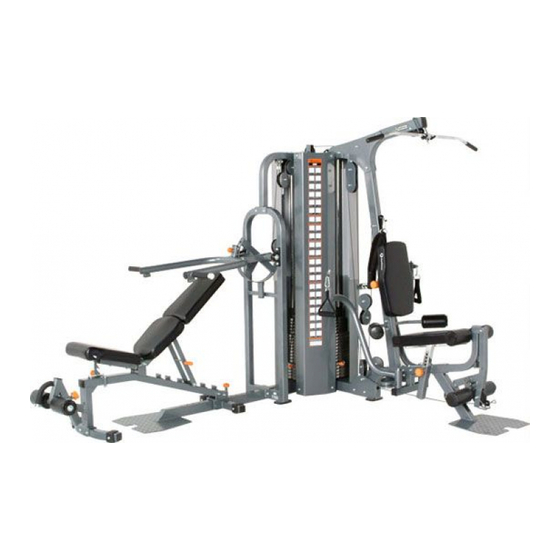
- Page 1 KF-2060 Owner’s Manual 215-00132 11/06 Rev A...
-
Page 2: Table Of Contents
Table of Contents Before You Start Important Safety Information Assembly Weight Ratios Weight Stack Sticker Placement Cable View Top View Exploded View Parts List Warranty Information 5-40... -
Page 3: Before You Start
This manual will guide you through the assembly process. If at any time you are having trouble with the assembly or use of this product, then please contact us at our Keys Fitness Helpline. We have trained service techni- cians on site to take care of you, our valued customer. -
Page 4: Important Safety Information
• This unit should only be used on a level surface and is intended for indoor use only. Keys Fitness recommends an equipment mat be placed under the unit to protect the floor or carpet and for easier cleaning. -
Page 5: Assembly
Assembly Box 1... - Page 6 Assembly Box 2...
- Page 7 Assembly Box 3...
- Page 8 Assembly Box 4...
- Page 9 Assembly Box 5...
- Page 10 Assembly Box 6...
- Page 11 Assembly Box 7 【52】5 Box 9 【53】9 Box 11 【54】5 Box 8 【52】5 Box 10 【53】9 Box 12 【54】5...
- Page 12 Assembly...
- Page 13 Assembly...
- Page 14 Assembly...
- Page 15 Assembly Step 1 Attach Right Base Frame (4) to Rear Frame (1) using two Nuts (144), four Washers (143), and two Bolts (137). Attach Left Base Frame (8) to Rear Frame (1) using two Nuts (144), four Washers (143), and two Bolts (137). Insert Guide Rods (47) into Rear Frame (1).
- Page 16 Assembly Step 2 Slide the weight plates down the Guide Rods (47) in this order - five 15lb Plates (52), nine 10lb Plates (53), five 5lb Plates (54), and the Top Plate (55). Note: Number of weight plates may vary depending on your specific configuration. Attach Top Frame (2) to all four Guide Rods (47) and secure to Rear Upright (3) using two Nuts (144), four Washers (143), and two Bolts (136).
- Page 17 Assembly Step 3 Attach Front Upright (19) to Seat Pad Support Receptacle (6) using two Nuts (144), four Washers (143), and two Bolts (136). Attach Seat Pad Support Receptacle (6) to Base Frame assembly using two Nuts (144), four Washers (143), and two Bolts (136). Figure 3...
- Page 18 Assembly Step 4 Attach Main Upright (7) to Seat Pad Support Receptacle using two Nuts (126), four Washers (125), and two Bolts (131). Attach Right Top Frame (5) to Top Frame assembly using two Nuts (144), four Washers (143), and two Bolts (137). Next, use two Washers (143), two Spring Washers (119), and two Bolts (142) to connect Right Top Frame (5) to Main Upright.
- Page 19 Assembly Step 5 Slide Press Station Base Frame (11) over Press Arm Support (10). Next, attach both pieces to Base Frame using two Nuts (144), four Washers (143), and two Bolts (134). Install Left Top Frame over Press Arm Support (10) and Top Frame assembly. Secure top section using two Nuts (144), four Washers (143), and two Bolts (137).
- Page 20 Assembly Step 6 Attach Pec Dec Mount (21) onto Seat Pad Support Receptacle using two Nuts (144), four Washers (143), and two Bolts (136). Secure in place with one Washer (129), one Spring Washer (119), and one Bolt (137). Figure 6...
- Page 21 Assembly Step 7 Attach Right and Left Leg Hold Leg Frames (29 & 30) using two Nuts (144), four Washers (143), and two Bolts (135). Figure 7...
- Page 22 Assembly Step 8 Slide the Right Pec Dec Arm (22) on to the shaft of the Pec Dec Mount. Secure the arm in place using one Big Washer (102), one Washer (143), one Spring Washer (119), and one Bolt (128). Slide Pec Dec Handle Bar (24) onto the top of the Right Pec Dec Arm (22) and secure using one Chrome Washer (101), one Washer (143), one Spring Washer (119), and one Bolt (128).
- Page 23 Assembly Step 9 Attach Leg Extension Lever (20) to Seat Pad Support Receptacle (6) and secure using Shaft (86), one Washer (117), one Spring Washer (118), and one Allen Bolt (98). Slide Foam Frame w/ Shaft (26) through the Leg Extension Lever (20) and attach Foam Frame w/o Shaft (25) to the other side.
- Page 24 Assembly Step 10 Align Press Arm (35) and Chest Press Cam (12) while inserting Press Station Shaft (38). Slide Pillow Block Bearing (75) onto each side of Press Station Shaft (38) and secure the assembly using two Chrome Washers (101), two Washers (143), two Spring Washers (119), and two Allen Bolts (128).
- Page 25 Assembly Step 11 Attach Bench Rear Frame (15) onto Bench Main Frame (13) and secure using two Nuts (144), four Washers (143), and two Bolts (133). Attach Bench Front Stabilizer (14) on to Bench Main Frame (13) using two Nuts (144), four Washers (143), and two Bolts (136).
- Page 26 Assembly Step 12 Attach Bench Seat Pad Support (16) to Bench Main Frame using one Nut (126), two Washer (125), and one Bolt (132). Insert Bench Seat Pad Adjustment Bar (64) into Bench Main Frame and secure using one Washer (125) and one Nut (126). Attach Spring (66) to Bench Main Frame and Bench Seat Pad Adjustment Bar (64).
- Page 27 Assembly Step 13 Attach Bench Back Pad Support (17) to Bench Main Frame using one Nut (126), two Washers (125), and one Bolt (132). Attach Bench Back Pad Adjustment Frame (39) to Bench Back Pad Support (17) using one Nut (126), two Washers (125), and one Bolt (132). Figure 13...
- Page 28 Assembly Step 14 Attach Bench Seat Pad (48), Bench Lower Back Pad (156) and Bench Back Pad (49) using six Washers (143) and six Bolts (138). Insert Foam Shaft (40) into Foam Adjustable Bracket (18). Next, attach Upholstered Roller Pads (58) using the following hardware: four Plastic Washers (90), two Chrome Washers (101), two Washers (143), two Spring Washers (119), and two Bolts (128).
- Page 29 Assembly Step 15 Attach Left and Right Squat Arms (36 & 37) to the Press Arm Assembly (35) using two Safety Pins (73). Next, slide Upholstered Roller Pad (58) onto each Squat Arm (36 & 37) and secure using two Plastic Washers (90), two Chrome Washers (101), two Washers (143), two Spring Washers (119), and two Bolts (128).
- Page 30 Assembly Step 16 Attach Back Pad (51) to Back Pad Adjustment Bracket (28) using two Washers (143) and two Bolts (127). Attach Seat Pad (50) to Seat Pad Support (27) using two Washers (143) and two Allen Bolts (127). Slide both assemblies into receptacles as shown in Figure 16. Figure 16...
- Page 31 Assembly Step 17 Slide two Upholstered Roller Pads (58) onto Foam Frames and secure using two Big Plugs (89). Slide the Long Foam Tube (34) through the hole in Seat Pad Support. Next, slide two Plastic Washers (90), two Upholstered Roller Pads (58), and two Big Plugs (89) onto each end of Long Foam Tube (34).
- Page 32 Assembly Step 18 Note: Stretch all cables out completely and make sure all twisting is removed before installing. Install Lat Cable (110) as detailed in Figure 18. Follow dotted lines to identify exact location of pulleys. See Page 43 “Cable View” for more detail. Start by threading cable end into Top Plate (55).
- Page 33 Assembly Step 19 Note: This step is only used if you do not have the Leg Press 3 attachment. If you do have Leg Press 3 attachment, please follow instructions located in that manual. Use the Cable Adapter (124) in place of the pulley. Note: Stretch all cables out completely and make sure all twisting is removed before installing.
- Page 34 Assembly Step 20 Note: Stretch all cables out completely and make sure all twisting is removed before installing. Install Low Row Cable (111) as detailed in Figure 20. Follow dotted lines to identify exact location of pulleys. See Page 43 “Cable View” for more detail. Start by installing cable under the pulley at Leg Extension location.
- Page 35 Assembly Step 21 Note: Stretch all cables out completely and make sure all twisting is removed before install- ing. Install Pec Dec Cable (112) as detailed in Figure 21. Follow dotted lines to identify exact location of pulleys. See Page 43 “Cable View” for more detail. You will need the following for installation: Cable (112) - Qty.
- Page 36 Assembly Step 22 Note: Stretch all cables out completely and make sure all twisting is removed before installing. Install Long Chest Cable (114) as detailed in Figure 22. Follow dotted lines to identify exact location of pulleys. See Page 43 “Cable View” for more detail. Start by installing cable into the “Press Station”...
- Page 37 Assembly Step 23 Note: Stretch all cables out completely and make sure all twisting is removed before installing. Install Short Chest Cable (115) as detailed in Figure 23. Follow dotted lines to identify exact location of pulleys. See Page 43 “Cable View” for more detail. Start by threading the cable into the floating pulley bracket.
- Page 38 Assembly Step 24 Connect Long Lat Bar (43) to the Lat Cable (110) using two Gear Hooks (87) and Short Chain (88). Connect Ab Strap (60) or Lat Strap (61) to Low Row Cable (111) using one Gear Hook (87). Connect Short Lat Bar (44) or Ankle Strap (62) to Low Row Cable (111) using two Gear Hooks (87) and Long Chain (116).
- Page 39 Assembly Step 25 Install Weight Shrouds (41) to the left and right side of the weight stacks using four Washers (117) and four Bolts (98). Install Weight Shroud (42) to the center of both weight stacks and secure using four Washers (117) and four Bolts (98).
-
Page 40: Assembly
Assembly Congratulations! You have completed the assembly of your new KF-2050. -
Page 41: Weight Ratios
Weight Ratios... -
Page 42: Weight Stack Sticker Placement
Weight Stack Sticker Placement Your new POWER SYSTEM unit can be purchased with either a 200 LB or 250 LB weight stack. Depending on which weight stack you have purchased will deter- mine which weight stack sticker numbers will be used. The weight stack images below show which weight stack sticker numbers are to be used on your weight stack. -
Page 43: Cable View
Cable View... -
Page 44: Top View
Top View... -
Page 45: Exploded View
Exploded View... -
Page 46: Parts List
Parts List Ref # Part # 223-01077 FRAME, REAR KF-2060 223-01078 FRAME, UP KF-2060 223-01079 UPRIGHT, REAR KF-2060 223-01080 FRAME, RIGHT BASE KF-2060 223-01081 FRAME, RIGHT TOP FOR GUIDE RODKF-2060 223-01093 RECEPTACLE, SEAT PAD SUPPORT KF-2060 223-01084 UPRIGHT, MAIN KF-2060 223-01085 FRAME, LEFT BASE KF-2060 223-01095... -
Page 47: Warranty Information
Product from you. This Warranty becomes VALID ONLY if the product is pur- chased through a Keys Fitness authorized dealer unless otherwise authorized by Keys Fitness in writing and must be assembled / installed according to the instructions included with the Product. - Page 48 Keys Fitness Products, L.P. 4009 Distribution Drive, Suite 250 Garland, Texas 75041 Customer Service: 1-888-380-0482...
Need help?
Do you have a question about the Power System KF-2060 and is the answer not in the manual?
Questions and answers