
Related Manuals for Keys Fitness Power System KPS-1500


Summary of Contents for Keys Fitness Power System KPS-1500
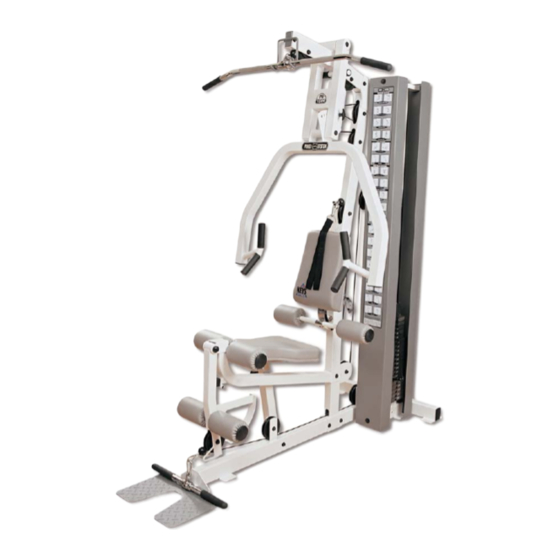
- Page 1 KPS-1500 1500 Questions? Call our toll free Keys Fitness Helpline 1 - 8 0 0 - 6 8 3 - 1 2 3 6...
- Page 2 This manual will guide you through the assembly process. If at any time you are having trouble with the assembly or use of this product, then please contact us at our Keys Fitness Helpline. We have trained service technicians on site to take care of you, our valued customer.
-
Page 3: Before You Start
• This Power System unit should only be used on a level surface and is intended for indoor use only. Keys Fitness recommends an equipment mat be placed under the unit to protect the floor or carpet and for easier cleaning. - Page 4 NOTE: Hand tighten bolts and nylon nuts until machine is fully assembled. STEP 1 Connect Base Frame (3) to Rear Upright (7) and Main Upright (4) using: 4 x (78) Bolt 4 x (82) Nylon Nut Slide Main Top Frame down onto Rear Upright (7) and Main Upright (4) using: 2 x (77) Bolt 2 x (78) Bolt...
- Page 5 NOTE: Hand tighten bolts and nylon nuts until machine is fully assembled. STEP 2 Attach Base Frame for Weight (9) to Base Frame (3) using: 1 x (41) Square Plate 4 x (73) Washer Screw Bolt (91) and Washer (92) into rear of Base Frame for Weight (9). Slide Guide Rods (14) down into Base Frame for Weight (4) and slide on the following: 2 x (40) Weight Stack Bumper...
- Page 6 NOTE: Hand tighten bolts and nylon nuts until machine is fully assembled. STEP 3 Secure Press Arm Suport (2) to Main Top Frame (5) using: 1 x (39) Press Arm Shaft Secure Press Arm (1) to Press Arm Support (2) using: 1 x (38) Press Arm Shaft 2 x (84) Screw Connect Lat Bar Hook (15) to Main Top Frame (5) using:...
- Page 7 NOTE: Hand tighten bolts and nylon nuts until machine is fully assembled. STEP 4 Complete Back Pad (55) assembly using: 1 x (6) Back Pad Support 1 x (81) Bolt 1 x (50) Nylon Nut 1 x (61) Long Foam Tube 2 x (63) Upholstered Roller Complete Seat Pad (54) and Frame connection using: 1 x (10) Seat Pad Receptacle...
- Page 8 NOTE: Hand tighten bolts and nylon nuts until machine is fully assembled. STEP 4 (Continued) Complete Leg Ext/Curl (12) to Seat Pad Receptacle (10) using: 2 x (51) Semi-Ball End Cap 1 x (46) Leg Extension Shaft 2 x (60) Foam Tube 4 x (63) Upholstered Roller 1 x (85) Screw Connect Foot Plate (13) to Base Frame (3) using:...
- Page 9 NOTE: Hand tighten bolts and nylon nuts until machine is fully assembled. STEP 5 Complete Cable (30,28,29) assembly using the following: 16 x (57) Pulley 10 x (53) Short Pulley Spacer 2 x (58) Pulley Plate 36 x (73) Washer 5 x (75) Bolt 5 x (95) Bolt ASSEMBLY...
- Page 10 TIGHTEN ALL BOLTS AND NUTS BEFORE PROCEEDING. STEP 6 Slide Shroud w/Slot (33) down into bolt (View A) at rear of weight stack and secure to Top Guide Rod Frame (8) using: 1 x (91) Bolt Secure Shroud (32) to Top Guide Rod Frame (8) and Base Frame for Weight (9) using: 2 x (91) Bolt STEP 6 CONTINUED ON PAGE 9...
- Page 11 STEP 6 Continued Connect attachments as pictured above for various exercises using: 3 x (69) Gear Clip 1 x (89) Chain 1 x (25) Abdominal Strap 1 x (26) Ankle Strap ASSEMBLY 1 x (24) Chain 1 x (70) Long Lat Bar 1 x (27) Single Handle Strap 1 x (71) Short Bar...
-
Page 12: Parts List
Description Press Arm Press Arm Support Base Frame Main Upright Main Top Frame Back Pad Support Rear Upright Top Guide Rod Frame Base Frame for Weight Seat Pad Support Receptacle Seat Pad Support Leg Extension/Curl Foot Plate Guide Rod Lat Bar Hook 10lb Plate 15lb Plate 5lb Plate... - Page 13 Description Washer 8 Selector Rod Screw Bolt M12x35 Bolt M10x50 PARTS LIST...
- Page 14 EXPLODED VIEW...
- Page 15 Product. To obtain warranty service, you must contact a Keys authorized retailer, service technician or Keys Fitness at our phone number located in this manual. Any parts determined to be defective must be returned to Keys to obtain warranty service. You must prepay any shipping charges, export taxes, custom duties and taxes, or any other charges associated with transportation of the parts or Product.
- Page 16 Keys Fitness Products, L.P. 4009 Distribution Drive, Suite 250 Garland, Texas 75041 Customer Service: 1-800-683-1236...
Need help?
Do you have a question about the Power System KPS-1500 and is the answer not in the manual?
Questions and answers