Advertisement
INSTALLATION INSTRUCTIONS AND INSTRUCTIONS FOR USE
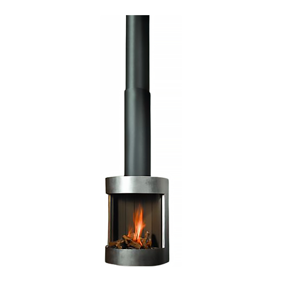
Wall-mounted gas fi re with closed combustion system
FREE BELL
Bellfi res wishes you many cosy evenings with your new Bellfi res gas fi re
This document is an essential part of your gas fi re.
Read it carefully before installation and use of the
gas fi re and keep it in a safe place!
Advertisement
Table of Contents

Related Manuals for Bellfires Free Bell


Summary of Contents for Bellfires Free Bell
- Page 1 INSTALLATION INSTRUCTIONS AND INSTRUCTIONS FOR USE Wall-mounted gas fi re with closed combustion system FREE BELL Bellfi res wishes you many cosy evenings with your new Bellfi res gas fi re This document is an essential part of your gas fi re.
- Page 3 Bellfi res English BELLFIRES WALL-MOUNTED GAS FIRE WITH CLOSED COMBUSTION SYSTEM: FREE BELL Instructions for use and installation instructions...
- Page 4 Bellfi res English Instructions for use and installation instructions...
-
Page 5: Table Of Contents
Bellfi res English CONTENTS Page 1. WARRANTY TERMS ................. 2. INSTRUCTIONS FOR USE ............... 3. INSTALLATION INSTRUCTIONS .............. 4. MAINTENANCE ..................5. FAULTS ...................... 6. ACCESSORIES ..................7. ELECTRICAL DIAGRAM ................8. DIMENSIONS .................... 9. TECHNICAL DETAILS/REGULATIONS ............ 10. REPLACEMENT PARTS LIST ..............11. - Page 6 Bellfi res English Instructions for use and installation instructions...
-
Page 7: Warranty Terms
Bellfi res English WARRANTY TERMS Bellfi res gas fi re Warranty Bellfi res guarantees the quality of the supplied hearth and the quality of the materials used. This warranty runs for a period of twelve (12) months from fi rst use of the hearth and covers defects which are a result of construction faults or the failure of component parts. - Page 8 Bellfi res English Instructions for use and installation instructions...
-
Page 9: Instructions For Use
Bellfi res English INSTRUCTIONS FOR USE INTRODUCTION Congratulations on your purchase of this modern Bellfi res wall-mounted gas fi re. This quality product will provide you with many years of enjoyment due to the fl ame effect and warmth that it provides. Please read the instructions for use carefully before using the appliance for the fi... - Page 10 Bellfi res English Ensure at all times that children and other people who are not aware of the operation of the gas appliance are only in the vicinity of the appliance exclusively under supervision. Use a fi reguard to protect the people and children mentioned above against possible burns.
- Page 11 Bellfi res English Figure 1: Hand-held transmitter Set the display • Connect the batteries. By simultaneously pressing OFF and (small fl ame), can be switched from °F (and 12 hour clock) to °C (and 24 hour clock), or vice versa. •...
- Page 12 Bellfi res English Figure 2: Receiver “RESET” button Operating possibilities It is possible to use the remote control in 3 ways to operate the appliance: You can cycle through the menu with operating possibilities by repeatedly depressing the SET button. the selected starting time (P1 or P2 ) or stopping time (P1 or P2 ) is...
- Page 13 Bellfi res English • The appliance will automatically revert to stand-by if: ° the hand-held transmitter is outside the range of the receiver for more than 6 hours. ° the batteries in the hand-held transmitter are almost depleted. ° the batteries in the receiver are fully depleted. •...
- Page 14 Bellfi res English Setting the desired temperature by pressing the SET button • Select the desired mode of operation briefl y. • Hold the SET button until the display fl ashes. • Set the temperature with (large fl ame) or (small fl...
- Page 15 Bellfi res English Connection Piezo Igniter (only for MANual control) ON/OFF Switch Operating Knob 8-wire Receiver Jack Motor-Knob Microswitch (in maximum position) Figure 3: Gas regulating block; Operating Knob in ON-position • Possible error messages: * 3x short audio signal, audible when the motor-knob operates: Receiver batteries need changing soon (having heard this signal, the appliance can be ignited another ten times approximately).
- Page 16 Bellfi res English Important: • If you turn on the main burner by pressing the (large fl ame) button, it must ignite within 10 seconds. If this does not happen, immediately close the gas tap and warn the fi tter. •...
- Page 17 Bellfi res English 2 Receiver: * Carefully pull the receiver assembly out of the compartment. * Open the cover. * Remove the batteries from the battery compartment. * Place four new 1.5V batteries (LR6 or AA type) as indicated in the battery compartment.
- Page 18 Bellfi res English Igniting the fi re • Open the gas supply valve in the gas pipe to the fi re. • Switch the “O I” switch on the gas regulating block to the “I” position. • Turn the motor-knob on the gas regulating block as far as it will go in a clockwise direction.
- Page 19 Bellfi res English 2.4 USING THE APPLIANCE FOR THE FIRST TIME The gas fi re is coated with a lacquer layer resistant to high temperature. During the fi rst hours of operation, the burning in of the lacquer may result in an unpleasant smell. This is harmless, however.
-
Page 20: Installation Instructions
Bellfi res English INSTALLATION INSTRUCTIONS 3.1 GENERAL The gas fi re must be positioned and connected as a “room sealed system” (balance fl ue) appliance by a CORGI registered gas installation engineer in accordance with the following installation instructions, nationally and locally applicable regulations (see “Technical Details/ Regulations”... - Page 21 Bellfi res English 3.3 PREPARATION FOR INSTALLATION The following preparation must be carried out before the gas fi re can be installed. 3.3.1 Instructions for positioning the outlet 3.3.1.1 Positioning the outlet for correct operation: Roof-mounted outlet: >0.5 m Figure 5: Roof-mounted outlet This must be positioned at least 0.5 m from the roof edge;...
- Page 22 Bellfi res English 3.3.1.2. Positioning the outlet to avoid affecting the surrounding area All listed “distances” in this section are no more than guidelines. For the exact minimum “distances”, please consult your national and local directives. Distance” = minimum distance required for positioning of the outlet to avoid adverse effects with respect to: A.
- Page 23 Bellfi res English Wall-mounted outlet: To avoid adverse effects Distance: outlet - A, B or C At walls in buildings with staggered Not permitted if A, B, or C are located heights. above the outlet. On a wall - general. (*) Above the outlet: >2 m Below the outlet:...
- Page 24 Bellfi res English GENERAL SERVICES 3.4.1 The Fume Channel/Combustion Air Intake The combined fume channel and combustion air intake requires one of the following Barbas concentric fl ue system confi gurations. Important: Due to the high temperature of the outer walls (approx.
- Page 25 (min.-max.) (min.-max.) restriction plate 0.5 - 1.0 m 0 - 0.6 m Free Bell 1.0 - 3.0 m 0 - 2.0 m Figure 8: Horizontal wall termination ALL SIZES INCLUDE THE LENGTH OF THE ROOF OR WALL TERMINATION Instructions for use and installation instructions...
- Page 26 (min.-max.) restriction plate 2.0 - 8.0 m Width: B = 50 mm Free Bell 8.0 - 12.0 m Width: B = 65 mm Figure 9: Vertical roof-mounted outlet without bend ALL SIZES INCLUDE THE LENGTH OF THE ROOF OR WALL TERMINATION...
- Page 27 (*) Distance X (*) Distance Y Assemble (min.-max.) (min.-max.) (min.-max.) restriction plate Free Bell 1.0 - 10.0 m 0 - 3.0 m 1.0 - 10.0 m Width: B = 30 mm (*) : (Y ) : X > 2 : 1 (vertical to horizontal ratio (or 45°...
- Page 28 (min.-max.) restriction plate 2.0 - 8.0 m Width: B = 50 mm Free Bell 8.0 - 12.0 m Width: B = 65 mm Figure 11: Vertical chimney outlet using an existing lined chimney (Flexible Ø100 mm and/or rigid Ø100 mm / Ø150 mm)
- Page 29 (*) Distance X (*) Distance Y Assemble (min.-max.) (min.-max.) (min.-max.) restriction plate Free Bell 1.0 - 10.0 m 0 - 3.0 m 1.0 - 10.0 m Width: B = 30 mm (*) : (Y ) : X > 2 : 1 (Vertical to horizontal ratio (or 45°...
- Page 30 (min.-max.) restriction plate 2.0 - 8.0 m Width: B = 50 mm Free Bell 8.0 - 12.0 m Width: B = 65 mm Figure 13: Vertical chimney outlet using an existing unsound lined chimney or when no chimney liners are present (Flexible Ø100 mm / Ø150 mm)
- Page 31 (*) Distance X (*) Distance Y Assemble (min.-max.) (min.-max.) (min.-max.) restriction plate Free Bell 1.0 - 10.0 m 0 - 3.0 m 1.0 - 10.0 m Width: B = 30 mm (*) : (Y ) : X > 2 : 1 (Vertical to horizontal ratio (or 45°...
- Page 32 3.4.2 Item descriptions for fi gures 8 t/m 14. FIG. NO. DESCRIPTION Wall-mounted gas fi re; Free Bell Restriction plate (Various restriction plates are supplied with the appliance.) Chimney, min. Ø150 mm internal, totally gas tight Chimney or fi reproof sleeving. Min. Ø160 mm internal Ø100 mm internal fl...
- Page 33 Bellfi res English Color(*) Application FIG. ART. / ORDER DESCRIPTION RVS antr. RIGID FLEX 302189 Ceiling plate for transition Ø100 mm / Ø150 mm rigid - Ø100 mm (fl ex.). Stainless steel adapter piece (100) from fi re to fl exible, Ø100 302278 mm external (rigid) x Ø107 mm internal (fl...
- Page 34 Bellfi res English : Color: RVS: Stainless steel self-colour, polished antr.: Anthracite colour lacquer, matt (**) : Adjustable roof fl ashing for a slope > 45° can be supplied on request. When installing a balanced-fl ue “closed” gas fi re in an existing chimney, ensure stain- less steel fl...
- Page 35 Bellfi res English The appliance comprises the following parts: Floor cove (optional) Ornamental hood (3 parts) Fireplace Frame 3.5.1 Suspending the fi re place Remove the frame by pulling the bottom edge free and lifting slightly upwards. Carefully remove the glass by fi rst unscrewing the glass strips left, right and on the bottom a little, and then removing the glass strip fully along the top edge.
- Page 36 Bellfi res English Ø154 (Ext.) Ø108 (Ext.) Ø150 (Int.) Ø100,8 (Int.) 125,5 Floor Gas connection * = position of fi xing holes 3.5.2 Connecting the concentric fl ue Assemble the concentric fl ue system according to one of the examples in section 3.4.1, fi...
- Page 37 Bellfi res English Maximum Rate Pilot Gas Adjustment Adjustment Screw (with Screwdriver) Motor-Knob Operating-Knob (Tab 2.8 x 0.8 mm) Connection piezo cable (Hand Control) Side-inlet Thermo Unit Connection Side-outlet Minimum Rate Adjustment Screw Inlet Pressure Tap Bottom Outlet Bottom Inlet Outlet Pressure Tap Figure 15: Gas regulating block Remote control Operating-Knob...
- Page 38 Bellfi res English 3.5.4 Positioning the ceramic log set, marble pebbles and ceramic stones The appliance can be supplied with: • Ceramic log set + embers • Ceramic stones • Marble pebbles Important: • Carefully place the embers, set of logs, the ceramic stones or the marble pebbles on and around the main burner according to the directions in this chapter.
- Page 39 Please make sure that all burner orifi ces (small holes) are kept unblocked! Embers and logs must not be placed next to the pilot light burner Keep the burner orifi ces unblocked Figure 17: Log set Free Bell (Natural gas and propane) Instructions for use and installation instructions...
- Page 40 Make sure that the pilot light remains free at all times. See fi gure 18. Do not block the pilot light Figure 18: Positioning stones Free Bell (Natural gas and propane) Instructions for use and installation instructions...
- Page 41 Bellfi res English 3.5.4.3 Marble pebbles 1 Place the ceramic mat on the burner in such a way that the holes in the mat are in line with the burner openings. 2 Spread the pebbles over the whole burner bed (burner and grid around the burner). Make sure that the pilot light remains free.
- Page 42 Bellfi res English Important: • Do not place any marble pebbles in front of the pilot light. Make sure that the pilot light can burn freely over the main burner. • Keep the burner orifi ces unblocked Only this way a proper ignition of the main burner is ensured. 3.5.5 Mounting fl...
- Page 43 Bellfi res English The following restriction plates are supplied: Restriction plate: Width: B = 30 mm Width: B = 50 mm Width: B = 65 mm 3.5.6 Fitting the glass Once the logs / stones / marble pebbles have been placed and, if necessary, the restriction plate has been installed, the glass can be replaced.
- Page 44 Bellfi res English 1 Place the rose around the concentric fl ue and screw this to the ceiling. 2 Push the top end of the upper ornamental pipe into the rose and screw the bottom end securely to the wall. 3 Hook the bottom end of the lower ornamental pipe behind the top plate of the appliance.
-
Page 45: Maintenance
Bellfi res English MAINTENANCE 4.1 ANNUAL MAINTENANCE It is essential that the appliance, the complete concentric fl ue system and the outlet are cleaned and inspected annually by a recognised fi tter/gas specialist. The safe operation of the appliance will thus remain guaranteed. Maintenance consists of the following: •... -
Page 46: Faults
Bellfi res English FAULTS Possible reasons for the gas fi re going out are: • The concentric fl ue system is not installed according to one of the methods detailed in Paragraph 3.4 • An incorrect “fl ue gas restriction plate” is fi tted. •... -
Page 47: Accessories
Bellfi res English ACCESSORIES • Floor cove: article no.: 323062 (anthracite). Viewing window R99.5 Floor cove 24.5 Ø12 16.25 Instructions for use and installation instructions... -
Page 48: Electrical Diagram
Bellfi res English ELECTRICAL DIAGRAM Operating-Knob Motor- knob Gas regulating block “black” Thermo - “O I” Switch current “red” Interrupter Block 8 Wire Connecting Cable cable 2 cable 1 Thermo- Antenna Ignition cable couple “yellow” “red” RECEIVER SPARK SPARK ON/OFF Switch Thermocurrent interrupter Block Pilot... -
Page 49: Dimensions
Bellfi res English DIMENSIONS 8.1 FREE BELL 125.5 Floor Instructions for use and installation instructions... - Page 50 Bellfi res English Instructions for use and installation instructions...
-
Page 51: Technical Details/Regulations
National installation regulations: Gas safety installation and use regulations 1984 plus all relevant safety and building regulations concerning fi re installation Model : FREE BELL Country : GB; Great Britain/IE; Ireland : GB; Great Britain/IE; Ireland Product identifi cation no... -
Page 52: Replacement Parts List
302062 Nut piezo electrode 310905 Pilot light olive; Ø4 mm 301976 Pilot light nut; Ø4 mm .... Pilot light pipe; Ø4 mm, L=….mm .... Burner pipe; Ø8 mm, L= …mm 322559 Glass Free Bell Instructions for use and installation instructions... - Page 53 Bellfi res English Logs - Embers - Stones - Marble pebbles Instructions for use and installation instructions...
-
Page 54: Disposal Of Packaging And Appliance
Bellfi res English DISPOSING OF PACKAGING AND APPLIANCE The appliance comes in recyclable packaging. This can include: • Cardboard • Wood • Plastic • Paper Such materials must be disposed of responsibly, in line with local regulations. Batteries should be disposed of as chemical waste. Batteries must be disposed of responsibly, in line with local regulations. - Page 55 Bellfi res English Instructions for use and installation instructions...
- Page 56 INTERFOCOS B.V. HALLENSTRAAT 17 5531 AB BLADEL NEDERLAND E-mail: info@interfocos.nl Internet: www.interfocos.com 03 - 151110 - 323010...
Need help?
Do you have a question about the Free Bell and is the answer not in the manual?
Questions and answers