Table of Contents
Advertisement
Quick Links
Download this manual
See also:
User Manual
Advertisement
Chapters
Table of Contents

Related Manuals for IEI Technology WAFER-945GSE


Summary of Contents for IEI Technology WAFER-945GSE
-
Page 1: User Manual
WAFER-945GSE 3.5" Motherboard IEI Technology Corp. MODEL: WAFER-945GSE 3.5" SBC with Intel® Atom™ Processor with support for VGA and LVDS Displays, Dual PCIe GbE, CF Type II, and SATA User Manual Page i Rev. 2.01 – 20 April, 2012... - Page 2 WAFER-945GSE 3.5" Motherboard Revision Date Version Changes 2.01 Updated Section 1.4: Dimensions 20 April, 2012 2.00 Updated for R20 version 20 September, 2011 1.04 23 August, 2011 Modified SATA connector description 1.03 15 June, 2009 Modified LVDS connector description in Section 3.2.10 1.02...
- Page 3 WAFER-945GSE 3.5" Motherboard Copyright COPYRIGHT NOTICE The information in this document is subject to change without prior notice in order to improve reliability, design and function and does not represent a commitment on the part of the manufacturer. In no event will the manufacturer be liable for direct, indirect, special, incidental, or consequential damages arising out of the use or inability to use the product or documentation, even if advised of the possibility of such damages.
-
Page 4: Table Of Contents
PTIONAL TEMS 3 CONNECTORS ......................13 3.1 P ..............14 ERIPHERAL NTERFACE ONNECTORS 3.1.1 WAFER-945GSE Layout .................. 14 3.1.2 Peripheral Interface Connectors ..............14 3.1.3 External Interface Panel Connectors............... 15 3.2 I ..............16 NTERNAL ERIPHERAL ONNECTORS 3.2.1 ATX Power Connector ..................16 3.2.2 ATX Power Supply Enable Connector ............. - Page 5 WAFER-945GSE 3.5" Motherboard 3.2.12 Power Button Connector................27 3.2.13 Reset Button Connector ................. 28 3.2.14 SATA Drive Connectors ................. 29 3.2.15 Serial Port Connectors, RS-232..............30 3.2.16 Serial Port Connector, RS-232/422/485 ............31 3.2.17 SPI Flash Connector..................32 3.2.18 USB Connectors (Internal) ................33 3.3 E...
- Page 6 WAFER-945GSE 3.5" Motherboard 4.6.6 Audio Kit Installation..................57 4.6.7 USB Cable (Dual Port without Bracket) (Optional)........58 4.7 E ........... 59 XTERNAL ERIPHERAL NTERFACE ONNECTION 4.7.1 LAN Connection....................60 4.7.2 Serial Device Connection ................60 4.7.3 USB Connection (Dual Connector) ..............61 4.7.4 VGA Monitor Connection ................
- Page 7 WAFER-945GSE 3.5" Motherboard 5.7.2 South Bridge Chipset Configuration.............. 102 5.8 E ........................103 6 SOFTWARE DRIVERS .................... 105 6.1 A ................106 VAILABLE OFTWARE RIVERS 6.2 S ................106 TARTING THE RIVER ROGRAM 6.3 C ................108 HIPSET RIVER NSTALLATION 6.4 VGA D...
- Page 8 WAFER-945GSE 3.5" Motherboard D.2 DIO C ................... 159 ONNECTOR INOUTS D.3 A ................159 SSEMBLY ANGUAGE AMPLES D.3.1 Enable the DIO Input Function ..............159 D.3.2 Enable the DIO Output Function..............160 E WATCHDOG TIMER....................161 F HAZARDOUS MATERIALS DISCLOSURE............164 F.1 H...
- Page 9 WAFER-945GSE 3.5" Motherboard List of Figures Figure 1-1: WAFER-945GSE ......................2 Figure 1-2: Connectors ........................3 Figure 1-3: WAFER-945GSE Dimensions (mm)................5 Figure 1-4: Data Flow Diagram......................6 Figure 3-1: Connectors and Jumpers..................14 Figure 3-2: ATX Power Connector Location ................16 Figure 3-3: ATX Power Supply Enable Connector Location ............17 Figure 3-4: Audio Connector Pinouts (10-pin)................18...
- Page 10 WAFER-945GSE 3.5" Motherboard Figure 4-4: CF Card Setup Jumper Location ................45 Figure 4-5: Clear BIOS Jumper Location ...................46 Figure 4-6: COM 2 Function Select Jumper Location...............47 Figure 4-7: LVDS Panel Resolution Jumper Pinout Locations..........48 Figure 4-8: LVDS Voltage Selection Jumper Pinout Locations ..........49 Figure 4-9: SATA Drive Cable Connection.................51...
- Page 11 WAFER-945GSE 3.5" Motherboard Figure 6-17: LAN Driver Welcome Screen ................118 Figure 6-18: LAN Driver Welcome Screen ................118 Figure 6-19: LAN Driver Installation ..................119 Figure 6-20: LAN Driver Installation Complete............... 119 Figure 6-21: Audio Driver Installation File Extraction............120 Figure 6-22: Audio Driver Installation Welcome Screen............
- Page 12 WAFER-945GSE 3.5" Motherboard Figure B-28: Recovery Complete Window ................147 Figure B-29: Backup System....................148 Figure B-30: System Backup Complete Window ..............148 Figure B-31: Restore Backup ....................149 Figure B-32: Restore System Backup Complete Window ............. 149 Figure B-33: Symantec Ghost Window ................... 150...
- Page 13 WAFER-945GSE 3.5" Motherboard List of Tables Table 1-1: WAFER-945GSE Model Variations................2 Table 1-2: WAFER-945GSE Specifications ..................8 Table 2-1: Packing List.........................12 Table 2-2: Optional Items......................12 Table 3-1: Peripheral Interface Connectors ................15 Table 3-2: Rear Panel Connectors ....................15 Table 3-3: ATX Power Connector Pinouts .................16 Table 3-4: ATX Power Supply Enable Connector Pinouts ............17...
- Page 14 WAFER-945GSE 3.5" Motherboard Table 4-2: AT Power Select Jumper Settings ................44 Table 4-3: CF Card Setup Jumper Settings ................45 Table 4-4: Clear BIOS Jumper Settings..................46 Table 4-5: COM 2 Function Select Jumper Settings ..............46 Table 4-6: LVDS Panel Resolution Jumper Settings..............47 Table 4-7: LVDS Voltage Selection Jumper Settings..............48...
- Page 15 WAFER-945GSE 3.5" Motherboard BIOS Menus BIOS Menu 1: Main ........................68 BIOS Menu 2: Advanced ......................69 BIOS Menu 3: CPU Configuration ....................70 BIOS Menu 4: IDE Configuration....................71 BIOS Menu 5: IDE Master and IDE Slave Configuration ............72 BIOS Menu 6: Super IO Configuration..................77 BIOS Menu 7: Hardware Health Configuration ................80...
-
Page 16: Introduction
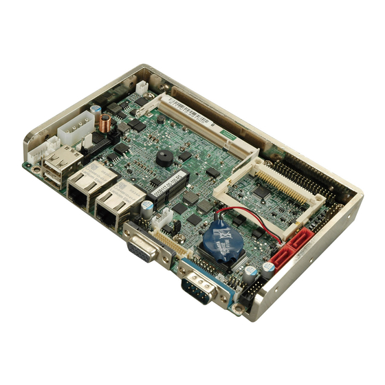
WAFER-945GSE 3.5" Motherboard Chapter Introduction Page 1... -
Page 17: Introduction
The Intel® Atom™ processor N270 embedded on the WAFER-945GSE has a 1.60 GHz clock speed, a 533 MHz FSB and a 512 KB L2 cache. The WAFER-945GSE also supports one 200-pin 533 MHz 2.0 GB (max.) DDR2 SDRAM SO-DIMM. The board comes with an LVDS connector and supports both 18-bit and 36-bit single channel LVDS screens. -
Page 18: Connectors
WAFER-945GSE 3.5" Motherboard 1.3 Connectors The connectors on the WAFER-945GSE are shown in the figure below. Figure 1-2: Connectors The WAFER-945GSE has the following connectors on-board: 1 x ATX power connector 1 x ATX enable connector 1 x Audio connector 1 x Backlight inverter connector 1 x CompactFlash®... - Page 19 2 x Serial ATA (SATA) drive connectors 1 x SPI flash connector 2 x USB 2.0 connectors (supports four USB 2.0 devices) The WAFER-945GSE has the following external peripheral interface connectors on the board rear panel. 2 x Ethernet connectors...
-
Page 20: Dimensions
WAFER-945GSE 3.5" Motherboard 1.4 Dimensions The main dimensions of the WAFER-945GSE are shown in the diagram below: Figure 1-3: WAFER-945GSE Dimensions (mm) Page 5... -
Page 21: Data Flow
WAFER-945GSE 3.5" Motherboard 1.5 Data Flow F igure 1-4 shows the data flow between the system chipset, the CPU and other components installed on the motherboard. Figure 1-4: Data Flow Diagram Page 6... -
Page 22: Technical Specifications
WAFER-945GSE 3.5" Motherboard 1.6 Technical Specifications WAFER-945GSE technical specifications are listed below. Specification/Model WAFER-945GSE 3.5” Form Factor 45 nm 1.6 GHz Intel® Atom™ N270 System CPU 533 MHz Front Side Bus (FSB) System Chipset Northbridge: Intel® 945GSE Southbridge: Intel® ICH7-M Memory One 200-pin SO-DIMM socket supports one 400 MHz or 533 MHz 2.0... -
Page 23: Table 1-2: Wafer-945Gse Specifications
(1.6 GHz Intel® Atom™ with one 1.0 GB DDR2 SO-DIMM) Temperature 0ºC ~ 60ºC Humidity (operating) 5% ~ 95% (non-condensing) Dimensions (LxW) 146 mm x 102 mm Weight (GW/NW) 700 g / 230 g Table 1-2: WAFER-945GSE Specifications Page 8... -
Page 24: Packing List
WAFER-945GSE 3.5" Motherboard Chapter Packing List Page 9... -
Page 25: Anti-Static Precautions
Only handle the edges of the PCB: Don't touch the surface of the motherboard. Hold the motherboard by the edges when handling. 2.2 Unpacking Precautions When the WAFER-945GSE is unpacked, please do the following: Follow the antistatic guidelines above. Make sure the packing box is facing upwards when opening. -
Page 26: Packing List
If any of the components listed in the checklist below are missing, do not proceed with the installation. Contact the IEI reseller or vendor the WAFER-945GSE was purchased from or contact an IEI sales representative directly by sending an email to ales@iei.com.tw. -
Page 27: Optional Items
WAFER-945GSE 3.5" Motherboard Quantity Item and Part Number Image Mini jumper pack (2.0mm) (P/N:33100-000033-RS) Utility CD Quick Installation Guide Table 2-1: Packing List 2.4 Optional Items The following are optional components which may be separately purchased: Item and Part Number... -
Page 28: Connectors
WAFER-945GSE 3.5" Motherboard Chapter Connectors Page 13... -
Page 29: Peripheral Interface Connectors
WAFER-945GSE 3.5" Motherboard 3.1 Peripheral Interface Connectors This chapter details all the jumpers and connectors. 3.1.1 WAFER-945GSE Layout The figures below show all the connectors and jumpers. Figure 3-1: Connectors and Jumpers 3.1.2 Peripheral Interface Connectors The table below lists all the connectors on the board. -
Page 30: External Interface Panel Connectors
WAFER-945GSE 3.5" Motherboard Connector Type Label Digital input/output (DIO) connector 10-pin header DIO1 Fan connector 3-pin wafer CPU_FAN1 Keyboard and mouse connector 6-pin wafer KB_MS1 LED connector 6-pin header LED_C1 LVDS connector 30-pin crimp LVDS1 PCIe Mini Card slot PCIe Mini Slot... -
Page 31: Internal Peripheral Connectors
WAFER-945GSE 3.5" Motherboard 3.2 Internal Peripheral Connectors The section describes all of the connectors on the WAFER-945GSE. 3.2.1 ATX Power Connector CN Label: ATXPWR1 4-pin ATX power connector CN Type: CN Location: See Figure 3-2 CN Pinouts: See Table 3-3 The ATX power connector connects to an ATX power supply. -
Page 32: Audio Connector (10-Pin)
The ATX power supply enable connector enables the WAFER-945GSE to be connected to an ATX power supply. In default mode, the WAFER-945GSE can only use an AT power supply. To enable an ATX power supply, the AT Power Select jumper must also be configured. -
Page 33: Backlight Inverter Connector
3.2.4 Backlight Inverter Connector CN Label: INVERTER1 5-pin wafer CN Type: CN Location: See Figure 3-5 CN Pinouts: See Table 3-6 The backlight inverter connectors provide the backlights on the LCD display connected to the WAFER-945GSE with +12V of power. Page 18... -
Page 34: Compactflash® Socket
WAFER-945GSE 3.5" Motherboard Figure 3-5: Panel Backlight Connector Location Description LCD Backlight Control +12V BACKLIGHT Enable Table 3-6: Panel Backlight Connector Pinouts 3.2.5 CompactFlash® Socket CN Label: CN Type: 50-pin header See Figure 3-6 CN Location: CN Pinouts: See Table 3-7 A CF Type I or Type II memory card can be inserted to the CF socket on the WAFER-945GSE. -
Page 35: Figure 3-6: Cf Card Socket Location
WAFER-945GSE 3.5" Motherboard Figure 3-6: CF Card Socket Location Description Description GROUND VCC-IN CHECK1 DATA 3 DATA 11 DATA 4 DATA 12 DATA 5 DATA 13 DATA 6 DATA 14 DATA 7 DATA 15 HDC_CS0# HDC_CS1 GROUND GROUND IOR# GROUND... -
Page 36: Digital Input/Output (Dio) Connector
WAFER-945GSE 3.5" Motherboard Description Description 66DET DATA 0 66DET DATA 1 DATA 8 DATA 2 DATA 9 DATA 10 VCC-IN CHECK2 GROUND Table 3-7: CF Card Socket Pinouts 3.2.6 Digital Input/Output (DIO) Connector CN Label: DIO1 10-pin header CN Type:... -
Page 37: Fan Connector (+12V, 3-Pin)
WAFER-945GSE 3.5" Motherboard 3.2.7 Fan Connector (+12V, 3-pin) CN Label: CPU_FAN1 3-pin wafer CN Type: CN Location: See Figure 3-8 CN Pinouts: See Table 3-9 The cooling fan connector provides a 12V, 500mA current to the cooling fan. The connector has a "rotation" pin to get rotation signals from fans and notify the system so the system BIOS can recognize the fan speed. -
Page 38: Led Connector
WAFER-945GSE 3.5" Motherboard The keyboard and mouse connector can be connected to a standard PS/2 cable or PS/2 Y-cable to add keyboard and mouse functionality to the system. Figure 3-9: Keyboard/Mouse Connector Location Description +5 V KB DATA MS DATA... -
Page 39: Lvds Lcd Connector
WAFER-945GSE 3.5" Motherboard Figure 3-10: LED Connector Location Description Power LED+ Power LED- HDD LED+ HDD LED- Table 3-11: LED Connector Pinouts 3.2.10 LVDS LCD Connector CN Label: LVDS1 CN Type: 30-pin crimp See Figure 3-11 CN Location: CN Pinouts:... -
Page 40: Figure 3-11: Lvds Lcd Connector Pinout Locations
WAFER-945GSE 3.5" Motherboard Figure 3-11: LVDS LCD Connector Pinout Locations Description Description GND1 GND2 A_Y0 A_Y0# A_Y1 A_Y1# A_Y2 A_Y2# A_CK A_CK# GND3 GND4 B_Y0 B_Y0# B_Y1 B_Y1# B_Y2 B_Y2# B_CK B_CK# GND5 GND6 VCC_LCD VCC_LCD VCC_LCD VCC_LCD Table 3-12: LVDS LCD Port Connector Pinouts... -
Page 41: Pcie Mini Card Slot
WAFER-945GSE 3.5" Motherboard 3.2.11 PCIe Mini Card Slot CN Label: 52-pin Mini PCIe Card Slot CN Type: CN Location: See Figure 3-12 CN Pinouts: See Table 3-13 The PCIe mini card slot enables a PCIe mini card expansion module to be connected to the board. -
Page 42: Power Button Connector
WAFER-945GSE 3.5" Motherboard Description Description VCC3 PCIRST# PERN2 3VDual PERP2 1.5V SMBCLK PETN2 SMBDATA PETP2 USBD- USBD+ RF_LINK# BLUELED# 1.5V VCC3 Table 3-13: PCIe Mini Card Slot Pinouts 3.2.12 Power Button Connector CN Label: PWRBTN1 CN Type: 2-pin wafer CN Location:... -
Page 43: Reset Button Connector
WAFER-945GSE 3.5" Motherboard Figure 3-13: Power Button Connector Location Description Power Switch Table 3-14: Power Button Connector Pinouts 3.2.13 Reset Button Connector CN Label: RESET1 CN Type: 2-pin wafer CN Location: See Figure 3-14 CN Pinouts: See Table 3-15 The reset button connector is connected to a reset switch on the system chassis to enable users to reboot the system when the system is turned on. -
Page 44: Sata Drive Connectors
WAFER-945GSE 3.5" Motherboard Description Reset Switch Table 3-15: Reset Button Connector Pinouts 3.2.14 SATA Drive Connectors CN Label: SATA1, SATA2 CN Type: 7-pin SATA drive connector CN Location: See Figure 3-15 CN Pinouts: See Table 3-16 The SATA drive connectors can be connected to SATA drives and support up to 3Gb/s data transfer rate. -
Page 45: Serial Port Connectors, Rs-232
WAFER-945GSE 3.5" Motherboard 3.2.15 Serial Port Connectors, RS-232 CN Label: COM3, COM4, COM5, COM6 40-pin header CN Type: CN Location: See Figure 3-16 CN Pinouts: See Table 3-17 The 40-pin serial port connector contains the following four serial ports: COM3, COM4, COM5 and COM6. -
Page 46: Serial Port Connector, Rs-232/422/485
WAFER-945GSE 3.5" Motherboard Description Description RECEIVE DATA (RXD4) REQUEST TO SEND (RTS4) TRANSMIT DATA (TXD4) CLEAR TO SEND (CTS4) DATA TERMINAL READY (DTR4) RING INDICATOR (RI4) DATA CARRIER DETECT (DCD5) DATA SET READY (DSR5) RECEIVE DATA (RXD5) REQUEST TO SEND (RTS5) -
Page 47: Spi Flash Connector
WAFER-945GSE 3.5" Motherboard Figure 3-17: RS-232/422/485 Serial Port Connector Location Description Description NDCD NDSR2 NRTS2 NCTS2 NDTR NRI2 TXD485+ TXD485 RXD485+ RXD485# Table 3-18: RS-232/422/485 Serial Port Connector Pinouts 3.2.17 SPI Flash Connector CN Label: JSPI1 CN Type: 8-pin header (2x4) -
Page 48: Usb Connectors (Internal)
WAFER-945GSE 3.5" Motherboard Figure 3-18: SPI Flash Connector Description Description CLOCK Table 3-19: SPI Flash Connector 3.2.18 USB Connectors (Internal) CN Label: USB01 and USB23 CN Type: 8-pin header CN Location: See Figure 3-19 CN Pinouts: See Table 3-20 The 2x4 USB pin connectors each provide connectivity to two USB 1.1 or two USB 2.0 ports. -
Page 49: External Peripheral Interface Connector Panel
WAFER-945GSE 3.5" Motherboard Figure 3-19: USB Connector Pinout Locations Description Description DATA- DATA+ DATA+ DATA- Table 3-20: USB Port Connector Pinouts 3.3 External Peripheral Interface Connector Panel The figure below shows the external peripheral interface connector (EPIC) panel. The EPIC panel consists of the following:... -
Page 50: Ethernet Connectors
CN Pinouts: See Table 3-21 The WAFER-945GSE is equipped with two built-in RJ-45 Ethernet controllers. The controllers can connect to the LAN through two RJ-45 LAN connectors. There are two LEDs on the connector indicating the status of LAN. The pin assignments are listed in the... -
Page 51: Serial Port Connectors (Com1)
3.3.3 USB Connectors CN Label: USB_C45 CN Type: Dual USB port CN Location: See Figure 3-20 CN Pinouts: See Table 3-24 The WAFER-945GSE has two external USB 2.0 ports. The ports connect to both USB 2.0 and USB 1.1 devices. Page 36... -
Page 52: Vga Connector
CN Label: VGA1 15-pin Female CN Type: CN Location: See Figure 3-20 CN Pinouts: See Figure 3-23 and Table 3-25 The WAFER-945GSE has a single 15-pin female connector for connectivity to standard display devices. DESCRIPTION DESCRIPTION GREEN BLUE CRT_PLUG- DDC DAT... -
Page 53: Installation
WAFER-945GSE 3.5" Motherboard Chapter Installation Page 38... -
Page 54: Anti-Static Precautions
WAFER-945GSE and severe injury to the user. Electrostatic discharge (ESD) can cause serious damage to electronic components, including the WAFER-945GSE. Dry climates are especially susceptible to ESD. It is therefore critical that whenever the WAFER-945GSE or any other electrical component is handled, the following anti-static precautions are strictly adhered to. - Page 55 Before and during the installation please DO the following: Read the user manual: The user manual provides a complete description of the WAFER-945GSE installation instructions and configuration options. Wear an electrostatic discharge cuff (ESD): Electronic components are easily damaged by ESD. Wearing an ESD cuff removes ESD from the body and helps prevent ESD damage.
-
Page 56: So-Dimm And Cf Card Installation
Figure 4-1. Figure 4-1: SO-DIMM Installation Step 1: Locate the SO-DIMM socket. Place the WAFER-945GSE on an anti-static pad. Step 2: Align the SO-DIMM with the socket. The SO-DIMM must be oriented in such a way that the notch in the middle of the SO-DIMM must be aligned with the plastic bridge in the socket. -
Page 57: Cf Card Installation
Secure the SO-DIMM. Release the arms on the SO-DIMM socket. They clip into place and secure the SO-DIMM in the socket. 4.3.2 CF Card Installation To install the CF card (Type 1 or Type 2) onto the WAFER-945GSE, please follow the steps below: Step 1: Locate the CF card socket. -
Page 58: Jumper Settings
WAFER-945GSE 3.5" Motherboard 4.4 Jumper Settings NOTE: A jumper is a metal bridge used to close an electrical circuit. It consists of two or three metal pins and a small metal clip (often protected by a plastic cover) that slides over the pins to connect them. To... -
Page 59: Cf Card Setup
WAFER-945GSE 3.5" Motherboard Jumper Label: ATXCTL1 Jumper Type: 3-pin header Jumper Settings: See Table 4-2 Jumper Location: See Figure 4-3 The AT Power Select jumper specifies the systems power mode as AT or ATX. Setting Description Short 2-3 Use AT power (Default) -
Page 60: Clear Cmos Jumper
Jumper Location: See Figure 4-5 If the WAFER-945GSE fails to boot due to improper BIOS settings, the clear CMOS jumper clears the CMOS data and resets the system BIOS information. To do this, use the jumper cap to close pins 2 and 3 for a few seconds then reinstall the jumper clip back to pins 1 and 2. -
Page 61: Com 2 Function Select Jumper
WAFER-945GSE 3.5" Motherboard Setting Description Short 1-2 Keep CMOS Setup (Default) Short 2-3 Clear CMOS Setup Table 4-4: Clear BIOS Jumper Settings Figure 4-5: Clear BIOS Jumper Location 4.4.4 COM 2 Function Select Jumper Jumper Label: 8-pin header Jumper Type:... -
Page 62: Lvds1 Panel Resolution Jumper
WAFER-945GSE 3.5" Motherboard Figure 4-6: COM 2 Function Select Jumper Location 4.4.5 LVDS1 Panel Resolution Jumper Jumper Label: J_LCD_TYPE1 8-pin header Jumper Type: Jumper Settings: See Table 4-6 Jumper Location: See Figure 4-7 The LVDS1 Panel Resolution jumper allows the resolution of the LVDS screens connected to the LVDS1 connector to be configured. -
Page 63: Lvds Voltage Selection
Figure 4-7: LVDS Panel Resolution Jumper Pinout Locations 4.4.6 LVDS Voltage Selection WARNING: Permanent damage to the screen and WAFER-945GSE may occur if the wrong voltage is selected with this jumper. Please refer to the user guide that came with the monitor to select the correct voltage. -
Page 64: Chassis Installation
The WAFER-945GSE must be installed in a chassis with ventilation holes on the sides allowing airflow to travel through the heat sink surface. In a system with an individual power supply unit, the cooling fan of a power supply can also help generate airflow through the board surface. -
Page 65: Motherboard Installation
This section outlines the installation of peripheral devices to the onboard connectors. 4.6.1 SATA Drive Connection The WAFER-945GSE is shipped with two SATA drive cables and one SATA drive power cable. To connect the SATA drives to the connectors, please follow the steps below. -
Page 66: Figure 4-9: Sata Drive Cable Connection
WAFER-945GSE 3.5" Motherboard Figure 4-9: SATA Drive Cable Connection Step 3: Connect the cable to the SATA disk. Connect the connector on the other end of the cable to the connector at the back of the SATA drive. See Figure 4-10. -
Page 67: Serial Port Connector Cable (Four Ports) Cable Connection
The SATA power cable can be bought from IEI. See Optional Items in Section 2.4. 4.6.2 Serial Port Connector Cable (Four Ports) Cable Connection The WAFER-945GSE is shipped with one four serial port connector cable. The four serial port connector cable connects four serial port connectors on the cable to the 40-pin serial port connector on the WAFER-945GSE. -
Page 68: Dual Rs-232 Cable Connection (W/O Bracket) (Optional)
WAFER-945GSE 3.5" Motherboard Figure 4-11: Four Serial Port Connector Cable Connection Step 4: Attach DB-9 serial port connectors to the chassis. The four DB-9 serial port connectors can be inserted into four preformed holes in the chassis. Once, inserted the DB-9 connectors should be secured to the chassis with the retention screws. -
Page 69: 4-Com Port Adapter Board Connection (Optional)
4.6.4 4-COM Port Adapter Board Connection (Optional) An optional, separately purchased 4-COM port adapter board may be shipped with the WAFER-945GSE. To install the 4-COM Port Adapter Board, please follow the steps below. Step 1: Locate the COM connector. The locations of the COM port connectors are shown in Chapter 3. -
Page 70: Figure 4-13: 4-Com Port Adapter Board
WAFER-945GSE 3.5" Motherboard properly aligned with the connector on the adapter board. Make sure the pin 1 on the adapter board connector and the cable connector are aligned. See Figure 4-13. Figure 4-13: 4-COM Port Adapter Board Step 4: Secure the adapter board to the chassis. Make sure the retention screws on either side of each COM port DB-9 connector are firmly secured to the chassis enclosure. -
Page 71: Keyboard/Mouse Y-Cable Connector
The WAFER-945GSE is shipped with a keyboard/mouse Y-cable connector. The keyboard/mouse Y-cable connector connects to a keyboard/mouse connector on the WAFER-945GSE and branches into two cables that are each connected to a PS/2 connector, one for a mouse and one for a keyboard. To connect the keyboard/mouse Y-cable connector, please follow the steps below. -
Page 72: Audio Kit Installation
The Audio Kit that came with the WAFER-945GSE connects to the 10-pin audio connector on the WAFER-945GSE. The audio kit consists of three audio jacks. One audio jack, Mic In, connects to a microphone. The remaining two audio jacks, Line-In and Line-Out, connect to two speakers. -
Page 73: Usb Cable (Dual Port Without Bracket) (Optional)
4.6.7 USB Cable (Dual Port without Bracket) (Optional) The WAFER-945GSE is shipped with a dual port USB 2.0 cable. To connect the USB cable connector, please follow the steps below. -
Page 74: External Peripheral Interface Connection
If the USB pins are not properly aligned, the USB device can burn out. Step 2: Align the connectors. The cable has two connectors. Correctly align pin 1on each cable connector with pin 1 on the WAFER-945GSE USB connector. Step 3: Insert the cable connectors. Once the cable connectors are properly aligned with the USB connectors on the WAFER-945GSE, connect the cable connectors to the on-board connectors. -
Page 75: Lan Connection
RJ-45 connector into the on-board RJ-45 connector. 4.7.2 Serial Device Connection The WAFER-945GSE has a single female DB-9 connector on the external peripheral interface panel for a serial device. Follow the steps below to connect a serial device to the WAFER-945GSE. -
Page 76: Usb Connection (Dual Connector)
WAFER-945GSE 3.5" Motherboard Step 1: Locate the DB-9 connector. The location of the DB-9 connector is shown in Chapter 3. Step 2: Insert the serial connector. Insert the DB-9 connector of a serial device into the DB-9 connector on the external peripheral interface. See Figure 4-19. -
Page 77: Vga Monitor Connection
Figure 4-20: USB Connector 4.7.4 VGA Monitor Connection The WAFER-945GSE has a single female DB-15 connector on the external peripheral interface panel. The DB-15 connector is connected to a CRT or VGA monitor. To connect a monitor to the WAFER-945GSE, please follow the instructions below. -
Page 78: Heat Sink Enclosure
4.8 Heat Sink Enclosure WARNING: Never run the WAFER-945GSE without the heat sink secured to the board. The heat sink ensures the system remains cool and does not need addition heat sinks to cool the system. -
Page 79: Figure 4-22: Heat Sink Retention Screws
When the WAFER-945GSE is shipped it is secured to a heat sink with five retention screws. If the WAFER-945GSE must be removed from the heat sink, the five retention screws must be removed. -
Page 80: Bios
WAFER-945GSE 3.5" Motherboard Chapter BIOS Page 65... -
Page 81: Introduction
WAFER-945GSE 3.5" Motherboard 5.1 Introduction The BIOS is programmed onto the BIOS chip. The BIOS setup program allows changes to certain system settings. This chapter outlines the options that can be changed. 5.1.1 Starting Setup The AMI BIOS is activated when the computer is turned on. The setup program can be activated in one of two ways. -
Page 82: Getting Help
WAFER-945GSE 3.5" Motherboard Function F2/F3 key Change color from total 3 colors. F2 to select color forward Save all the CMOS changes, only for Main Menu Table 5-1: BIOS Navigation Keys 5.1.3 Getting Help When F1 is pressed a small help window describing the appropriate keys to use and the possible selections for the highlighted item appears. -
Page 83: Main
WAFER-945GSE 3.5" Motherboard 5.2 Main The Main BIOS menu (BIOS Menu 1) appears when the BIOS Setup program is entered. The Main menu gives an overview of the basic system information. BIOS SETUP UTILITY Main Advanced PCIPnP Boot Security Chipset... -
Page 84: Advanced
WAFER-945GSE 3.5" Motherboard The System Overview field also has two user configurable fields: System Time [xx:xx:xx] Use the System Time option to set the system time. Manually enter the hours, minutes and seconds. System Date [xx/xx/xx] Use the System Date option to set the system date. Manually enter the day, month and year. -
Page 85: Cpu Configuration
WAFER-945GSE 3.5" Motherboard 5.3.1 CPU Configuration Use the CPU Configuration menu (BIOS Menu 3) to view detailed CPU specifications and configure the CPU. BIOS SETUP UTILITY Advanced Configure advanced CPU Settings Module Version:3F.10 ⎯⎯⎯⎯⎯⎯⎯⎯⎯⎯⎯⎯⎯⎯⎯⎯⎯⎯⎯⎯⎯⎯⎯⎯⎯⎯⎯⎯⎯⎯⎯ Manufacturer :Intel Genuine Intel(R) CPU N270 @ 1.60GHz Frequency :1.60GHz... -
Page 86: Bios Menu 4: Ide Configuration
WAFER-945GSE 3.5" Motherboard BIOS SETUP UTILITY Advanced IDE Configuration Options ⎯⎯⎯⎯⎯⎯⎯⎯⎯⎯⎯⎯⎯⎯⎯⎯⎯⎯⎯⎯⎯⎯⎯⎯⎯⎯⎯⎯⎯⎯⎯ Disabled ATA/IDE Configuration [Compatible] Compatible Legacy IDE Channels [SATA Pri, PATA Sec] Enhanced > Primary IDE Master : [Not Detected] > Primary IDE Slave : [Not Detected] Select Screen >... -
Page 87: Ide Master, Ide Slave
WAFER-945GSE 3.5" Motherboard PATA Only The IDE drives are enabled on the primary and secondary IDE channels. SATA drives are disabled. IDE Master and IDE Slave When entering setup, BIOS auto detects the presence of IDE devices. BIOS displays the status of the auto detected IDE devices. -
Page 88: Auto-Detected Drive Parameters
WAFER-945GSE 3.5" Motherboard Auto-Detected Drive Parameters The “grayed-out” items in the left frame are IDE disk drive parameters automatically detected from the firmware of the selected IDE disk drive. The drive parameters are listed as follows: Device: Lists the device type (e.g. hard disk, CD-ROM etc.) -
Page 89: Lba/Large Mode [Auto]
WAFER-945GSE 3.5" Motherboard drive is attached to the specified IDE channel. The BIOS does not attempt to search for other types of IDE disk drives on the specified channel. ARMD This option specifies an ATAPI Removable Media Device. These include, but are not limited to:... -
Page 90: Pio Mode [Auto]
WAFER-945GSE 3.5" Motherboard PIO Mode [Auto] Use the PIO Mode option to select the IDE PIO (Programmable I/O) mode program timing cycles between the IDE drive and the programmable IDE controller. As the PIO mode increases, the cycle time decreases. -
Page 91: Auto]
WAFER-945GSE 3.5" Motherboard transfer rate of 13.3MBps MWDMA2 Multi Word DMA mode 2 selected with a maximum data transfer rate of 16.6MBps UDMA1 Ultra DMA mode 0 selected with a maximum data transfer rate of 16.6MBps UDMA1 Ultra DMA mode 1 selected with a maximum data transfer... -
Page 92: Super Io Configuration
WAFER-945GSE 3.5" Motherboard Disabled Prevents the BIOS from using 32-bit data transfers. Allows BIOS to use 32-bit data transfers on supported Enabled EFAULT hard disk drives. 5.3.3 Super IO Configuration Use the Super IO Configuration menu (BIOS Menu 6) to set or change the configurations for the serial ports. -
Page 93: Serial Port2 Address [2F8/Irq3]
WAFER-945GSE 3.5" Motherboard Serial Port2 Address [2F8/IRQ3] Use the Serial Port2 Address option to select the Serial Port 2 base address. No base address is assigned to Serial Port 2 Disabled 2F8/IRQ3 Serial Port 2 I/O port address is 3F8 and the interrupt... -
Page 94: Serial Port4 Irq [11]
WAFER-945GSE 3.5" Motherboard Serial port 4 I/O port address is 3E8 Serial port 4 I/O port address is 2E8 EFAULT Serial port 4 I/O port address is 2F0 Serial port 4 I/O port address is 2E0 Serial Port4 IRQ [11] Use the Serial Port4 IRQ option to select the interrupt address for serial port 4. -
Page 95: Hardware Health Configuration
WAFER-945GSE 3.5" Motherboard Disabled No base address is assigned to serial port 6 Serial port 6 I/O port address is 3E8 Serial port 6 I/O port address is 2E8 Serial port 6 I/O port address is 2F0 Serial port 6 I/O port address is 2E0... -
Page 96: Cpu Fan Mode Setting [Full On Mode]
WAFER-945GSE 3.5" Motherboard CPU FAN Mode Setting [Full On Mode] Use the CPU FAN Mode Setting option to configure the second fan. Fan is on all the time Full On Mode EFAULT Automatic mode Fan is off when the temperature is low enough. -
Page 97: Cpu Temperature Limit Of On [020]
WAFER-945GSE 3.5" Motherboard Minimum Value: 0°C Maximum Value: 127°C CPU Temperature Limit of On [020] WARNING: Setting this value too high may cause the fan to start only when the CPU is at a high temperature and therefore cause the system to be damaged. - Page 98 WAFER-945GSE 3.5" Motherboard The Slope PWM option can only be set if the CPU FAN Mode Setting option is set to Automatic Mode. Use the Slope PWM option to select the linear rate at which the PWM mode increases with respect to an increase in temperature. A list of available options is shown below: 0.125 PWM...
-
Page 99: Power Configuration
WAFER-945GSE 3.5" Motherboard 5.3.5 Power Configuration The Power Configuration menu (BIOS Menu 8) configures the Advanced Configuration and Power Interface (ACPI) and Power Management (APM) options. BIOS SETUP UTILITY Advanced Select AT/ATX Power [BY HARDWARE] Default set AUTO is Auto Power Button Status... -
Page 100: Acpi Configuration
WAFER-945GSE 3.5" Motherboard 5.3.5.1 ACPI configuration The ACPI Configuration menu (BIOS Menu 9) configures the Advanced Configuration and Power Interface (ACPI). BIOS SETUP UTILITY Advanced ACPI Settings Select the ACPI state ⎯⎯⎯⎯⎯⎯⎯⎯⎯⎯⎯⎯⎯⎯⎯⎯⎯⎯⎯⎯⎯⎯⎯⎯⎯⎯⎯⎯⎯⎯⎯ used for System Suspend. Suspend mode [S1 (POS)] Select Screen ↑... -
Page 101: Bios Menu 10: Advanced Power Management Configuration
WAFER-945GSE 3.5" Motherboard BIOS SETUP UTILITY Advanced APM Configuration Options ⎯⎯⎯⎯⎯⎯⎯⎯⎯⎯⎯⎯⎯⎯⎯⎯⎯⎯⎯⎯⎯⎯⎯⎯⎯⎯⎯⎯⎯⎯⎯ Power Off Restore on AC Power Loss [Last State] Power On Power Button Mode [On/Off] Last State Advanced Resume Event Controls Resume On Keyboard/Mouse [Disabled] Resume On Ring [Disabled]... -
Page 102: Resume On Ring [Disabled]
WAFER-945GSE 3.5" Motherboard Use the Resume on Keyboard/Mouse BIOS option to enable activity on either the keyboard or mouse to rouse the system from a suspend or standby state. That is, the system is roused when the mouse is moved or a button on the keyboard is pressed. -
Page 103: Remote Access Configuration
WAFER-945GSE 3.5" Motherboard Enabled If selected, the following appears with values that can be selected: RTC Alarm Date (Days) System Time After setting the alarm, the computer turns itself on from a suspend state when the alarm goes off. 5.3.6 Remote Access Configuration Use the Remote Access Configuration menu (BIOS Menu 11) to configure remote access parameters. -
Page 104: Serial Port Number [Com1]
WAFER-945GSE 3.5" Motherboard appear: Serial port number Serial Port Mode Redirection after BIOS POST Terminal Type These configuration options are discussed below. Serial Port Number [COM1] Use the Serial Port Number option to select the serial port used for remote access. -
Page 105: Usb Configuration
WAFER-945GSE 3.5" Motherboard NOTE: Identical baud rate setting must be set on the host (a management computer running a terminal software) and the slave Redirection After BIOS POST [Always] Use the Redirection After BIOS POST option to specify when console redirection should occur. -
Page 106: Bios Menu 12: Usb Configuration
WAFER-945GSE 3.5" Motherboard BIOS SETUP UTILITY Main Advanced PCIPnP Boot Security Chipset Exit USB Configuration Options ⎯⎯⎯⎯⎯⎯⎯⎯⎯⎯⎯⎯⎯⎯⎯⎯⎯⎯⎯⎯⎯⎯⎯⎯⎯⎯⎯⎯⎯⎯⎯ Disabled Module Version – 2.24.3-13.4 Enabled USB Devices Enabled: None Select Screen ↑ ↓ USB Function [Enabled] Select Item USB 2.0 Controller [Enabled]... -
Page 107: Pci/Pnp
WAFER-945GSE 3.5" Motherboard Disabled Legacy USB support disabled Legacy USB support enabled Enabled EFAULT Auto Legacy USB support disabled if no USB devices are connected USB 2.0 Controller Mode [HiSpeed] The USB2.0 Controller Mode BIOS option sets the speed of the USB2.0 controller. -
Page 108: Bios Menu 13: Pci/Pnp Configuration
WAFER-945GSE 3.5" Motherboard BIOS SETUP UTILITY Main Advanced PCIPnP Boot Security Chipset Exit Advanced PCI/PnP Settings Available: Specified ⎯⎯⎯⎯⎯⎯⎯⎯⎯⎯⎯⎯⎯⎯⎯⎯⎯⎯⎯⎯⎯⎯⎯⎯⎯⎯⎯⎯⎯⎯⎯ IRQ is available to be used by PCI/PnP WARNING: Setting wrong values in below sections devices may cause system to malfunction. -
Page 109: Dma Channel# [Available]
WAFER-945GSE 3.5" Motherboard IRQ9 IRQ10 IRQ 11 IRQ 14 IRQ 15 DMA Channel# [Available] Use the DMA Channel# option to assign a specific DMA channel to a particular PCI/PnP device. Available The specified DMA is available to be used by... -
Page 110: Boot
WAFER-945GSE 3.5" Motherboard 5.5 Boot Use the Boot menu (BIOS Menu 14) to configure system boot options. BIOS SETUP UTILITY Main Advanced PCIPnP Boot Security Chipset Exit Boot Settings Configure settings ⎯⎯⎯⎯⎯⎯⎯⎯⎯⎯⎯⎯⎯⎯⎯⎯⎯⎯⎯⎯⎯⎯⎯⎯⎯⎯⎯⎯⎯⎯⎯ during system boot. > Boot Settings Configuration > Boot Device Priority >... -
Page 111: Quick Boot [Enabled]
WAFER-945GSE 3.5" Motherboard Quick Boot [Enabled] Use the Quick Boot BIOS option to make the computer speed up the boot process. No POST procedures are skipped Disabled Enabled Some POST procedures are skipped to decrease EFAULT the system boot time Quiet Boot [Enabled] Use the Quiet Boot BIOS option to select the screen display when the system boots. -
Page 112: Boot Device Priority
WAFER-945GSE 3.5" Motherboard automatically when the computer system boots up. This allows the immediate use of the 10-key numeric keypad located on the right side of the keyboard. To confirm this, the Number Lock LED light on the keyboard is lit. -
Page 113: Security
WAFER-945GSE 3.5" Motherboard BIOS SETUP UTILITY Boot Boot Device Priority Specifies the boot ⎯⎯⎯⎯⎯⎯⎯⎯⎯⎯⎯⎯⎯⎯⎯⎯⎯⎯⎯⎯⎯⎯⎯⎯⎯⎯⎯⎯⎯⎯⎯ sequence from the available devices. 1st Boot Device [USB:Generic Flash] 2nd Boot Device [CD/DVD:PS-TEAC DV-] A device enclosed in 3rd Boot Device [Network:MBA v9.0.1] parenthesis has been disabled in the corresponding type menu. -
Page 114: Chipset
WAFER-945GSE 3.5" Motherboard Use the Change Supervisor Password to set or change a supervisor password. The default for this option is Not Installed. If a supervisor password must be installed, select this field and enter the password. After the password has been added, Install appears next to Change Supervisor Password. -
Page 115: North Bridge Chipset Configuration
WAFER-945GSE 3.5" Motherboard 5.7.1 North Bridge Chipset Configuration Use the North Bridge Chipset Configuration menu (BIOS Menu 19) to configure the Northbridge chipset settings. BIOS SETUP UTILITY Chipset North Bridge Chipset Configuration Options ⎯⎯⎯⎯⎯⎯⎯⎯⎯⎯⎯⎯⎯⎯⎯⎯⎯⎯⎯⎯⎯⎯⎯⎯⎯⎯⎯⎯⎯⎯⎯ Disabled Memory Hole [Disabled] 15MB-16MB Internal Graphics Mode Select... -
Page 116: Dvmt Mode Select [Dvmt Mode]
WAFER-945GSE 3.5" Motherboard Enabled, 8MB 8MB of memory used by internal graphics device EFAULT DVMT Mode Select [DVMT Mode] Use the DVMT Mode Select option to select the Intel Dynamic Video Memory Technology (DVMT) operating mode. A fixed portion of graphics memory is reserved as Fixed Mode graphics memory. -
Page 117: South Bridge Chipset Configuration
WAFER-945GSE 3.5" Motherboard LVDS1 Panel Type [by H/W] Use the LVDS Panel Type to determine the LCD panel resolution. Configuration options are listed below: 640x480 18b 800x480 18b 800x600 18b 1024x768 18b 1280x1024 36b 1400x1050 36b 1440x900 36b 1600x1200 36b... -
Page 118: Exit
WAFER-945GSE 3.5" Motherboard Enabled The on-board audio controller is enabled. EFAULT The on-board audio controller is disabled. Disabled 5.8 Exit Use the Exit menu (BIOS Menu 21) to load default BIOS values, optimal failsafe values and to save configuration changes. - Page 119 WAFER-945GSE 3.5" Motherboard Load Optimal Defaults Use the Load Optimal Defaults option to load the optimal default values for each of the parameters on the Setup menus. F9 key can be used for this operation. Load Failsafe Defaults Use the Load Failsafe Defaults option to load failsafe default values for each of the parameters on the Setup menus.
-
Page 120: Software Drivers
WAFER-945GSE 3.5" Motherboard Chapter Software Drivers Page 105... -
Page 121: Available Software Drivers
WAFER-945GSE 3.5" Motherboard 6.1 Available Software Drivers NOTE: The content of the CD may vary throughout the life cycle of the product and is subject to change without prior notice. Visit the IEI website or contact technical support for the latest updates. -
Page 122: Figure 6-1: Start Up Screen
WAFER-945GSE 3.5" Motherboard Figure 6-1: Start Up Screen Step 3: Click WAFER-945GSE. Step 4: The screen in Figure 6-2 appears. Figure 6-2: Select Operating System Page 107... -
Page 123: Chipset Driver Installation
WAFER-945GSE 3.5" Motherboard Step 5: Select the operating system installed on the WAFER-945GSE system. This manual describes the installation for a Windows XP operating system. Step 6: The list of drivers in Figure 6-3 appears. Figure 6-3: Drivers 6.3 Chipset Driver Installation To install the chipset driver, please do the following. -
Page 124: Figure 6-4: Chipset Driver Screen
WAFER-945GSE 3.5" Motherboard Figure 6-4: Chipset Driver Screen Step 4: When the setup files are completely extracted, the Welcome Screen in Figure 6-5 appears. Figure 6-5: Chipset Driver Welcome Screen Step 5: Click Next to continue. Page 109... -
Page 125: Figure 6-6: Chipset Driver License Agreement
WAFER-945GSE 3.5" Motherboard Step 6: The license agreement in Figure 6-6 appears. Step 7: Read the License Agreement. Step 8: Click the Yes icon to continue. Figure 6-6: Chipset Driver License Agreement Step 9: The Read Me file in Figure 6-7 appears. -
Page 126: Figure 6-7: Chipset Driver Read Me File
WAFER-945GSE 3.5" Motherboard Figure 6-7: Chipset Driver Read Me File Step 11: Setup Operations are performed as shown in Figure 6-8. Figure 6-8: Chipset Driver Setup Operations Step 12: Once the Setup Operations are complete, click the Next icon to continue. -
Page 127: Vga Driver Installation
WAFER-945GSE 3.5" Motherboard Step 13: The Finish screen appears. Step 14: Select “Yes, I want to restart the computer now” and click the Finish icon. See Figure 6-9. Figure 6-9: Chipset Driver Installation Finish Screen 6.4 VGA Driver Installation To install the VGA driver, please do the following. -
Page 128: Figure 6-10: Vga Driver Read Me File
WAFER-945GSE 3.5" Motherboard Figure 6-10: VGA Driver Read Me File Step 5: The installation files are extracted. See Figure 6-11. Figure 6-11: VGA Driver Setup Files Extracted Step 6: The Welcome Screen in Figure 6-12 appears. Page 113... -
Page 129: Figure 6-12: Vga Driver Welcome Screen
WAFER-945GSE 3.5" Motherboard Figure 6-12: VGA Driver Welcome Screen Step 7: Click Next to continue. Step 8: The license agreement in Figure 6-13 appears. Step 9: Read the License Agreement. Step 10: Click the Yes icon to continue. Page 114... -
Page 130: Figure 6-13: Vga Driver License Agreement
WAFER-945GSE 3.5" Motherboard Figure 6-13: VGA Driver License Agreement Step 11: The Read Me file in Figure 6-14 appears. Step 12: Click Next to continue. Figure 6-14: VGA Driver Read Me File Page 115... -
Page 131: Figure 6-15: Vga Driver Setup Operations
WAFER-945GSE 3.5" Motherboard Step 13: Setup Operations are performed as shown in Figure 6-15. Figure 6-15: VGA Driver Setup Operations Step 14: Once the Setup Operations are complete, click the Next icon to continue. Step 15: The Finish screen appears. -
Page 132: Lan Driver Installation
WAFER-945GSE 3.5" Motherboard Figure 6-16: VGA Driver Installation Finish Screen 6.5 LAN Driver Installation To install the LAN driver, please do the following. Step 1: Access the driver list shown in Figure 6-3. (See Section 6.2) Step 2: Click “3-LAN”. -
Page 133: Figure 6-17: Lan Driver Welcome Screen
WAFER-945GSE 3.5" Motherboard Figure 6-17: LAN Driver Welcome Screen Step 4: Click Next to continue. Step 5: The Ready to Install screen in Figure 6-18 appears. Step 6: Click Next to proceed with the installation. Figure 6-18: LAN Driver Welcome Screen... -
Page 134: Figure 6-19: Lan Driver Installation
WAFER-945GSE 3.5" Motherboard Step 7: The program begins to install. Step 8: The installation progress can be monitored in the progress bar shown in Figure 6-19. Figure 6-19: LAN Driver Installation Step 9: When the driver installation is complete, the screen in Figure 6-20 appears. -
Page 135: Audio Driver Installation
WAFER-945GSE 3.5" Motherboard 6.6 Audio Driver Installation To install the Audio driver, please do the following. Step 1: Access the driver list shown in Figure 6-3. (See Section 6.2) Step 2: Click “4-Audio”. Step 3: The installation files are extracted as shown in Figure 6-21. -
Page 136: Figure 6-23: Audio Driver Installation
WAFER-945GSE 3.5" Motherboard Step 6: The driver installation begins. See Figure 6-23. Figure 6-23: Audio Driver Installation Step 7: When the driver is installed, the driver installation finish screen in Figure 6-24 appears. Step 8: Select “Yes, I wish to restart my computer now” and click Finish. -
Page 137: Abios Options
WAFER-945GSE 3.5" Motherboard Appendix BIOS Options Page 122... - Page 138 WAFER-945GSE 3.5" Motherboard Below is a list of BIOS configuration options in the BIOS chapter. System Overview .........................68 System Time [xx:xx:xx] .......................69 System Date [xx/xx/xx] ......................69 ATA/IDE Configuration [Compatible].................71 Legacy IDE Channels [SATA Pri, PATA Sec] ..............71 ...
- Page 139 WAFER-945GSE 3.5" Motherboard Resume on Keyboard/Mouse [Disabled] ................86 Resume on Ring [Disabled] ....................87 Resume on PCI-Express WAKE# [Enabled]..............87 Resume On RTC Alarm [Disabled]..................87 Remote Access [Disabled]....................88 Serial Port Number [COM1]....................89 Base Address, IRQ [3F8h,4]....................89 ...
- Page 140 WAFER-945GSE 3.5" Motherboard Load Optimal Defaults...................... 104 Load Failsafe Defaults...................... 104 Page 125...
-
Page 141: B One Key Recovery
WAFER-945GSE 3.5" Motherboard Appendix One Key Recovery Page 126... -
Page 142: One Key Recovery Introduction
WAFER-945GSE 3.5" Motherboard B.1 One Key Recovery Introduction The IEI one key recovery is an easy-to-use front end for the Norton Ghost system backup and recovery tool. The one key recovery provides quick and easy shortcuts for creating a backup and reverting to that backup or for reverting to the factory default settings. -
Page 143: System Requirement
WAFER-945GSE 3.5" Motherboard B.1.1 System Requirement NOTE: The recovery CD can only be used with IEI products. The software will fail to run and a warning message will appear when used on non-IEI hardware. To create the system backup, the main storage device must be split into two partitions (three partitions for Linux). -
Page 144: Supported Operating System
WAFER-945GSE 3.5" Motherboard NOTE: Specialized tools are required to change the partition size if the operating system is already installed. B.1.2 Supported Operating System The recovery CD is compatible with both Microsoft Windows and Linux operating system (OS). The supported OS versions are listed below. -
Page 145: Setup Procedure For Windows
WAFER-945GSE 3.5" Motherboard NOTE: Installing unsupported OS versions may cause the recovery tool to fail. B.2 Setup Procedure for Windows Prior to using the recovery tool to backup or restore Windows system, a few setup procedures are required. Step 1: Hardware and BIOS setup (see Section B .2.1) -
Page 146: Create Partitions
WAFER-945GSE 3.5" Motherboard Step 4: Turn on the system. Step 5: Press the <DELETE> key as soon as the system is turned on to enter the BIOS. Step 6: Select the connected optical disk drive as the 1 boot device. (Boot... -
Page 147: Figure B-3: Recovery Tool Setup Menu
WAFER-945GSE 3.5" Motherboard Step 3: The recovery tool setup menu is shown as below. Figure B-3: Recovery Tool Setup Menu Step 4: Press <5> then <Enter>. Figure B-4: Command Mode Step 5: The command prompt window appears. Type the following commands (marked in red) to create two partitions. -
Page 148: Figure B-5: Partition Creation Commands
WAFER-945GSE 3.5" Motherboard system32>format F: /fs:ntfs /q /v:Recovery /y system32>exit Figure B-5: Partition Creation Commands Page 133... -
Page 149: Install Operating System, Drivers And Applications
WAFER-945GSE 3.5" Motherboard NOTE: Use the following commands to check if the partitions were created successfully. Step 6: Press any key to exit the recovery tool and automatically reboot the system. Please continue to the following procedure: Build-up Recovery Partition.S t e p 0 : B.2.3 Install Operating System, Drivers and Applications... -
Page 150: Build-Up Recovery Partition
WAFER-945GSE 3.5" Motherboard B.2.4 Build-up Recovery Partition Step 1: Put the recover CD in the optical drive. Step 2: Start the system. Step 3: Boot the system from recovery CD. When prompted, press any key to boot from the recovery CD. It will take a while to launch the recovery tool. Please be... -
Page 151: Figure B-8: Build-Up Recovery Partition
WAFER-945GSE 3.5" Motherboard recovery files in Section B .2.2 is hidden and the recovery tool is saved in this partition. Figure B-8: Build-up Recovery Partition Step 6: After completing the system configuration, press any key in the following window to reboot the system. -
Page 152: Create Factory Default Image
WAFER-945GSE 3.5" Motherboard B.2.5 Create Factory Default Image NOTE: Before creating the factory default image, please configure the system to a factory default environment, including driver and application installations. To create a factory default image, please follow the steps below. -
Page 153: Figure B-12: About Symantec Ghost Window
WAFER-945GSE 3.5" Motherboard Figure B-12: About Symantec Ghost Window Step 4: Use mouse to navigate to the option shown below ( F igure B-13). Figure B-13: Symantec Ghost Path Step 5: Select the local source drive (Drive 1) as shown in F igure B-14. -
Page 154: Figure B-14: Select A Local Source Drive
WAFER-945GSE 3.5" Motherboard Figure B-14: Select a Local Source Drive Step 6: Select a source partition (Part 1) from basic drive as shown in F igure B-15. Then click OK. Figure B-15: Select a Source Partition from Basic Drive Step 7: Select 1.2: [Recovery] NTFS drive and enter a file name called... -
Page 155: Figure B-16: File Name To Copy Image To
WAFER-945GSE 3.5" Motherboard Figure B-16: File Name to Copy Image to Step 8: When the Compress Image screen in F igure B-17 prompts, click High to make the image file smaller. Figure B-17: Compress Image Page 140... -
Page 156: Figure B-18: Image Creation Confirmation
WAFER-945GSE 3.5" Motherboard Step 9: The Proceed with partition image creation window appears, click Yes to continue. Figure B-18: Image Creation Confirmation Step 10: The Symantec Ghost starts to create the factory default image ( F igure B-19). Figure B-19: Image Creation Process... -
Page 157: Setup Procedure For Linux
WAFER-945GSE 3.5" Motherboard Step 12: The recovery tool main menu window is shown as below. Press any key to reboot the system. S t e p 0 : Figure B-21: Press Any Key to Continue B.3 Setup Procedure for Linux The initial setup procedures for a Linux system are mostly the same with the procedure for Microsoft Windows. -
Page 158: Figure B-22: Partitions For Linux
WAFER-945GSE 3.5" Motherboard NOTE: Please reserve enough space for partition 3 for saving recovery images. Figure B-22: Partitions for Linux Step 3: Create a recovery partition. Insert the recovery CD into the optical disk drive. Follow Step 1 Step 3 described in Section B .2.2. -
Page 159: Figure B-23: System Configuration For Linux
WAFER-945GSE 3.5" Motherboard Figure B-23: System Configuration for Linux Step 5: Access the recovery tool main menu by modifying the “menu.lst”. To first access the recovery tool main menu, the menu.lst must be modified. In Linux system, enter Administrator (root). When prompt appears, type: cd /boot/grub vi menu.lst... -
Page 160: Recovery Tool Functions
WAFER-945GSE 3.5" Motherboard Step 7: The recovery tool menu appears. ( F igure B-25) Figure B-25: Recovery Tool Menu Step 8: Create a factory default image. Follow Step 2 Step 12 described in Section B .2.5 to create a factory default image. -
Page 161: Figure B-26: Recovery Tool Main Menu
WAFER-945GSE 3.5" Motherboard Figure B-26: Recovery Tool Main Menu The recovery tool has several functions including: 1. Factory Restore: Restore the factory default image (iei.GHO) created in Section B .2.5. 2. Backup system: Create a system backup image (iei_user.GHO) which will be saved in the hidden partition. -
Page 162: Factory Restore
WAFER-945GSE 3.5" Motherboard B.4.1 Factory Restore To restore the factory default image, please follow the steps below. Step 1: Type <1> and press <Enter> in the main menu. Step 2: The Symantec Ghost window appears and starts to restore the factory default. A factory default image called iei.GHO is created in the hidden Recovery partition. -
Page 163: Backup System
WAFER-945GSE 3.5" Motherboard B.4.2 Backup System To backup the system, please follow the steps below. Step 1: Type <2> and press <Enter> in the main menu. Step 2: The Symantec Ghost window appears and starts to backup the system. A backup image called iei_user.GHO is created in the hidden Recovery partition. -
Page 164: Restore Your Last Backup
WAFER-945GSE 3.5" Motherboard B.4.3 Restore Your Last Backup To restore the last system backup, please follow the steps below. Step 1: Type <3> and press <Enter> in the main menu. Step 2: The Symantec Ghost window appears and starts to restore the last backup image (iei_user.GHO). -
Page 165: Manual
WAFER-945GSE 3.5" Motherboard B.4.4 Manual To restore the last system backup, please follow the steps below. Step 1: Type <4> and press <Enter> in the main menu. Step 2: The Symantec Ghost window appears. Use the Ghost program to backup or recover the system manually. -
Page 166: Other Information
WAFER-945GSE 3.5" Motherboard B.5 Other Information B.5.1 Using AHCI Mode or ALi M5283 / VIA VT6421A Controller When the system uses AHCI mode or some specific SATA controllers such as ALi M5283 or VIA VT6421A, the SATA RAID/AHCI driver must be installed before using one key recovery. - Page 167 WAFER-945GSE 3.5" Motherboard Step 5: When the following window appears, press <S> to select “Specify Additional Device”. Step 6: In the following window, select a SATA controller mode used in the system. Then press <Enter>. The user can now start using the SATA HDD.
-
Page 168: System Memory Requirement
WAFER-945GSE 3.5" Motherboard Step 7: After pressing <Enter>, the system will get into the recovery tool setup menu. Continue to follow the setup procedure from Step 4 in Section B .2.2 Create Partitions to finish the whole setup process. B.5.2 System Memory Requirement To be able to access the recovery tool by pressing <F3>... -
Page 169: C Terminology
WAFER-945GSE 3.5" Motherboard Appendix Terminology Page 154... - Page 170 WAFER-945GSE 3.5" Motherboard AC ’97 Audio Codec 97 (AC’97) refers to a codec standard developed by Intel® in 1997. ACPI Advanced Configuration and Power Interface (ACPI) is an OS-directed configuration, power management, and thermal management interface. AHCI Advanced Host Controller Interface (AHCI) is a SATA Host controller register-level interface.
- Page 171 WAFER-945GSE 3.5" Motherboard DIMM Dual Inline Memory Modules are a type of RAM that offer a 64-bit data bus and have separate electrical contacts on each side of the module. The digital inputs and digital outputs are general control signals that control the on/off circuit of external devices or TTL devices.
- Page 172 WAFER-945GSE 3.5" Motherboard LVDS Low-voltage differential signaling (LVDS) is a dual-wire, high-speed differential electrical signaling system commonly used to connect LCD displays to a computer. POST The Power-on Self Test (POST) is the pre-boot actions the system performs when the system is turned-on.
-
Page 173: D Digital I/O Interface
WAFER-945GSE 3.5" Motherboard Appendix Digital I/O Interface Page 158... -
Page 174: Introduction
WAFER-945GSE 3.5" Motherboard D.1 Introduction The DIO connector on the WAFER-945GSE is interfaced to GPIO ports on the Super I/O chipset. The DIO has both 4-bit digital inputs and 4-bit digital outputs. The digital inputs and digital outputs are generally control signals that control the on/off circuit of external devices or TTL devices. -
Page 175: Enable The Dio Output Function
WAFER-945GSE 3.5" Motherboard Initiates the INT 15H BIOS call D.3.2 Enable the DIO Output Function The BIOS interrupt call INT 15H controls the digital I/O. An assembly program to enable digital I/O output functions is listed below. Sets the digital port as output... -
Page 176: E Watchdog Timer
WAFER-945GSE 3.5" Motherboard Appendix Watchdog Timer Page 161... - Page 177 WAFER-945GSE 3.5" Motherboard NOTE: The following discussion applies to DOS environment. Contact IEI support or visit the IEI website for specific drivers for other operating systems. The Watchdog Timer is provided to ensure that standalone systems can always recover from catastrophic conditions that cause the CPU to crash. This condition may have occurred by external EMIs or a software bug.
- Page 178 WAFER-945GSE 3.5" Motherboard NOTE: When exiting a program it is necessary to disable the Watchdog Timer, otherwise the system resets. EXAMPLE PROGRAM: ; INITIAL TIMER PERIOD COUNTER W_LOOP: AX, 6F02H ;setting the time-out value BL, 30 ;time-out value is 48 seconds ;...
-
Page 179: F Hazardous Materials Disclosure
WAFER-945GSE 3.5" Motherboard Appendix Hazardous Materials Disclosure Page 164... -
Page 180: Hazardous Materials Disclosure Table For Ipb Products Certified As Rohs Compliant Under 2002/95/Ec Without Mercury
WAFER-945GSE 3.5" Motherboard F.1 Hazardous Materials Disclosure Table for IPB Products Certified as RoHS Compliant Under 2002/95/EC Without Mercury The details provided in this appendix are to ensure that the product is compliant with the Peoples Republic of China (China) RoHS standards. The table below acknowledges the presences of small quantities of certain materials in the product, and is applicable to China RoHS only. - Page 181 WAFER-945GSE 3.5" Motherboard Part Name Toxic or Hazardous Substances and Elements Lead Mercury Cadmium Hexavalent Polybrominated Polybrominated Biphenyls Diphenyl (Pb) (Hg) (Cd) Chromium (CR(VI)) (PBB) Ethers (PBDE) Housing Display Printed Circuit Board Metal Fasteners Cable Assembly Fan Assembly Power Supply...
- Page 182 WAFER-945GSE 3.5" Motherboard 此附件旨在确保本产品符合中国 RoHS 标准。以下表格标示此产品中某有毒物质的含量符 合中国 RoHS 标准规定的限量要求。 本产品上会附有”环境友好使用期限”的标签,此期限是估算这些物质”不会有泄漏或突变”的 年限。本产品可能包含有较短的环境友好使用期限的可替换元件,像是电池或灯管,这些元 件将会单独标示出来。 部件名称 有毒有害物质或元素 铅 汞 镉 六价铬 多溴联苯 多溴二苯 醚 (Pb) (Hg) (Cd) (CR(VI)) (PBB) (PBDE) 壳体 显示 印刷电路板 金属螺帽 电缆组装 风扇组装 电力供应组装 电池 O: 表示该有毒有害物质在该部件所有物质材料中的含量均在 SJ/T11363-2006 标准规定的限量要求以下。 X: 表示该有毒有害物质至少在该部件的某一均质材料中的含量超出 SJ/T11363-2006 标准规定的限量要求。...
Need help?
Do you have a question about the WAFER-945GSE and is the answer not in the manual?
Questions and answers